1998 DODGE RAM 1500 Suspension
[x] Cancel search: SuspensionPage 1674 of 2627

SPECIFICATIONS
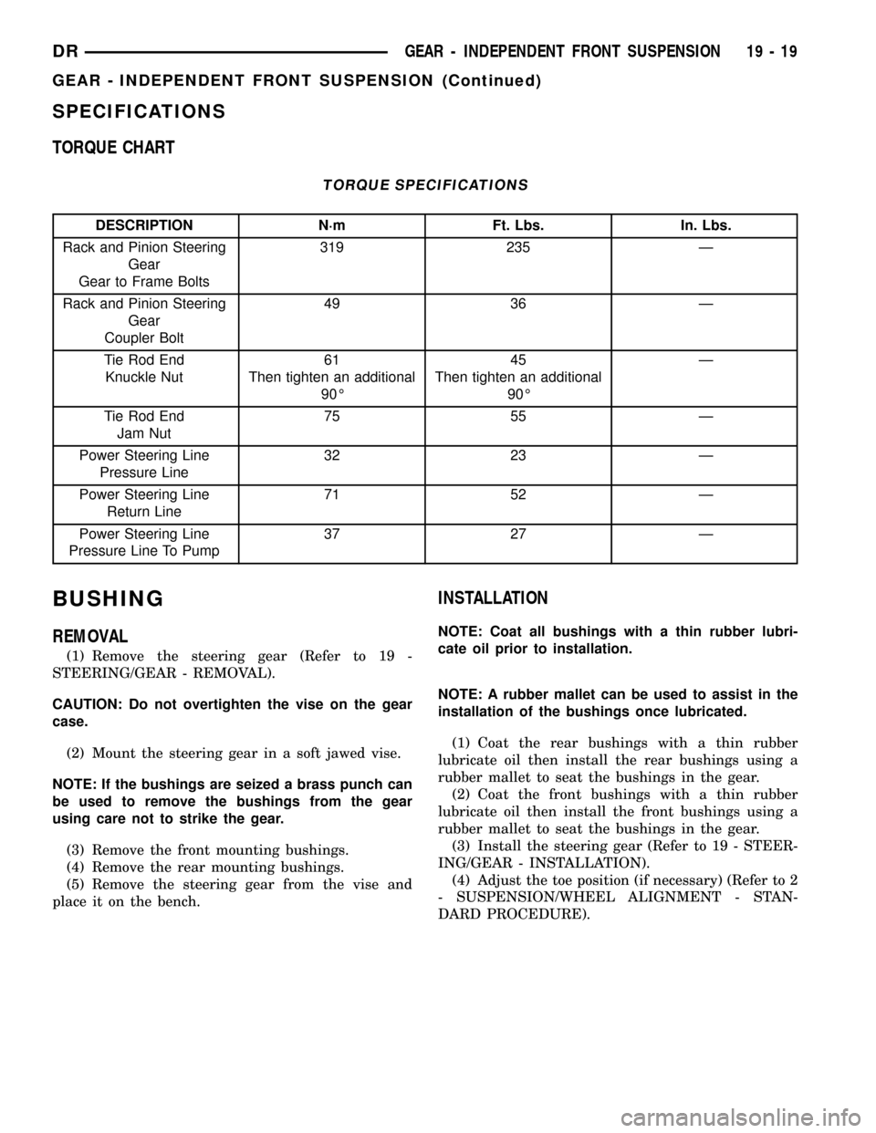
TORQUE CHART
TORQUE SPECIFICATIONS
DESCRIPTION N´m Ft. Lbs. In. Lbs.
Rack and Pinion Steering
Gear
Gear to Frame Bolts319 235 Ð
Rack and Pinion Steering
Gear
Coupler Bolt49 36 Ð
Tie Rod End
Knuckle Nut61
Then tighten an additional
90É45
Then tighten an additional
90ÉÐ
Tie Rod End
Jam Nut75 55 Ð
Power Steering Line
Pressure Line32 23 Ð
Power Steering Line
Return Line71 52 Ð
Power Steering Line
Pressure Line To Pump37 27 Ð
BUSHING
REMOVAL
(1) Remove the steering gear (Refer to 19 -
STEERING/GEAR - REMOVAL).
CAUTION: Do not overtighten the vise on the gear
case.
(2) Mount the steering gear in a soft jawed vise.
NOTE: If the bushings are seized a brass punch can
be used to remove the bushings from the gear
using care not to strike the gear.
(3) Remove the front mounting bushings.
(4) Remove the rear mounting bushings.
(5) Remove the steering gear from the vise and
place it on the bench.
INSTALLATION
NOTE: Coat all bushings with a thin rubber lubri-
cate oil prior to installation.
NOTE: A rubber mallet can be used to assist in the
installation of the bushings once lubricated.
(1) Coat the rear bushings with a thin rubber
lubricate oil then install the rear bushings using a
rubber mallet to seat the bushings in the gear.
(2) Coat the front bushings with a thin rubber
lubricate oil then install the front bushings using a
rubber mallet to seat the bushings in the gear.
(3) Install the steering gear (Refer to 19 - STEER-
ING/GEAR - INSTALLATION).
(4) Adjust the toe position (if necessary) (Refer to 2
- SUSPENSION/WHEEL ALIGNMENT - STAN-
DARD PROCEDURE).
DRGEAR - INDEPENDENT FRONT SUSPENSION 19 - 19
GEAR - INDEPENDENT FRONT SUSPENSION (Continued)
Page 1676 of 2627

(4) Disconnect and cap the fluid hoses from steer-
ing gear (Refer to 19 - STEERING/PUMP/HOSES -
REMOVAL).
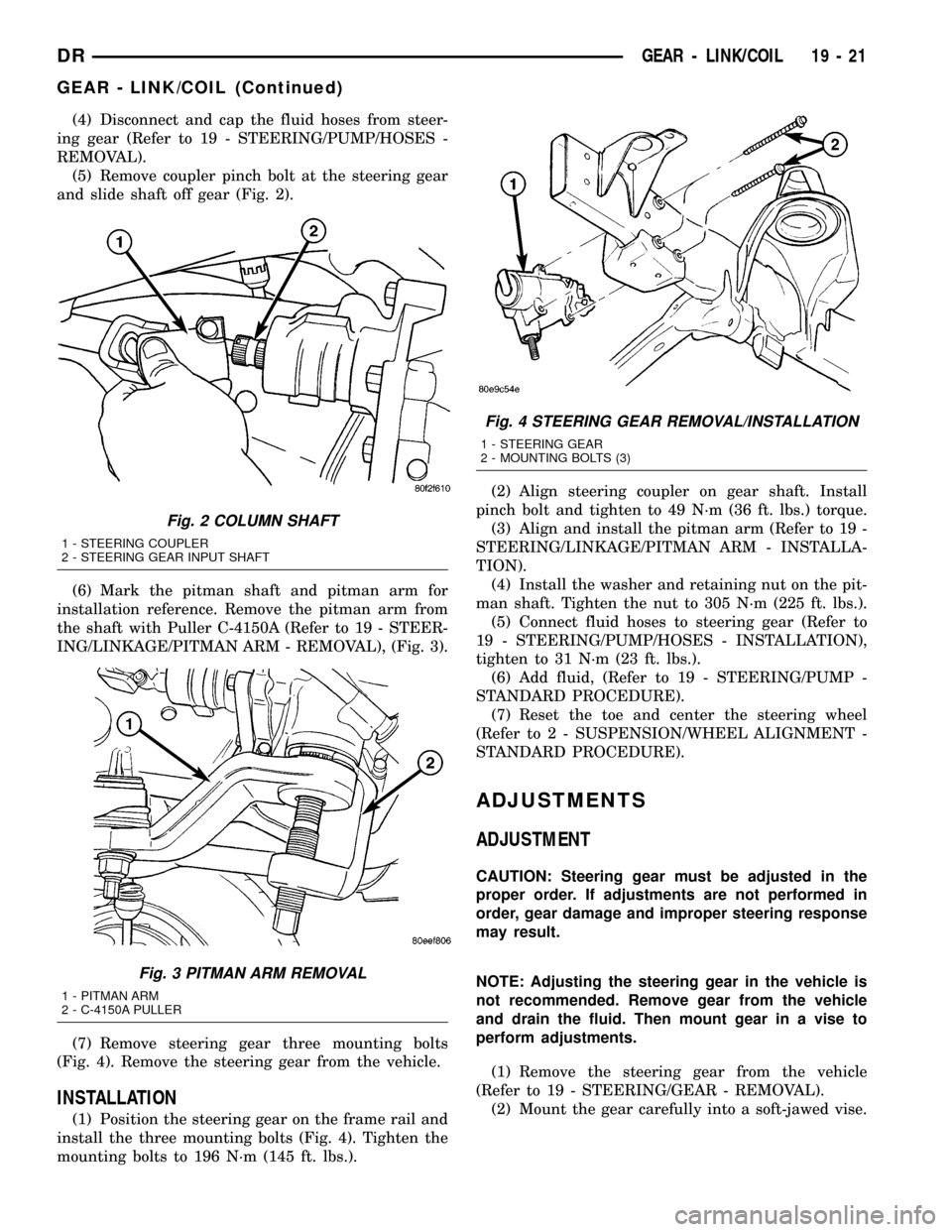
(5) Remove coupler pinch bolt at the steering gear
and slide shaft off gear (Fig. 2).
(6) Mark the pitman shaft and pitman arm for
installation reference. Remove the pitman arm from
the shaft with Puller C-4150A (Refer to 19 - STEER-
ING/LINKAGE/PITMAN ARM - REMOVAL), (Fig. 3).
(7) Remove steering gear three mounting bolts
(Fig. 4). Remove the steering gear from the vehicle.
INSTALLATION
(1) Position the steering gear on the frame rail and
install the three mounting bolts (Fig. 4). Tighten the
mounting bolts to 196 N´m (145 ft. lbs.).(2) Align steering coupler on gear shaft. Install
pinch bolt and tighten to 49 N´m (36 ft. lbs.) torque.
(3) Align and install the pitman arm (Refer to 19 -
STEERING/LINKAGE/PITMAN ARM - INSTALLA-
TION).
(4) Install the washer and retaining nut on the pit-
man shaft. Tighten the nut to 305 N´m (225 ft. lbs.).
(5) Connect fluid hoses to steering gear (Refer to
19 - STEERING/PUMP/HOSES - INSTALLATION),
tighten to 31 N´m (23 ft. lbs.).
(6) Add fluid, (Refer to 19 - STEERING/PUMP -
STANDARD PROCEDURE).
(7) Reset the toe and center the steering wheel
(Refer to 2 - SUSPENSION/WHEEL ALIGNMENT -
STANDARD PROCEDURE).
ADJUSTMENTS
ADJUSTMENT
CAUTION: Steering gear must be adjusted in the
proper order. If adjustments are not performed in
order, gear damage and improper steering response
may result.
NOTE: Adjusting the steering gear in the vehicle is
not recommended. Remove gear from the vehicle
and drain the fluid. Then mount gear in a vise to
perform adjustments.
(1) Remove the steering gear from the vehicle
(Refer to 19 - STEERING/GEAR - REMOVAL).
(2) Mount the gear carefully into a soft-jawed vise.
Fig. 2 COLUMN SHAFT
1 - STEERING COUPLER
2 - STEERING GEAR INPUT SHAFT
Fig. 3 PITMAN ARM REMOVAL
1 - PITMAN ARM
2 - C-4150A PULLER
Fig. 4 STEERING GEAR REMOVAL/INSTALLATION
1 - STEERING GEAR
2 - MOUNTING BOLTS (3)
DRGEAR - LINK/COIL 19 - 21
GEAR - LINK/COIL (Continued)
Page 1687 of 2627

LINKAGE - INDEPENDENT FRONT SUSPENSION
TABLE OF CONTENTS
page page
LINKAGE - INDEPENDENT FRONT
SUSPENSION
DIAGNOSIS AND TESTING - OUTER TIE ROD
END ................................32TIE ROD END
REMOVAL - OUTER TIE ROD END..........32
INSTALLATION - OUTER TIE ROD END......33
LINKAGE - INDEPENDENT
FRONT SUSPENSION
DIAGNOSIS AND TESTING - OUTER TIE ROD
END
NOTE: If the outer tie rod end is equipped with a
lubrication fitting, grease the joint then road test
the vehicle before performing test.
(1) Raise the front of the vehicle. Place safety floor
stands under both lower control arms as far outboard
as possible. Lower the vehicle to allow the stands to
support some or all of the vehicle weight.
(2) Remove the front tires.
(3) Mount a dial indicator solidly to the vehicle
steering knuckle and then zero the dial indicator.
(4) Position indicator plunger on the topside of the
outer tie rod end.
NOTE: The dial indicator plunger must be perpen-
dicular to the machined surface of the outer tie rod
end.
(5) Position a pry bar in order to pry downwards
on the outer tie rod end.
(6) If the travel exceeds 0.5 mm (0.020 in.), replace
the outer tie rod end (Refer to 19 - STEERING/
LINKAGE/TIE ROD END - REMOVAL).
(7) If the outer tie rod end is within specs reinstall
the front tires (Refer to 22 - TIRES/WHEELS/
WHEELS - STANDARD PROCEDURE).
TIE ROD END
REMOVAL - OUTER TIE ROD END
NOTE: Do not twist the boot anytime during
removal or installation.
(1) Loosen the jam nut.
(2) Remove the outer tie rod end nut from the ball
stud.
(3) Separate the tie rod ball stud from the knuckle
with Remover 8677 (Fig. 1).
(4) Unthread the outer tie rod end from the inner
tie rod.
Fig. 1 TIE ROD SEPARATION
1 - TIE ROD END
2 - SPECIAL TOOL 8677
19 - 32 LINKAGE - INDEPENDENT FRONT SUSPENSIONDR
Page 1688 of 2627

INSTALLATION - OUTER TIE ROD END
NOTE: Do not twist the boot at anytime during
removal or installation.
(1) Thread the outer tie rod end onto the inner tie
rod, to it's original position (Fig. 2).
(2) Install the outer tie rod end into the steering
knuckle (Fig. 2).
(3) Tighten the ball stud nut on the ball stud to 61
N´m (45 ft. lbs.) then an additional 90É.
(4) Set wheel toe pattern, (Refer to 2 - SUSPEN-
SION/WHEEL ALIGNMENT - STANDARD PROCE-
DURE).
(5) Tighten jam nut to 75 N´m (55 ft. lbs.) (Fig. 2).
Fig. 2 TIE ROD END
1 - JAM NUT
2 - TIE ROD - INNER
3 - TIE ROD END - OUTER
DRLINKAGE - INDEPENDENT FRONT SUSPENSION 19 - 33
TIE ROD END (Continued)
Page 1689 of 2627

LINKAGE - LINK/COIL
TABLE OF CONTENTS
page page
LINKAGE - LINK/COIL
DESCRIPTION.........................34
STANDARD PROCEDURE - LUBRICATION....34
SPECIFICATIONS
TORQUE CHART......................35
SPECIAL TOOLS
STEERING LINKAGE...................35
DAMPER
REMOVAL.............................36
INSTALLATION.........................36
DRAG LINK
REMOVAL.............................36INSTALLATION.........................36
PITMAN ARM
REMOVAL.............................36
INSTALLATION.........................37
TIE ROD END
REMOVAL.............................37
INSTALLATION.........................37
TRACK BAR
REMOVAL.............................38
INSTALLATION.........................38
LINKAGE - LINK/COIL
DESCRIPTION
The steering linkage is comprised of a tie rod end, tie
rod, drag link, steering damper and pitman arm (Fig. 1).
CAUTION: If any steering components are replaced
or serviced an alignment must be performed.
NOTE: To avoid damaging ball stud seals, use
Puller C-3894±A or an appropriate puller to remove
tie rod ends (Fig. 2).
STANDARD PROCEDURE - LUBRICATION
Periodic lubrication of the steering system compo-
nents is required. Refer to Lubrication And Mainte-
nance for the recommended maintenance schedule.
The following components must be lubricated:
²Tie rod
²Tie rod end
²Drag link
Fig. 1 LINK/COIL FRONT SUSPENSION
1 - STABILIZER BAR
2 - PITMAN ARM
3 - STEERING GEAR
4 - STABILIZER LINK
5 - TIE ROD ENDS
6 - LOWER SUSPENSION ARMS
7 - DRAG LINK
8 - TRACK BAR
9 - DAMPER
10 - UPPER SUSPENSION ARM
Fig. 2 Ball Stud Puller
1 - CLAMP
2 - ADJUSTMENT SLEEVE
3 - PULLER TOOL C-3894±A
4 - SEAL
5 - TIE-ROD END
19 - 34 LINKAGE - LINK/COILDR
Page 1691 of 2627

DAMPER
REMOVAL
(1) Remove the steering damper mounting nuts
and bolts.
(2) Slide the damper from the isolation bushing.
(3) Remove the damper.
INSTALLATION
(1) Install the steering damper on the axle and iso-
lation bushing. Tighten nut to 95 N´m (75 ft. lbs.).
(2) Install the steering damper on the tie rod.
Tighten nut to 81 N´m (60 ft. lbs.).
DRAG LINK
REMOVAL
(1) Remove the draglink nut from the pitman arm
side.
(2)
Remove the drag link nut from the knuckle side.
(3) Remove the drag link from the right knuckle
and pitman arm with Puller C-3894A (Fig. 3).
INSTALLATION
(1) Install the drag link to the pitman arm. Install
the nut and tighten to 88 N´m (65 ft. lbs.).
(2) Install the drag link to the right steering
knuckle. Install the nut and tighten to 108 N´m (80
ft. lbs.).
(3) Install tie rod to the left steering knuckle and
drag link. Install the nuts and tighten to 108 N´m
(80 ft. lbs.).
(4) Remove the supports and lower the vehicle to
the surface. Center steering wheel and adjust toe,
(Refer to 2 - SUSPENSION/WHEEL ALIGNMENT -
STANDARD PROCEDURE).
(5) After adjustment tighten tie rod adjustment
sleeve clamp bolts to 61 N´m (45 ft. lbs.).
NOTE: Position the clamp on the sleeve so retain-
ing bolt is located on the bottom side of the sleeve.
PITMAN ARM
REMOVAL
(1) Remove the drag link from the right knuckle
and pitman arm with Puller C-4150A (Fig. 4).
Fig. 3 DRAGLINK REMOVAL
1 - PITMAN ARM
2 - DRAGLINK
3 - C -3894-A PULLERFig. 4 PITMAN ARM REMOVAL
1 - PITMAN ARM
2 - C-4150A PULLER
19 - 36 LINKAGE - LINK/COILDR
Page 1692 of 2627

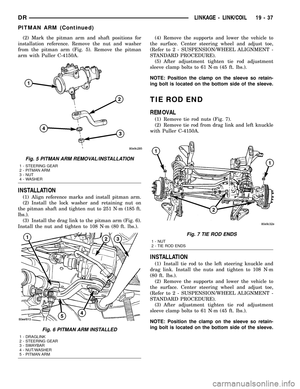
(2) Mark the pitman arm and shaft positions for
installation reference. Remove the nut and washer
from the pitman arm (Fig. 5). Remove the pitman
arm with Puller C-4150A.
INSTALLATION
(1) Align reference marks and install pitman arm.
(2) Install the lock washer and retaining nut on
the pitman shaft and tighten nut to 251 N´m (185 ft.
lbs.).
(3) Install the drag link to the pitman arm (Fig. 6).
Install the nut and tighten to 108 N´m (80 ft. lbs.).(4) Remove the supports and lower the vehicle to
the surface. Center steering wheel and adjust toe,
(Refer to 2 - SUSPENSION/WHEEL ALIGNMENT -
STANDARD PROCEDURE).
(5) After adjustment tighten tie rod adjustment
sleeve clamp bolts to 61 N´m (45 ft. lbs.).
NOTE: Position the clamp on the sleeve so retain-
ing bolt is located on the bottom side of the sleeve.
TIE ROD END
REMOVAL
(1) Remove tie rod nuts (Fig. 7).
(2) Remove tie rod from drag link and left knuckle
with Puller C-4150A.
INSTALLATION
(1) Install tie rod to the left steering knuckle and
drag link. Install the nuts and tighten to 108 N´m
(80 ft. lbs.).
(2) Remove the supports and lower the vehicle to
the surface. Center steering wheel and adjust toe,
(Refer to 2 - SUSPENSION/WHEEL ALIGNMENT -
STANDARD PROCEDURE).
(3) After adjustment tighten tie rod adjustment
sleeve clamp bolts to 61 N´m (45 ft. lbs.).
NOTE: Position the clamp on the sleeve so retain-
ing bolt is located on the bottom side of the sleeve.
Fig. 5 PITMAN ARM REMOVAL/INSTALLATION
1 - STEERING GEAR
2 - PITMAN ARM
3 - NUT
4 - WASHER
Fig. 6 PITMAN ARM INSTALLED
1 - DRAGLINK
2 - STEERING GEAR
3 - SWAYBAR
4 - NUT/WASHER
5 - PITMAN ARM
Fig. 7 TIE ROD ENDS
1 - NUT
2 - TIE ROD ENDS
DRLINKAGE - LINK/COIL 19 - 37
PITMAN ARM (Continued)
Page 1742 of 2627

INSTALLATION
NOTE: If a new transmission is being installed, use
all components supplied with the new transmission.
For example, if a new shift tower is supplied, do not
re-use the original shift tower.
(1) Clean transmission front housing mounting
surface.
(2) Apply light coat of Mopar high temperature
bearing grease or equivalent to contact surfaces (Fig.
126) of following components:
²release fork ball stud.
²release bearing slide surface.
²input shaft splines.
²release bearing bore.
²propeller shaft slip yoke.
(3) Support and secure transmission to jack.
(4) Raise and align transmission input shaft with
clutch disc, then slide transmission into place.
(5) Verify front housing is fully seated. Install
transmission bolts without washers and tighten bolts
into the engine to 41 N´m (30 ft. lbs.). Tighten the
bolts with washers into the transmission to 68 N´m
(50 ft. lbs.) (Fig. 127).(6) Install rear crossmember and tighten nuts to
102 N´m (75 ft. lbs.).
(7) Install transmission rear mounting bolts and
tighten to 68 N´m (50 ft. lbs.).
(8) Install front dust shield tighten bolt to 4.5 N´m
(40 in. lbs.). If cover was removed, install onto the
transmission and engine(Refer to 9 - ENGINE/EN-
GINE BLOCK/STRUCTURAL COVER - INSTALLA-
TION).
(9) Install structural dust cover and tighten the
bolts to 54 N´m (40 ft. lbs.).
(10) Install starter motor.
(11) Install suspension crossmember and tighten
nuts to 102 N´m (75 ft. lbs.).
(12) Connect transmission harnesses to clips on
case and connect switches.
(13) Install slave cylinder and tighten cylinder
nuts to 23 N´m (200 in. lbs.).
(14) Install transfer case and transfer case linkage
if equipped.
(15) Remove transmission jack.
(16) Install propeller shaft/shafts with reference
marks aligned.
(17) Install exhaust on the exhaust manifolds.
(18) Fill transmission with lubricant. Correct fill
level is to bottom edge of fill plug hole.
Fig. 126 LUBRICATION POINTS
1 - RELEASE FORK
2 - FORK BALL STUD
3 - BEARING SLIDE SURFACE
4 - SPLINE
5 - RELEASE BEAING
Fig. 127 TRANSMISSION
1 - BOLT WITHOUT WASHER
2 - BOLT WITH WASHER
DRMANUAL TRANSMISSION - NV3500 21 - 39
MANUAL TRANSMISSION - NV3500 (Continued)