1998 DODGE RAM 1500 Suspension
[x] Cancel search: SuspensionPage 1547 of 2627
INSTALLATION
(1) Align the holes in the bumpers to the trailer
hitch pins and install the bumper.
(2) Install the support bracket to the hitch bolts,
loosely.
(3) Install the front upper edge to the trailer hitch
bolts and tighten to 54 N´m (40 ft. lbs.).
(4) Install the license plate reinforcement to hitch
bolts and tighten to 54 N´m (40 ft. lbs.).
(5) Tighten the left bumper bracket bolts to 54
N´m (40 ft. lbs.).
(6) Tighten the right bumper bracket bolts to 54
N´m (40 ft. lbs.).
(7) Connect the trailer light connector electrical
connection, if equipped.
(8) Connect the license plate light electrical con-
nectors.
(9) Install the license plate.
FRAME
WARNING
SAFETY PRECAUTIONS AND WARNINGS
WARNING: USE EYE PROTECTION WHEN GRIND-
ING OR WELDING METAL, SERIOUS EYE INJURY
CAN RESULT.
²BEFORE PROCEEDING WITH FRAME REPAIR
INVOLVING GRINDING OR WELDING, VERIFY THAT
VEHICLE FUEL SYSTEM IS NOT LEAKING OR IN
CONTACT WITH REPAIR AREA, PERSONAL INJURY
CAN RESULT.
²DO NOT ALLOW OPEN FLAME OR HEAT AND
METAL SPATTER FROM ARC WELDING, TO CON-
TACT PLASTIC BODY PANELS. FIRE OR EXPLO-
SION CAN RESULT.
²WHEN WELDED FRAME COMPONENTS ARE
REPLACED, ENSURE COMPLETE PENETRATION
WELD IS ACHIEVED DURING INSTALLATION. IF
NOT, DANGEROUS OPERATING CONDITIONS CAN
RESULT.
²STAND CLEAR OF CABLES OR CHAINS ON
PULLING EQUIPMENT DURING FRAME STRAIGHT-
ENING OPERATIONS, PERSONAL INJURY CAN
RESULT.
²DO NOT VENTURE UNDER A HOISTED VEHI-
CLE THAT IS NOT SUPPORTED ON SAFETY
STANDS, PERSONAL INJURY CAN RESULT.
CAUTION: 1500 series Dodge Ram Trucks (2002 and
later) are not designed for snow plow equipment.The front collision repair tips must not be installed
on any truck equipped with a snow plow, or even
intended to be equipped with a snow plow.
CAUTION: Do not reuse damaged fasteners, quality
of repair would be suspect. Failure to use only pro-
duction fasteners or fasteners of equivalent hard-
ness can result in loosening or failure. Do not drill
any holes in the frame that are not specifically out-
lined in this or other, DaimlerChrysler procedure as
frame rail failure can result. When using heat to
straighten frame components do not exceed 566ÉC
(1050ÉF), metal fatigue can result.
STANDARD PROCEDURE
STANDARD PROCEDURE - LIGHT DUTY FRONT
FRAME RAIL TIP REPLACEMENT
CAUTION: This procedure is designed to replace
the front frame rail tips that have been damaged in
the crush initiator zones. Prior to any cutting, the
vehicle must be mounted on the appropriate frame
repair equipment (ªframe rackº), checked with three
dimensional measuring equipment, and the neces-
sary pull corrections made. If damage remains in
the frame beyond the area covered by this service
part after the pull, the frame must be replaced in its
entirety.
NOTE: Procedures for 4X2 and 4X4 are common
except as noted in this procedure.
(1) Before proceding with this repair procedure
review the required service warnings and precau-
tions. (Refer to 13 - FRAME & BUMPERS/FRAME -
WARNING)
(2) Disconnect and isolate the battery negative
cable.
(3) Remove the front wheelhouse splash shield.
(Refer to 23 - BODY/EXTERIOR/FRONT WHEEL-
HOUSE SPLASH SHIELD - REMOVAL)
(4) Remove the bolts and position aside the wire
harness and grounds, if required.
(5) Remove the front bumper. (Refer to 13 -
FRAME & BUMPERS/BUMPERS/FRONT BUMPER
- REMOVAL)
(6) Loosen and lower the stabilizer bar mount and
bar. (Refer to 2 - SUSPENSION/FRONT/STABI-
LIZER BAR - REMOVAL)
13 - 4 FRAMES & BUMPERSDR
REAR BUMPER (Continued)
Page 1548 of 2627
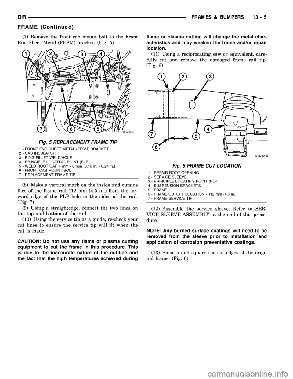
(7) Remove the front cab mount bolt to the Front
End Sheet Metal (FESM) bracket. (Fig. 5)
(8) Make a vertical mark on the inside and outside
face of the frame rail 112 mm (4.5 in.) from the for-
ward edge of the PLP hole in the sides of the rail.
(Fig. 7)
(9) Using a straightedge, connect the two lines on
the top and bottom of the rail.
(10) Using the service tip as a guide, re-check your
cut lines to ensure the service tip will fit when the
cut is made.
CAUTION: Do not use any flame or plasma cutting
equipment to cut the frame in this procedure. This
is due to the inaccurate nature of the cut-line and
the fact that the high temperatures achieved duringflame or plasma cutting will change the metal char-
acteristics and may weaken the frame and/or repair
location.
(11) Using a reciprocating saw or equivalent, care-
fully cut and remove the damaged frame rail tip.
(Fig. 6)
(12) Assemble the service sleeve. Refer to SER-
VICE SLEEVE ASSEMBLY at the end of this proce-
dure.
NOTE: Any burned surface coatings will need to be
removed from the sleeve prior to installation and
application of corrosion preventative coatings.
(13) Smooth and square the cut edges of the origi-
nal frame. (Fig. 6)
Fig. 5 REPLACEMENT FRAME TIP
1 - FRONT END SHEET METAL (FESM) BRACKET
2 - CAB INSULATOR
3 - RING-FILLET WELD/HOLE
4 - PRINCIPLE LOCATING POINT (PLP)
5 - WELD ROOT GAP 4 mm-6mm(0.16 in. - 0.24 in.)
6 - FRONT CAB MOUNT BOLT
7 - REPLACEMENT FRAME TIP
Fig. 6 FRAME CUT LOCATION
1 - REPAIR ROOT OPENING
2 - SERVICE SLEEVE
3 - PRINCIPLE LOCATING POINT (PLP)
4 - SUSPENSION BRACKETS
5 - FRAME
6 - FRAME CUTOFF LOCATION - 112 mm (4.5 in.)
7 - FRAME SERVICE TIP
DRFRAMES & BUMPERS 13 - 5
FRAME (Continued)
Page 1558 of 2627
(26) Install the lower shock absorber bolts. (Refer
to 2 - SUSPENSION/REAR/SHOCK - INSTALLA-
TION)
(27) Install the trailer hitch. (Refer to 13 - FRAME
& BUMPERS/FRAME/TRAILER HITCH - INSTAL-
LATION)(28) Install the cargo box. (Refer to 23 - BODY/EX-
TERIOR/CARGO BOX - INSTALLATION)
(29) Reconnect the battery ground.
SPECIFICATIONS
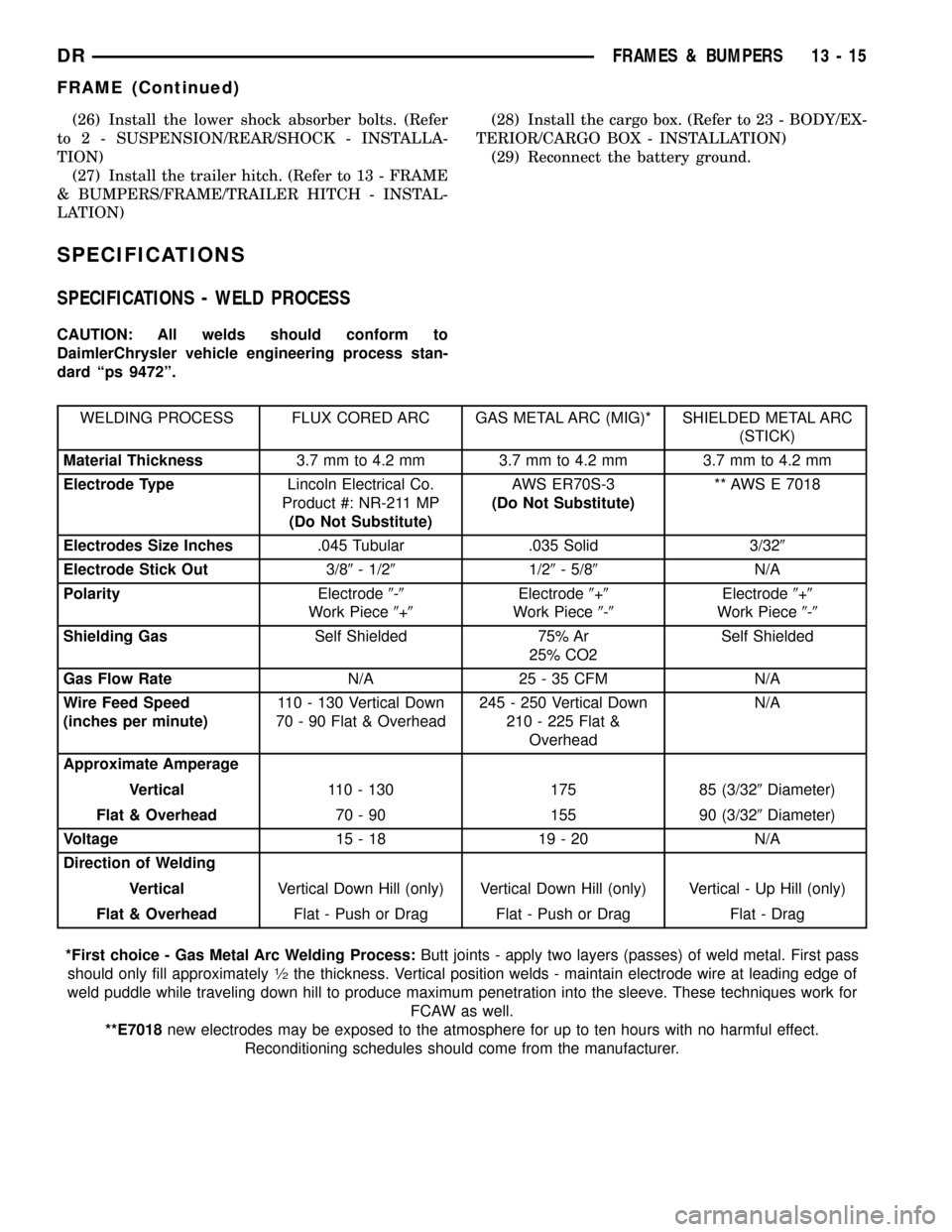
SPECIFICATIONS - WELD PROCESS
CAUTION: All welds should conform to
DaimlerChrysler vehicle engineering process stan-
dard ªps 9472º.
WELDING PROCESS FLUX CORED ARC GAS METAL ARC (MIG)* SHIELDED METAL ARC
(STICK)
Material Thickness3.7 mm to 4.2 mm 3.7 mm to 4.2 mm 3.7 mm to 4.2 mm
Electrode TypeLincoln Electrical Co.
Product #: NR-211 MP
(Do Not Substitute)AWS ER70S-3
(Do Not Substitute)** AWS E 7018
Electrodes Size Inches.045 Tubular .035 Solid 3/329
Electrode Stick Out3/89- 1/291/29- 5/89N/A
PolarityElectrode9-9
Work Piece9+9Electrode9+9
Work Piece9-9Electrode9+9
Work Piece9-9
Shielding GasSelf Shielded 75% Ar
25% CO2Self Shielded
Gas Flow RateN/A 25 - 35 CFM N/A
Wire Feed Speed
(inches per minute)110 - 130 Vertical Down
70 - 90 Flat & Overhead245 - 250 Vertical Down
210 - 225 Flat &
OverheadN/A
Approximate Amperage
Vertical110 - 130 175 85 (3/329Diameter)
Flat & Overhead70 - 90 155 90 (3/329Diameter)
Voltage15-18 19-20 N/A
Direction of Welding
VerticalVertical Down Hill (only) Vertical Down Hill (only) Vertical - Up Hill (only)
Flat & OverheadFlat - Push or Drag Flat - Push or Drag Flat - Drag
*First choice - Gas Metal Arc Welding Process:Butt joints - apply two layers (passes) of weld metal. First pass
should only fill approximately
1¤2the thickness. Vertical position welds - maintain electrode wire at leading edge of
weld puddle while traveling down hill to produce maximum penetration into the sleeve. These techniques work for
FCAW as well.
**E7018new electrodes may be exposed to the atmosphere for up to ten hours with no harmful effect.
Reconditioning schedules should come from the manufacturer.
DRFRAMES & BUMPERS 13 - 15
FRAME (Continued)
Page 1656 of 2627
STEERING
TABLE OF CONTENTS
page page
STEERING
DESCRIPTION..........................1
OPERATION............................1
DIAGNOSIS AND TESTING
DIAGNOSIS AND TESTING - POWER
STEERING SYSTEM....................2
DIAGNOSIS AND TESTING - POWER
STEERING FLOW AND PRESSURE........4
SPECIAL TOOLS
STEERING...........................5COLUMN...............................6
GEAR - INDEPENDENT FRONT SUSPENSION..17
GEAR - LINK/COIL.......................20
LINKAGE - INDEPENDENT FRONT
SUSPENSION...........................32
LINKAGE - LINK/COIL....................34
PUMP.................................39
STEERING
DESCRIPTION
CAUTION: MOPARTATF+4 is to be used in the
power steering system. No other power steering or
automatic transmission fluid is to be used in the
system. Damage may result to the power steering
pump and system if any other fluid is used, and do
not overfill.
Power steering systems consist of:
²Steering column
²Rack and pinion steering gear
²Belt driven hydraulic steering pump
²Pump pressure and return hoses
²Oil Cooler
OPERATION
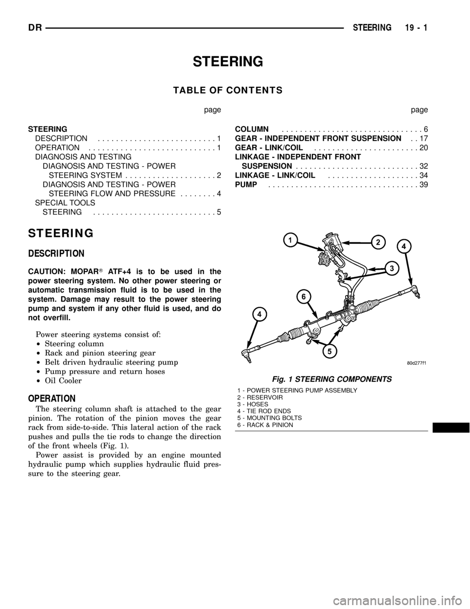
The steering column shaft is attached to the gear
pinion. The rotation of the pinion moves the gear
rack from side-to-side. This lateral action of the rack
pushes and pulls the tie rods to change the direction
of the front wheels (Fig. 1).
Power assist is provided by an engine mounted
hydraulic pump which supplies hydraulic fluid pres-
sure to the steering gear.
Fig. 1 STEERING COMPONENTS
1 - POWER STEERING PUMP ASSEMBLY
2 - RESERVOIR
3 - HOSES
4 - TIE ROD ENDS
5 - MOUNTING BOLTS
6 - RACK & PINION
DRSTEERING 19 - 1
Page 1657 of 2627
DIAGNOSIS AND TESTING
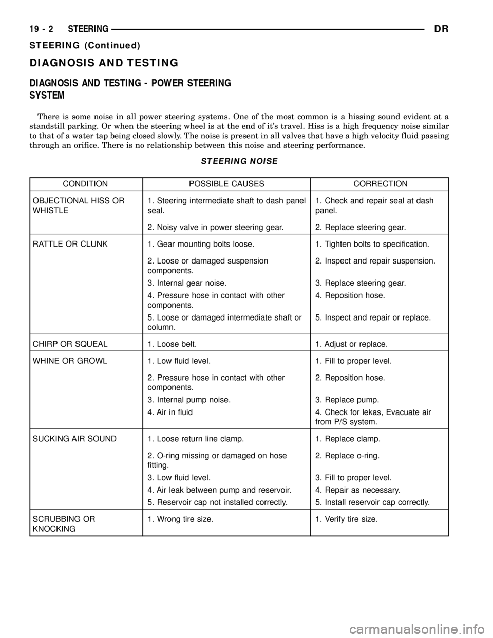
DIAGNOSIS AND TESTING - POWER STEERING
SYSTEM
There is some noise in all power steering systems. One of the most common is a hissing sound evident at a
standstill parking. Or when the steering wheel is at the end of it's travel. Hiss is a high frequency noise similar
to that of a water tap being closed slowly. The noise is present in all valves that have a high velocity fluid passing
through an orifice. There is no relationship between this noise and steering performance.
STEERING NOISE
CONDITION POSSIBLE CAUSES CORRECTION
OBJECTIONAL HISS OR
WHISTLE1. Steering intermediate shaft to dash panel
seal.1. Check and repair seal at dash
panel.
2. Noisy valve in power steering gear. 2. Replace steering gear.
RATTLE OR CLUNK 1. Gear mounting bolts loose. 1. Tighten bolts to specification.
2. Loose or damaged suspension
components.2. Inspect and repair suspension.
3. Internal gear noise. 3. Replace steering gear.
4. Pressure hose in contact with other
components.4. Reposition hose.
5. Loose or damaged intermediate shaft or
column.5. Inspect and repair or replace.
CHIRP OR SQUEAL 1. Loose belt. 1. Adjust or replace.
WHINE OR GROWL 1. Low fluid level. 1. Fill to proper level.
2. Pressure hose in contact with other
components.2. Reposition hose.
3. Internal pump noise. 3. Replace pump.
4. Air in fluid 4. Check for lekas, Evacuate air
from P/S system.
SUCKING AIR SOUND 1. Loose return line clamp. 1. Replace clamp.
2. O-ring missing or damaged on hose
fitting.2. Replace o-ring.
3. Low fluid level. 3. Fill to proper level.
4. Air leak between pump and reservoir. 4. Repair as necessary.
5. Reservoir cap not installed correctly. 5. Install reservoir cap correctly.
SCRUBBING OR
KNOCKING1. Wrong tire size. 1. Verify tire size.
19 - 2 STEERINGDR
STEERING (Continued)
Page 1658 of 2627
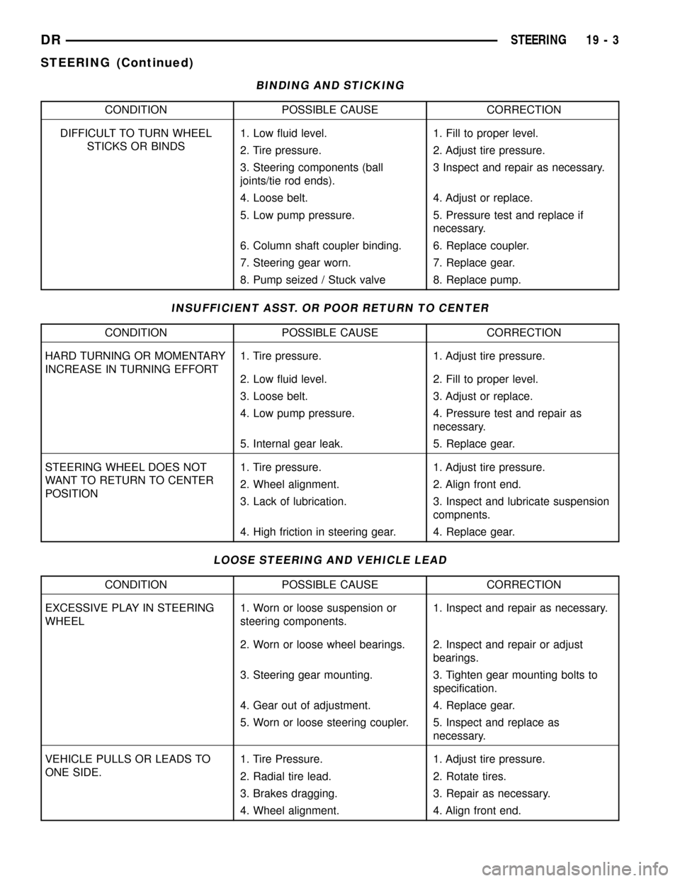
BINDING AND STICKING
CONDITION POSSIBLE CAUSE CORRECTION
DIFFICULT TO TURN WHEEL
STICKS OR BINDS1. Low fluid level. 1. Fill to proper level.
2. Tire pressure. 2. Adjust tire pressure.
3. Steering components (ball
joints/tie rod ends).3 Inspect and repair as necessary.
4. Loose belt. 4. Adjust or replace.
5. Low pump pressure. 5. Pressure test and replace if
necessary.
6. Column shaft coupler binding. 6. Replace coupler.
7. Steering gear worn. 7. Replace gear.
8. Pump seized / Stuck valve 8. Replace pump.
INSUFFICIENT ASST. OR POOR RETURN TO CENTER
CONDITION POSSIBLE CAUSE CORRECTION
HARD TURNING OR MOMENTARY
INCREASE IN TURNING EFFORT1. Tire pressure. 1. Adjust tire pressure.
2. Low fluid level. 2. Fill to proper level.
3. Loose belt. 3. Adjust or replace.
4. Low pump pressure. 4. Pressure test and repair as
necessary.
5. Internal gear leak. 5. Replace gear.
STEERING WHEEL DOES NOT
WANT TO RETURN TO CENTER
POSITION1. Tire pressure. 1. Adjust tire pressure.
2. Wheel alignment. 2. Align front end.
3. Lack of lubrication. 3. Inspect and lubricate suspension
compnents.
4. High friction in steering gear. 4. Replace gear.
LOOSE STEERING AND VEHICLE LEAD
CONDITION POSSIBLE CAUSE CORRECTION
EXCESSIVE PLAY IN STEERING
WHEEL1. Worn or loose suspension or
steering components.1. Inspect and repair as necessary.
2. Worn or loose wheel bearings. 2. Inspect and repair or adjust
bearings.
3. Steering gear mounting. 3. Tighten gear mounting bolts to
specification.
4. Gear out of adjustment. 4. Replace gear.
5. Worn or loose steering coupler. 5. Inspect and replace as
necessary.
VEHICLE PULLS OR LEADS TO
ONE SIDE.1. Tire Pressure. 1. Adjust tire pressure.
2. Radial tire lead. 2. Rotate tires.
3. Brakes dragging. 3. Repair as necessary.
4. Wheel alignment. 4. Align front end.
DRSTEERING 19 - 3
STEERING (Continued)
Page 1672 of 2627
GEAR - INDEPENDENT FRONT SUSPENSION
TABLE OF CONTENTS
page page
GEAR - INDEPENDENT FRONT SUSPENSION
DESCRIPTION.........................17
REMOVAL.............................17
INSTALLATION.........................18
SPECIFICATIONS
TORQUE CHART......................19BUSHING
REMOVAL.............................19
INSTALLATION.........................19
GEAR - INDEPENDENT FRONT
SUSPENSION
DESCRIPTION
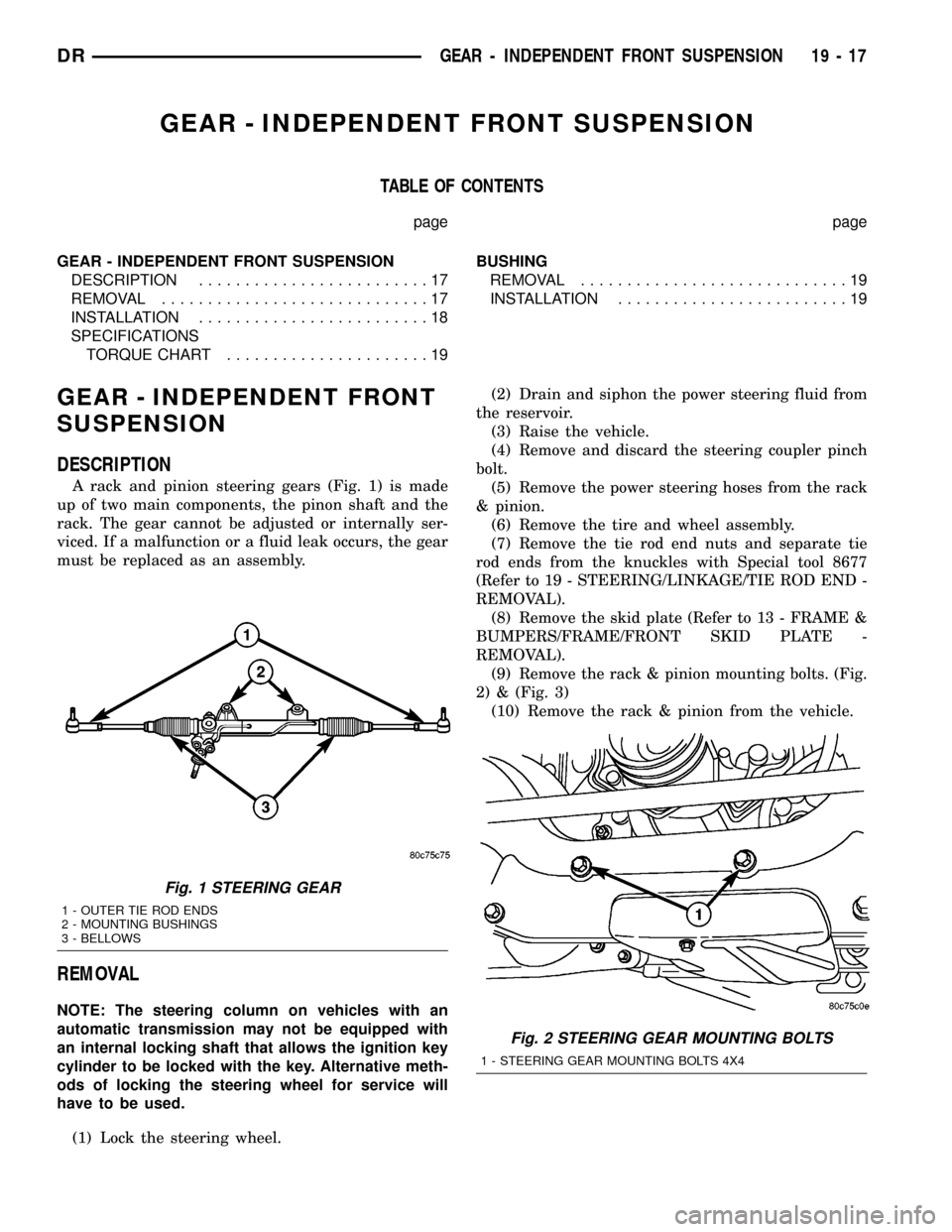
A rack and pinion steering gears (Fig. 1) is made
up of two main components, the pinon shaft and the
rack. The gear cannot be adjusted or internally ser-
viced. If a malfunction or a fluid leak occurs, the gear
must be replaced as an assembly.
REMOVAL
NOTE: The steering column on vehicles with an
automatic transmission may not be equipped with
an internal locking shaft that allows the ignition key
cylinder to be locked with the key. Alternative meth-
ods of locking the steering wheel for service will
have to be used.
(1) Lock the steering wheel.(2) Drain and siphon the power steering fluid from
the reservoir.
(3) Raise the vehicle.
(4) Remove and discard the steering coupler pinch
bolt.
(5) Remove the power steering hoses from the rack
& pinion.
(6) Remove the tire and wheel assembly.
(7) Remove the tie rod end nuts and separate tie
rod ends from the knuckles with Special tool 8677
(Refer to 19 - STEERING/LINKAGE/TIE ROD END -
REMOVAL).
(8) Remove the skid plate (Refer to 13 - FRAME &
BUMPERS/FRAME/FRONT SKID PLATE -
REMOVAL).
(9) Remove the rack & pinion mounting bolts. (Fig.
2) & (Fig. 3)
(10) Remove the rack & pinion from the vehicle.
Fig. 1 STEERING GEAR
1 - OUTER TIE ROD ENDS
2 - MOUNTING BUSHINGS
3 - BELLOWS
Fig. 2 STEERING GEAR MOUNTING BOLTS
1 - STEERING GEAR MOUNTING BOLTS 4X4
DRGEAR - INDEPENDENT FRONT SUSPENSION 19 - 17
Page 1673 of 2627
INSTALLATION
NOTE: Before installing gear inspect bushings and
replace if worn or damaged.
NOTE: In the frame there is two holes for the
mounting of the steering gear one is slotted and
one is round, When tightening the gear to specifi-
cations make sure to tighten the mounting bolt with
the hole first to avoided movement of the steering
gear.
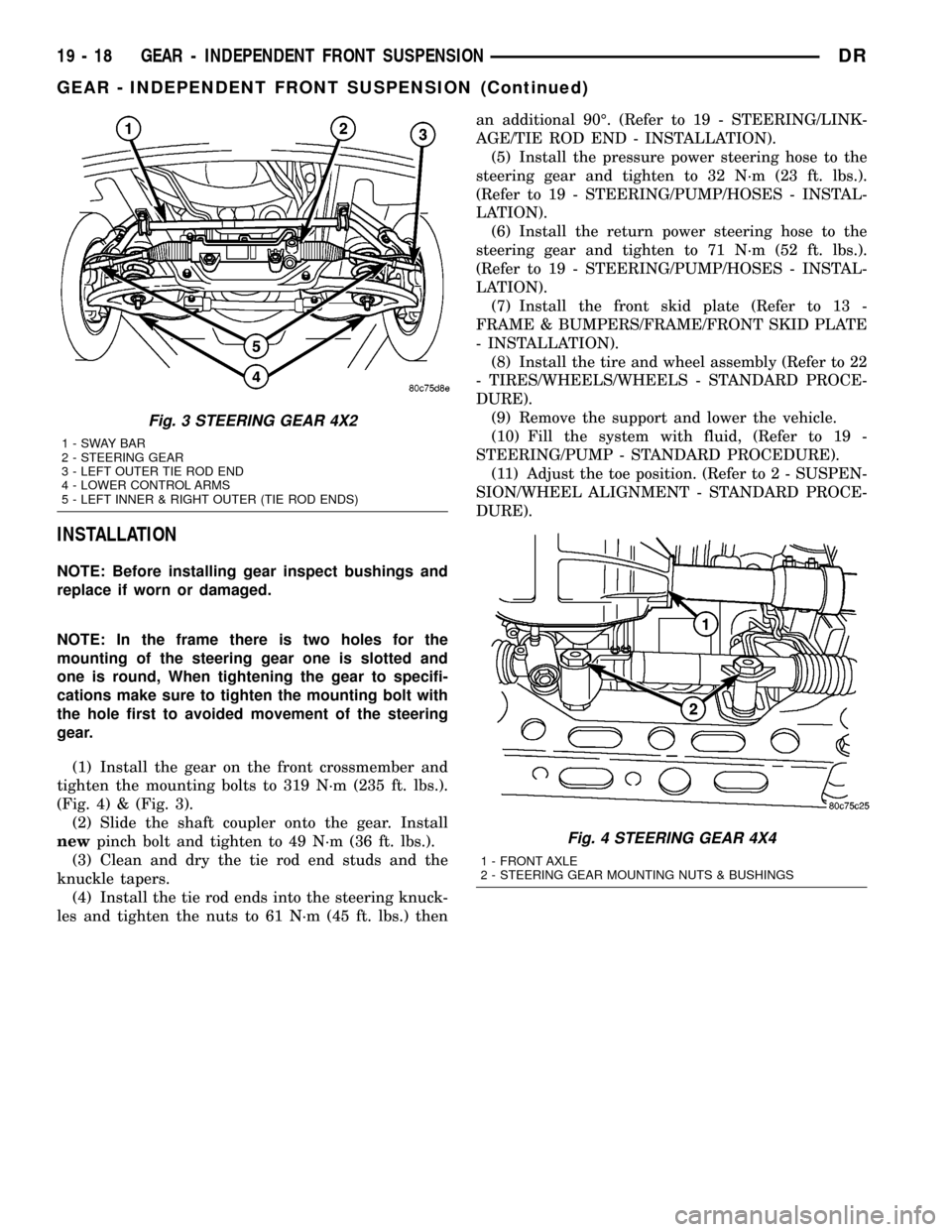
(1) Install the gear on the front crossmember and
tighten the mounting bolts to 319 N´m (235 ft. lbs.).
(Fig. 4) & (Fig. 3).
(2) Slide the shaft coupler onto the gear. Install
newpinch bolt and tighten to 49 N´m (36 ft. lbs.).
(3) Clean and dry the tie rod end studs and the
knuckle tapers.
(4) Install the tie rod ends into the steering knuck-
les and tighten the nuts to 61 N´m (45 ft. lbs.) thenan additional 90É. (Refer to 19 - STEERING/LINK-
AGE/TIE ROD END - INSTALLATION).
(5) Install the pressure power steering hose to the
steering gear and tighten to 32 N´m (23 ft. lbs.).
(Refer to 19 - STEERING/PUMP/HOSES - INSTAL-
LATION).
(6) Install the return power steering hose to the
steering gear and tighten to 71 N´m (52 ft. lbs.).
(Refer to 19 - STEERING/PUMP/HOSES - INSTAL-
LATION).
(7) Install the front skid plate (Refer to 13 -
FRAME & BUMPERS/FRAME/FRONT SKID PLATE
- INSTALLATION).
(8) Install the tire and wheel assembly (Refer to 22
- TIRES/WHEELS/WHEELS - STANDARD PROCE-
DURE).
(9) Remove the support and lower the vehicle.
(10) Fill the system with fluid, (Refer to 19 -
STEERING/PUMP - STANDARD PROCEDURE).
(11) Adjust the toe position. (Refer to 2 - SUSPEN-
SION/WHEEL ALIGNMENT - STANDARD PROCE-
DURE).
Fig. 3 STEERING GEAR 4X2
1-SWAYBAR
2 - STEERING GEAR
3 - LEFT OUTER TIE ROD END
4 - LOWER CONTROL ARMS
5 - LEFT INNER & RIGHT OUTER (TIE ROD ENDS)
Fig. 4 STEERING GEAR 4X4
1 - FRONT AXLE
2 - STEERING GEAR MOUNTING NUTS & BUSHINGS
19 - 18 GEAR - INDEPENDENT FRONT SUSPENSIONDR
GEAR - INDEPENDENT FRONT SUSPENSION (Continued)