1998 DODGE RAM 1500 Starting
[x] Cancel search: StartingPage 1318 of 2627
to one gasket surface. Be certain the material sur-
rounds each mounting hole. Excess material can eas-
ily be wiped off. Components should be torqued in
place within 15 minutes. The use of a locating dowel
is recommended during assembly to prevent smear-
ing material off the location.
MopartEngine RTV GEN II or ATF RTV gasket
material should be applied in a continuous bead
approximately 3 mm (0.120 in.) in diameter. All
mounting holes must be circled. For corner sealing, a
3.17 or 6.35 mm (1/8 or 1/4 in.) drop is placed in the
center of the gasket contact area. Uncured sealant
may be removed with a shop towel. Components
should be torqued in place while the sealant is still
wet to the touch (within 10 minutes). The usage of a
locating dowel is recommended during assembly to
prevent smearing material off the location.
MopartGasket Sealant in an aerosol can should be
applied using a thin, even coat sprayed completely
over both surfaces to be joined, and both sides of a
gasket. Then proceed with assembly. Material in a
can w/applicator can be brushed on evenly over the
sealing surfaces. Material in an aerosol can should be
used on engines with multi-layer steel gaskets.
REMOVAL
NOTE: This procedure applies to both the 4X2 and
4X4 vehicles, steps that apply to the 4X4 vehicle
only, are identified.
(1) Disconnect the battery negative and positive
cables.
(2) Remove the battery and the battery tray.
(3) Raise vehicle on hoist.
(4) Remove exhaust crossover pipe from exhaust
manifolds.
(5)4X4 vehiclesDisconnect axle vent tube from
left side engine mount.
(6) Remove the through bolt retaining nut and bolt
from both the left and right side engine mounts.
(7)4X4 vehiclesRemove locknut from left and
right side engine mount brackets.
(8) Disconnect two ground straps from the lower
left hand side and one ground strap from the lower
right hand side of the engine.
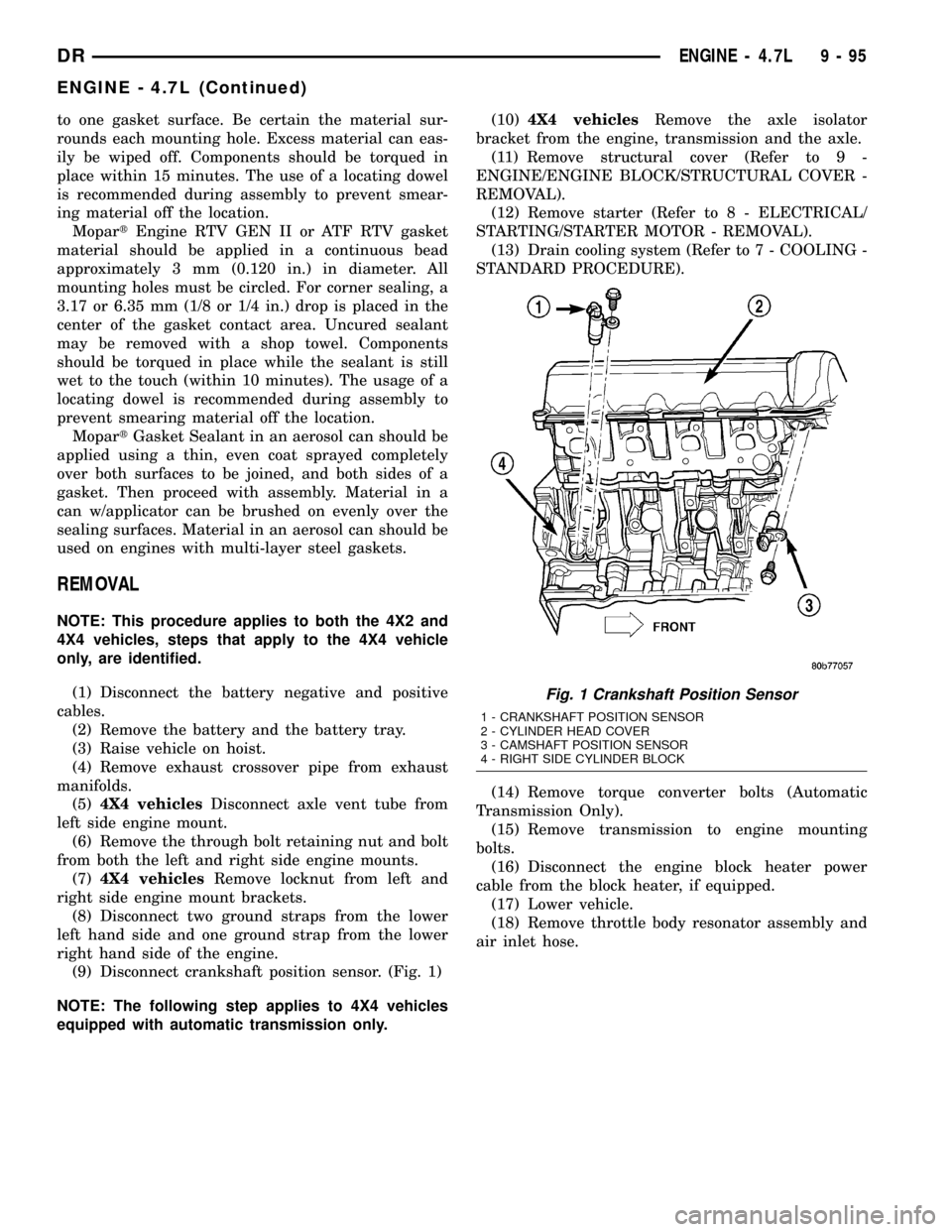
(9) Disconnect crankshaft position sensor. (Fig. 1)
NOTE: The following step applies to 4X4 vehicles
equipped with automatic transmission only.(10)4X4 vehiclesRemove the axle isolator
bracket from the engine, transmission and the axle.
(11) Remove structural cover (Refer to 9 -
ENGINE/ENGINE BLOCK/STRUCTURAL COVER -
REMOVAL).
(12) Remove starter (Refer to 8 - ELECTRICAL/
STARTING/STARTER MOTOR - REMOVAL).
(13) Drain cooling system (Refer to 7 - COOLING -
STANDARD PROCEDURE).
(14) Remove torque converter bolts (Automatic
Transmission Only).
(15) Remove transmission to engine mounting
bolts.
(16) Disconnect the engine block heater power
cable from the block heater, if equipped.
(17) Lower vehicle.
(18) Remove throttle body resonator assembly and
air inlet hose.
Fig. 1 Crankshaft Position Sensor
1 - CRANKSHAFT POSITION SENSOR
2 - CYLINDER HEAD COVER
3 - CAMSHAFT POSITION SENSOR
4 - RIGHT SIDE CYLINDER BLOCK
DRENGINE - 4.7L 9 - 95
ENGINE - 4.7L (Continued)
Page 1321 of 2627
Position both the left and right side engine mount
brackets and install the through bolts and nuts.
Tighten nuts to4X2 vehicles95 N´m (70 ft. lbs.).
4X4 vehicles102 N´m (75 ft. lbs.).
(2)4X4 vehiclesInstall locknuts onto the engine
mount brackets. Tighten locknuts to 41 N´m (30 ft.
lbs.).
(3) Remove jack from under the transmission.
(4) Remove Engine Lifting Fixture Special Tool
8347 (Fig. 4).
(5) Remove Special Tools 8400 Lifting Studs.
(6) Position generator wiring behind the oil dip-
stick tube, then install the oil dipstick tube upper
mounting bolt.
(7) Connect both left and right side body ground
straps.
(8) Install power steering pump.
(9) Connect fuel supply line quick connect fitting
(Refer to 14 - FUEL SYSTEM/FUEL DELIVERY/
QUICK CONNECT FITTING - STANDARD PROCE-
DURE).
(10) Connect the vacuum lines at the throttle body
and intake manifold.
(11) Connect engine harness at the following
points (Fig. 3):
²Intake Air Temperature (IAT) Sensor
²Idle Air Control (IAC) Motor
²Fuel Injectors
²Throttle Position (TPS) Switch
²Engine Oil Pressure Switch
²Engine Coolant Temperature (ECT) Sensor
²Manifold Absolute Pressure (MAP) Sensor
²Camshaft Position (CMP) Sensor
²Coil Over Plugs
(12) Position and install heater hoses and tubes
onto intake manifold.
(13) Install the heater hoses onto the heater core
and the engine front cover.
(14) Install generator (Refer to 8 - ELECTRICAL/
CHARGING/GENERATOR - INSTALLATION).
(15) Install A/C condenser (Refer to 24 - HEATING
& AIR CONDITIONING/PLUMBING/A/C CON-
DENSER - INSTALLATION), radiator (Refer to 7 -
COOLING/ENGINE/RADIATOR - INSTALLATION)
and transmission oil cooler.
(16) Connect radiator upper and lower hoses.
(17) Connect the transmission oil cooler lines to
the radiator.
(18) Install accessory drive belt (Refer to 7 -
COOLING/ACCESSORY DRIVE/DRIVE BELTS -INSTALLATION), fan assembly and shroud (Refer to
7 - COOLING/ENGINE/FAN DRIVE VISCOUS
CLUTCH - INSTALLATION).
(19) Install A/C compressor (Refer to 24 - HEAT-
ING & AIR CONDITIONING/PLUMBING/A/C COM-
PRESSOR - INSTALLATION).
(20) Install both breathers. Connect tube to both
crankcase breathers (Fig. 2).
(21) Connect throttle and speed control cables.
(22) Install throttle body resonator assembly and
air inlet hose. Tighten clamps 4 N´m (35 in. lbs.).
(23) Raise vehicle.
(24) Install transmission to engine mounting bolts.
Tighten the bolts to 41 N´m (30 ft. lbs.).
(25) Install torque converter bolts (Automatic
Transmission Only).
(26) Connect crankshaft position sensor (Fig. 1).
(27)4X4 vehiclesPosition and install the axle
isolator bracket onto the axle, transmission and
engine block. Tighten bolts to specification (Refer to 9
- ENGINE - SPECIFICATIONS).
(28) Install starter (Refer to 8 - ELECTRICAL/
STARTING/STARTER MOTOR - INSTALLATION).
CAUTION: The structural cover requires a specific
torque sequence. Failure to follow this sequence
may cause severe damage to the cover.
(29) Install structural cover (Refer to 9 - ENGINE/
ENGINE BLOCK/STRUCTURAL COVER - INSTAL-
LATION).
(30) Install exhaust crossover pipe.
(31) Install engine block heater power cable, If
equipped.
(32)4X4 vehiclesConnect axle vent tube to left
side engine mount.
(33) Lower vehicle.
(34) Check and fill engine oil.
(35) Recharge the A/C system (Refer to 24 - HEAT-
ING & AIR CONDITIONING/PLUMBING/REFRIG-
ERANT - STANDARD PROCEDURE).
(36) Refill the engine cooling system (Refer to 7 -
COOLING - STANDARD PROCEDURE).
(37) Install the battery tray and battery.
(38) Connect the battery positive and negative
cables.
(39) Start the engine and check for leaks.
9 - 98 ENGINE - 4.7LDR
ENGINE - 4.7L (Continued)
Page 1339 of 2627

(6) Hold the camshaft with adjustable pliers while
removing the camshaft sprocket bolt and sprocket
(Fig. 26).
(7) Using the pliers, gently allow the camshaft to
rotate 15É clockwise until the camshaft is in the neu-
tral position (no valve load).
(8) Starting at the outside working inward, loosen
the camshaft bearing cap retaining bolts 1/2 turn at
a time. Repeat until all load is off the bearing caps.
CAUTION: DO NOT STAMP OR STRIKE THE CAM-
SHAFT BEARING CAPS. SEVERE DAMAGE WILL
OCCUR TO THE BEARING CAPS.
NOTE: When the camshaft is removed the rocker
arms may slide downward, mark the rocker arms
before removing camshaft.
(9) Remove the camshaft bearing caps and the
camshaft.INSTALLATION
(1) Lubricate camshaft journals with clean engine
oil.
NOTE: Position the left side camshaft so that the
camshaft sprocket dowel is near the 1 o'clock posi-
tion, This will place the camshaft at the neutral
position easing the installation of the camshaft
bearing caps.
(2) Position the camshaft into the cylinder head.
(3) Install the camshaft bearing caps, hand tighten
the retaining bolts.
(4) Working in
1¤2turn increments, tighten the
bearing cap retaining bolts starting with the middle
cap working outward (Fig. 27).
Fig. 26 Camshaft Sprocket and Chain
1 - CAMSHAFT SPROCKET AND CHAIN
2 - ADJUSTABLE PLIERS
3 - CAMSHAFT
Fig. 27 Camshaft Bearing Caps Tightening
Sequence
9 - 116 ENGINE - 4.7LDR
CAMSHAFT(S) - LEFT (Continued)
Page 1343 of 2627
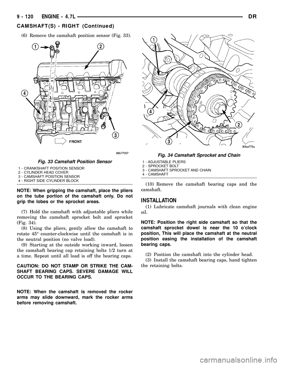
(6) Remove the camshaft position sensor (Fig. 33).
NOTE: When gripping the camshaft, place the pliers
on the tube portion of the camshaft only. Do not
grip the lobes or the sprocket areas.
(7) Hold the camshaft with adjustable pliers while
removing the camshaft sprocket bolt and sprocket
(Fig. 34).
(8) Using the pliers, gently allow the camshaft to
rotate 45É counter-clockwise until the camshaft is in
the neutral position (no valve load).
(9) Starting at the outside working inward, loosen
the camshaft bearing cap retaining bolts 1/2 turn at
a time. Repeat until all load is off the bearing caps.
CAUTION: DO NOT STAMP OR STRIKE THE CAM-
SHAFT BEARING CAPS. SEVERE DAMAGE WILL
OCCUR TO THE BEARING CAPS.
NOTE: When the camshaft is removed the rocker
arms may slide downward, mark the rocker arms
before removing camshaft.(10) Remove the camshaft bearing caps and the
camshaft.
INSTALLATION
(1) Lubricate camshaft journals with clean engine
oil.
NOTE: Position the right side camshaft so that the
camshaft sprocket dowel is near the 10 o'clock
position, This will place the camshaft at the neutral
position easing the installation of the camshaft
bearing caps.
(2) Position the camshaft into the cylinder head.
(3) Install the camshaft bearing caps, hand tighten
the retaining bolts.
Fig. 33 Camshaft Position Sensor
1 - CRANKSHAFT POSITION SENSOR
2 - CYLINDER HEAD COVER
3 - CAMSHAFT POSITION SENSOR
4 - RIGHT SIDE CYLINDER BLOCK
Fig. 34 Camshaft Sprocket and Chain
1 - ADJUSTABLE PLIERS
2 - SPROCKET BOLT
3 - CAMSHAFT SPROCKET AND CHAIN
4 - CAMSHAFT
9 - 120 ENGINE - 4.7LDR
CAMSHAFT(S) - RIGHT (Continued)
Page 1344 of 2627
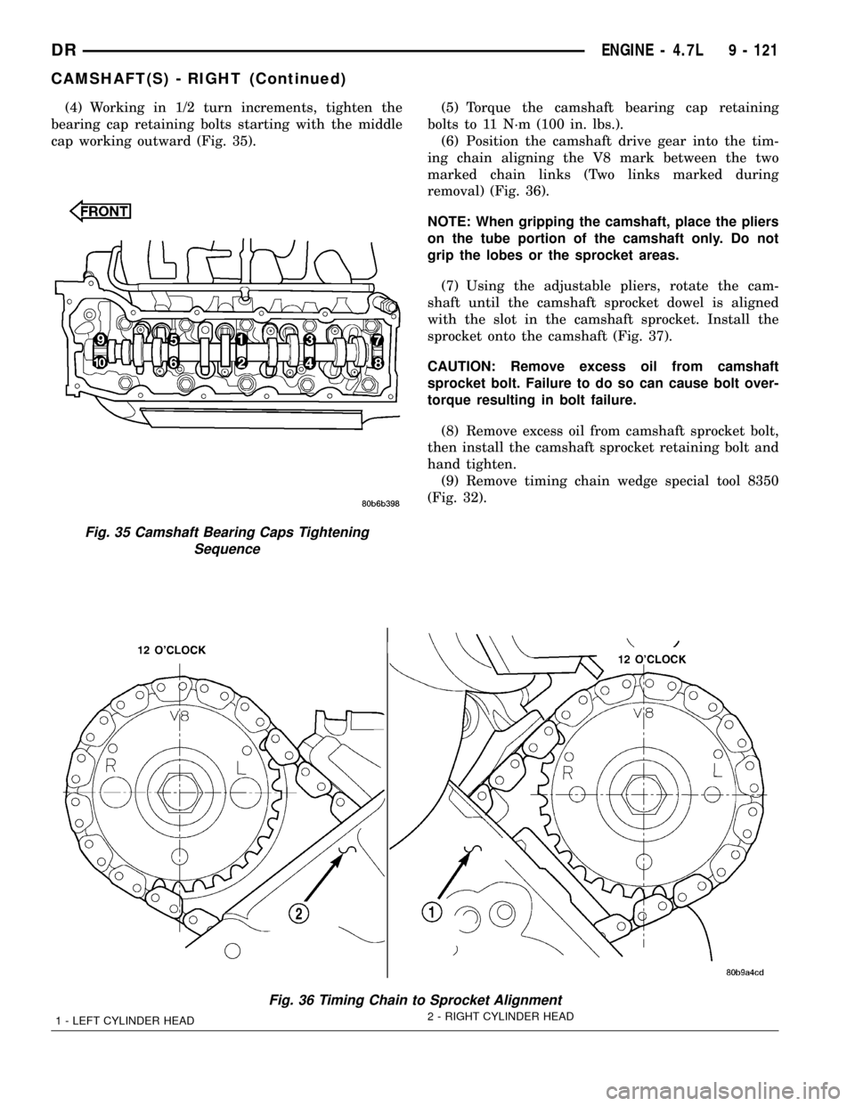
(4) Working in 1/2 turn increments, tighten the
bearing cap retaining bolts starting with the middle
cap working outward (Fig. 35).(5) Torque the camshaft bearing cap retaining
bolts to 11 N´m (100 in. lbs.).
(6) Position the camshaft drive gear into the tim-
ing chain aligning the V8 mark between the two
marked chain links (Two links marked during
removal) (Fig. 36).
NOTE: When gripping the camshaft, place the pliers
on the tube portion of the camshaft only. Do not
grip the lobes or the sprocket areas.
(7) Using the adjustable pliers, rotate the cam-
shaft until the camshaft sprocket dowel is aligned
with the slot in the camshaft sprocket. Install the
sprocket onto the camshaft (Fig. 37).
CAUTION: Remove excess oil from camshaft
sprocket bolt. Failure to do so can cause bolt over-
torque resulting in bolt failure.
(8) Remove excess oil from camshaft sprocket bolt,
then install the camshaft sprocket retaining bolt and
hand tighten.
(9) Remove timing chain wedge special tool 8350
(Fig. 32).
Fig. 36 Timing Chain to Sprocket Alignment
1 - LEFT CYLINDER HEAD2 - RIGHT CYLINDER HEAD
Fig. 35 Camshaft Bearing Caps Tightening
Sequence
DRENGINE - 4.7L 9 - 121
CAMSHAFT(S) - RIGHT (Continued)
Page 1348 of 2627
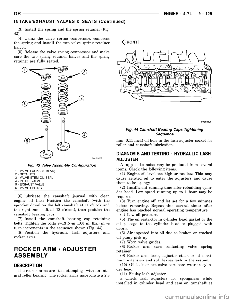
(3) Install the spring and the spring retainer (Fig.
43).
(4) Using the valve spring compressor, compress
the spring and install the two valve spring retainer
halves.
(5) Release the valve spring compressor and make
sure the two spring retainer halves and the spring
retainer are fully seated.
(6) lubricate the camshaft journal with clean
engine oil then Position the camshaft (with the
sprocket dowel on the left camshaft at 11 o'clock and
the right camshaft at 12 o'clock), then position the
camshaft bearing caps.
(7) Install the camshaft bearing cap retaining
bolts. Tighten the bolts 9±13 N´m (100 in. lbs.) in
1¤2
turn increments in the sequence shown (Fig. 44).
(8) Position the hydraulic lash adjusters and
rocker arms.
ROCKER ARM / ADJUSTER
ASSEMBLY
DESCRIPTION
The rocker arms are steel stampings with an inte-
gral roller bearing. The rocker arms incorporate a 2.8mm (0.11 inch) oil hole in the lash adjuster socket for
roller and camshaft lubrication.
DIAGNOSIS AND TESTING - HYDRAULIC LASH
ADJUSTER
A tappet-like noise may be produced from several
items. Check the following items.
(1) Engine oil level too high or too low. This may
cause aerated oil to enter the adjusters and cause
them to be spongy.
(2) Insufficient running time after rebuilding cylin-
der head. Low speed running up to 1 hour may be
required.
(3) Turn engine off and let set for a few minutes
before restarting. Repeat this several times after
engine has reached normal operating temperature.
(4) Low oil pressure.
(5) The oil restrictor in cylinder head gasket or the
oil passage to the cylinder head is plugged with
debris.
(6) Air ingested into oil due to broken or cracked
oil pump pick up.
(7) Worn valve guides.
(8) Rocker arm ears contacting valve spring
retainer.
(9) Rocker arm loose, adjuster stuck or at maxi-
mum extension and still leaves lash in the system.
(10) Oil leak or excessive cam bore wear in cylin-
der head.
(11) Faulty lash adjuster.
a. Check lash adjusters for sponginess while
installed in cylinder head and cam on camshaft atFig. 43 Valve Assembly Configuration
1 - VALVE LOCKS (3±BEAD)
2 - RETAINER
3 - VALVE STEM OIL SEAL
4 - INTAKE VALVE
5 - EXHAUST VALVE
6 - VALVE SPRING
Fig. 44 Camshaft Bearing Caps Tightening
Sequence
DRENGINE - 4.7L 9 - 125
INTAKE/EXHAUST VALVES & SEATS (Continued)
Page 1363 of 2627
tons covered during this operation.Pistons and
connecting rods must be removed from top of cylinder
block. When removing piston and connecting rod
assemblies from the engine, rotate crankshaft so the
each connecting rod is centered in cylinder bore.
CAUTION: DO NOT use a number stamp or a punch
to mark connecting rods or caps, as damage to
connecting rods could occur
NOTE: Connecting rods and bearing caps are not
interchangeable and should be marked before
removing to ensure correct reassembly.
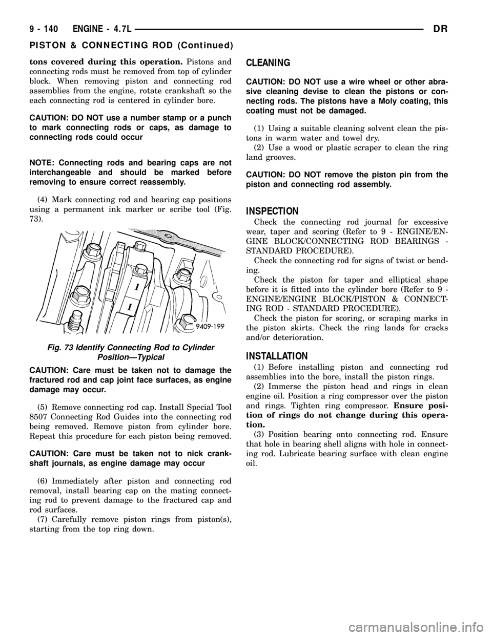
(4) Mark connecting rod and bearing cap positions
using a permanent ink marker or scribe tool (Fig.
73).
CAUTION: Care must be taken not to damage the
fractured rod and cap joint face surfaces, as engine
damage may occur.
(5) Remove connecting rod cap. Install Special Tool
8507 Connecting Rod Guides into the connecting rod
being removed. Remove piston from cylinder bore.
Repeat this procedure for each piston being removed.
CAUTION: Care must be taken not to nick crank-
shaft journals, as engine damage may occur
(6) Immediately after piston and connecting rod
removal, install bearing cap on the mating connect-
ing rod to prevent damage to the fractured cap and
rod surfaces.
(7) Carefully remove piston rings from piston(s),
starting from the top ring down.CLEANING
CAUTION: DO NOT use a wire wheel or other abra-
sive cleaning devise to clean the pistons or con-
necting rods. The pistons have a Moly coating, this
coating must not be damaged.
(1) Using a suitable cleaning solvent clean the pis-
tons in warm water and towel dry.
(2) Use a wood or plastic scraper to clean the ring
land grooves.
CAUTION: DO NOT remove the piston pin from the
piston and connecting rod assembly.
INSPECTION
Check the connecting rod journal for excessive
wear, taper and scoring (Refer to 9 - ENGINE/EN-
GINE BLOCK/CONNECTING ROD BEARINGS -
STANDARD PROCEDURE).
Check the connecting rod for signs of twist or bend-
ing.
Check the piston for taper and elliptical shape
before it is fitted into the cylinder bore (Refer to 9 -
ENGINE/ENGINE BLOCK/PISTON & CONNECT-
ING ROD - STANDARD PROCEDURE).
Check the piston for scoring, or scraping marks in
the piston skirts. Check the ring lands for cracks
and/or deterioration.
INSTALLATION
(1) Before installing piston and connecting rod
assemblies into the bore, install the piston rings.
(2) Immerse the piston head and rings in clean
engine oil. Position a ring compressor over the piston
and rings. Tighten ring compressor.Ensure posi-
tion of rings do not change during this opera-
tion.
(3) Position bearing onto connecting rod. Ensure
that hole in bearing shell aligns with hole in connect-
ing rod. Lubricate bearing surface with clean engine
oil.
Fig. 73 Identify Connecting Rod to Cylinder
PositionÐTypical
9 - 140 ENGINE - 4.7LDR
PISTON & CONNECTING ROD (Continued)
Page 1369 of 2627
CAUTION: The structural cover must be held tightly
against both the engine and the transmission bell
housing during tightening sequence. Failure to do
so may cause damage to the cover.
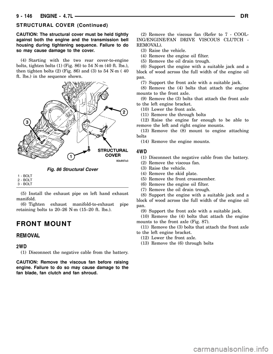
(4) Starting with the two rear cover-to-engine
bolts, tighten bolts (1) (Fig. 86) to 54 N´m (40 ft. lbs.),
then tighten bolts (2) (Fig. 86) and (3) to 54 N´m ( 40
ft. lbs.) in the sequence shown.
(5) Install the exhaust pipe on left hand exhaust
manifold.
(6) Tighten exhaust manifold-to-exhaust pipe
retaining bolts to 20±26 N´m (15±20 ft. lbs.).
FRONT MOUNT
REMOVAL
2WD
(1) Disconnect the negative cable from the battery.
CAUTION: Remove the viscous fan before raising
engine. Failure to do so may cause damage to the
fan blade, fan clutch and fan shroud.(2) Remove the viscous fan (Refer to 7 - COOL-
ING/ENGINE/FAN DRIVE VISCOUS CLUTCH -
REMOVAL).
(3) Raise the vehicle.
(4) Remove the engine oil filter.
(5) Remove the oil drain trough.
(6) Support the engine with a suitable jack and a
block of wood across the full width of the engine oil
pan.
(7) Support the front axle with a suitable jack.
(8) Remove the (4) bolts that attach the engine
mounts to the front axle.
(9) Remove the (3) bolts that attach the front axle
to the left engine bracket.
(10) Lower the front axle.
(11) Remove the through bolts
(12) Raise the engine far enough to be able to
remove the left and right engine mounts.
(13) Remove the (8) mount to engine attaching
bolts
(14) Remove the engine mounts.
4WD
(1) Disconnect the negative cable from the battery.
(2) Remove the viscous fan.
(3) Raise the vehicle.
(4) Remove the skid plate.
(5) Remove the front crossmember.
(6) Remove the engine oil filter.
(7) Remove the oil drain trough.
(8) Support the engine with a suitable jack and a
block of wood across the full width of the engine oil
pan.
(9) Support the front axle with a suitable jack.
(10) Remove the (4) bolts that attach the engine
mounts to the front axle (Fig. 87).
(11) Remove the (3) bolts that attach the front axle
to the left engine bracket.
(12) Lower the front axle.
(13) Remove the (6) through bolts
Fig. 86 Structural Cover
1 - BOLT
2 - BOLT
3 - BOLT
9 - 146 ENGINE - 4.7LDR
STRUCTURAL COVER (Continued)