1998 DODGE RAM 1500 Camshaft removal
[x] Cancel search: Camshaft removalPage 1492 of 2627
(15) Remove the two charge air cooler mounting
bolts.
(16) Remove charge air cooler (and A/C condenser
if equipped) from vehicle.
(17) Remove accessory drive belt (Refer to 7 -
COOLING/ACCESSORY DRIVE/DRIVE BELTS -
REMOVAL).
(18) Remove accessory drive belt tensioner.
(19) Remove the fan support/hub assembly.
(20) Remove crankshaft damper and speed indica-
tor ring (Refer to 9 - ENGINE/ENGINE BLOCK/VI-
BRATION DAMPER - REMOVAL).
(21) Remove the gear cover-to-housing bolts and
gently pry the cover away from the housing, taking
care not to mar the sealing surfaces. Remove dust
seal with cover.
(22) Using Special Tool 7471±B Crankshaft Bar-
ring Tool, rotate the crankshaft to align the timing
marks on the crankshaft and the camshaft gears.
(23) Remove the cylinder head cover (Refer to 9 -
ENGINE/CYLINDER HEAD/CYLINDER HEAD
COVER(S) - REMOVAL).
(24) Remove the rocker arms, cross heads, and
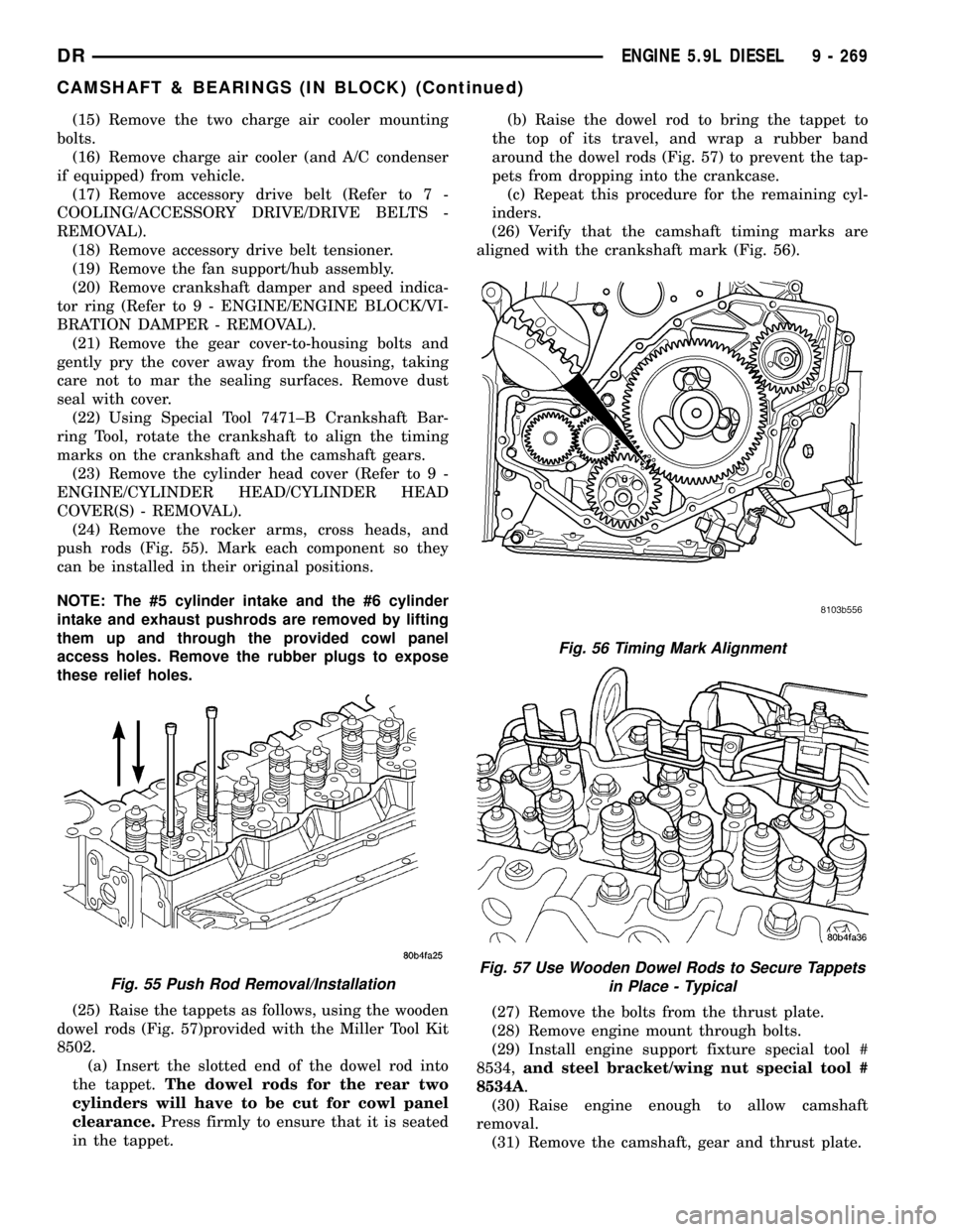
push rods (Fig. 55). Mark each component so they
can be installed in their original positions.
NOTE: The #5 cylinder intake and the #6 cylinder
intake and exhaust pushrods are removed by lifting
them up and through the provided cowl panel
access holes. Remove the rubber plugs to expose
these relief holes.
(25) Raise the tappets as follows, using the wooden
dowel rods (Fig. 57)provided with the Miller Tool Kit
8502.
(a) Insert the slotted end of the dowel rod into
the tappet.The dowel rods for the rear two
cylinders will have to be cut for cowl panel
clearance.Press firmly to ensure that it is seated
in the tappet.(b) Raise the dowel rod to bring the tappet to
the top of its travel, and wrap a rubber band
around the dowel rods (Fig. 57) to prevent the tap-
pets from dropping into the crankcase.
(c) Repeat this procedure for the remaining cyl-
inders.
(26) Verify that the camshaft timing marks are
aligned with the crankshaft mark (Fig. 56).
(27) Remove the bolts from the thrust plate.
(28) Remove engine mount through bolts.
(29) Install engine support fixture special tool #
8534,and steel bracket/wing nut special tool #
8534A.
(30) Raise engine enough to allow camshaft
removal.
(31) Remove the camshaft, gear and thrust plate.
Fig. 55 Push Rod Removal/Installation
Fig. 56 Timing Mark Alignment
Fig. 57 Use Wooden Dowel Rods to Secure Tappets
in Place - Typical
DRENGINE 5.9L DIESEL 9 - 269
CAMSHAFT & BEARINGS (IN BLOCK) (Continued)
Page 1493 of 2627
INSPECTION
Camshaft
(1) Inspect the valve lobes and bearing journals for
cracks, pitting, scoring, or generally excessive wear.
Replace any camshaft that exceeds the allowable lim-
its.
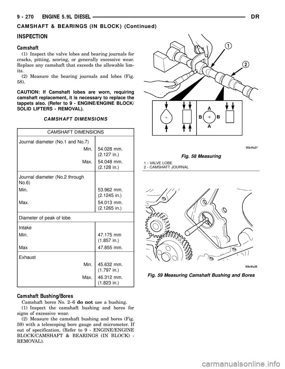
(2) Measure the bearing journals and lobes (Fig.
58).
CAUTION: If Camshaft lobes are worn, requiring
camshaft replacement, it is necessary to replace the
tappets also. (Refer to 9 - ENGINE/ENGINE BLOCK/
SOLID LIFTERS - REMOVAL).
CAMSHAFT DIMENSIONS
CAMSHAFT DIMENSIONS
Journal diameter (No.1 and No.7)
Min. 54.028 mm.
(2.127 in.)
Max. 54.048 mm.
(2.128 in.)
Journal diameter (No.2 through
No.6)
Min. 53.962 mm.
(2.1245 in.)
Max. 54.013 mm.
(2.1265 in.)
Diameter of peak of lobe
Intake
Min. 47.175 mm
(1.857 in.)
Max 47.855 mm.
Exhaust
Min. 45.632 mm.
(1.797 in.)
Max. 46.312 mm.
(1.823 in.)
Camshaft Bushing/Bores
Camshaft bores No. 2±6do notuse a bushing.
(1) Inspect the camshaft bushing and bores for
signs of excessive wear.
(2) Measure the camshaft bushing and bores (Fig.
59) with a telescoping bore gauge and micrometer. If
out of specification, (Refer to 9 - ENGINE/ENGINE
BLOCK/CAMSHAFT & BEARINGS (IN BLOCK) -
REMOVAL).
Fig. 59 Measuring Camshaft Bushing and Bores
Fig. 58 Measuring
1 - VALVE LOBE
2 - CAMSHAFT JOURNAL
9 - 270 ENGINE 5.9L DIESELDR
CAMSHAFT & BEARINGS (IN BLOCK) (Continued)
Page 1494 of 2627
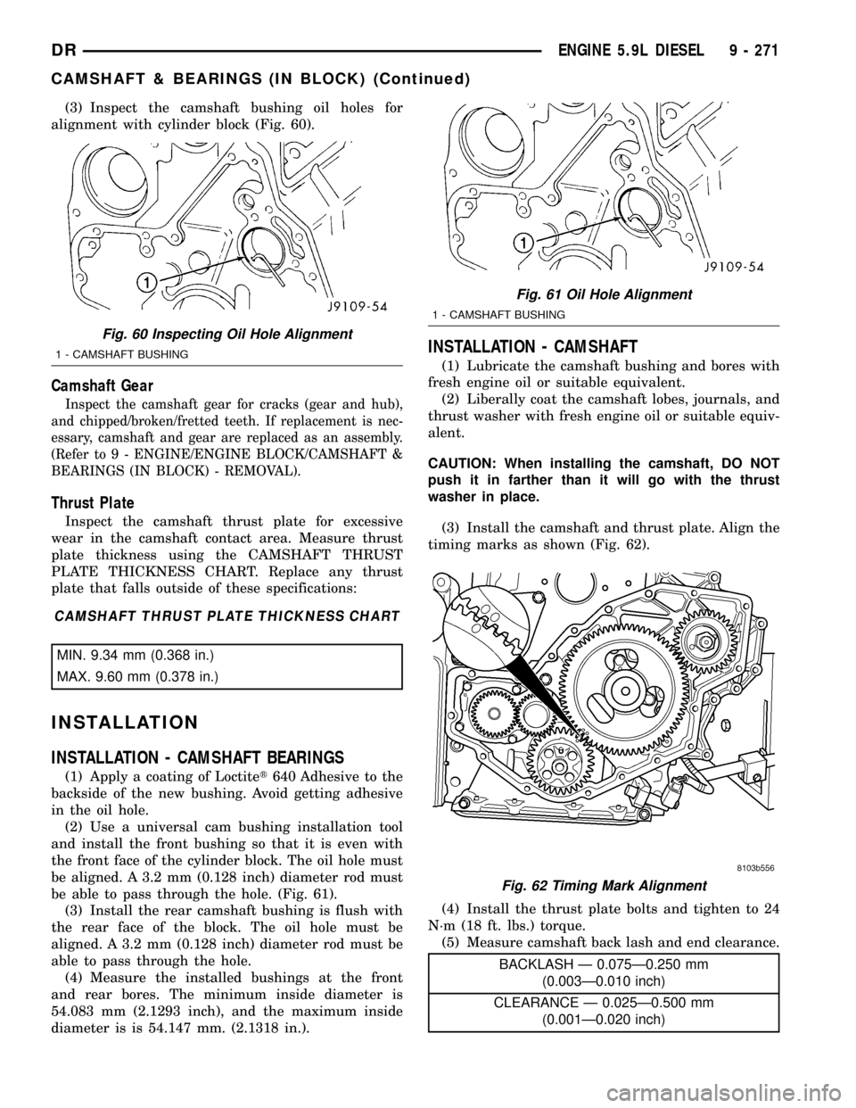
(3) Inspect the camshaft bushing oil holes for
alignment with cylinder block (Fig. 60).
Camshaft Gear
Inspect the camshaft gear for cracks (gear and hub),
and chipped/broken/fretted teeth. If replacement is nec-
essary, camshaft and gear are replaced as an assembly.
(Refer to 9 - ENGINE/ENGINE BLOCK/CAMSHAFT &
BEARINGS (IN BLOCK) - REMOVAL).
Thrust Plate
Inspect the camshaft thrust plate for excessive
wear in the camshaft contact area. Measure thrust
plate thickness using the CAMSHAFT THRUST
PLATE THICKNESS CHART. Replace any thrust
plate that falls outside of these specifications:
CAMSHAFT THRUST PLATE THICKNESS CHART
MIN. 9.34 mm (0.368 in.)
MAX. 9.60 mm (0.378 in.)
INSTALLATION
INSTALLATION - CAMSHAFT BEARINGS
(1) Apply a coating of Loctitet640 Adhesive to the
backside of the new bushing. Avoid getting adhesive
in the oil hole.
(2) Use a universal cam bushing installation tool
and install the front bushing so that it is even with
the front face of the cylinder block. The oil hole must
be aligned. A 3.2 mm (0.128 inch) diameter rod must
be able to pass through the hole. (Fig. 61).
(3) Install the rear camshaft bushing is flush with
the rear face of the block. The oil hole must be
aligned. A 3.2 mm (0.128 inch) diameter rod must be
able to pass through the hole.
(4) Measure the installed bushings at the front
and rear bores. The minimum inside diameter is
54.083 mm (2.1293 inch), and the maximum inside
diameter is is 54.147 mm. (2.1318 in.).
INSTALLATION - CAMSHAFT
(1) Lubricate the camshaft bushing and bores with
fresh engine oil or suitable equivalent.
(2) Liberally coat the camshaft lobes, journals, and
thrust washer with fresh engine oil or suitable equiv-
alent.
CAUTION: When installing the camshaft, DO NOT
push it in farther than it will go with the thrust
washer in place.
(3) Install the camshaft and thrust plate. Align the
timing marks as shown (Fig. 62).
(4) Install the thrust plate bolts and tighten to 24
N´m (18 ft. lbs.) torque.
(5) Measure camshaft back lash and end clearance.
BACKLASH Ð 0.075Ð0.250 mm
(0.003Ð0.010 inch)
CLEARANCE Ð 0.025Ð0.500 mm
(0.001Ð0.020 inch)
Fig. 60 Inspecting Oil Hole Alignment
1 - CAMSHAFT BUSHING
Fig. 61 Oil Hole Alignment
1 - CAMSHAFT BUSHING
Fig. 62 Timing Mark Alignment
DRENGINE 5.9L DIESEL 9 - 271
CAMSHAFT & BEARINGS (IN BLOCK) (Continued)
Page 1502 of 2627
SOLID LIFTERS/TAPPETS
REMOVAL
NOTE: This procedure requires use of Miller Tool
8502 Tappet Replacement Kit.
(1) Remove camshaft (Refer to 9 - ENGINE/EN-
GINE BLOCK/CAMSHAFT & BEARINGS (IN
BLOCK) - REMOVAL).
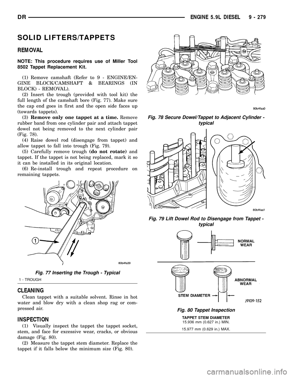
(2) Insert the trough (provided with tool kit) the
full length of the camshaft bore (Fig. 77). Make sure
the cap end goes in first and the open side faces up
(towards tappets).
(3)Remove only one tappet at a time.Remove
rubber band from one cylinder pair and attach tappet
dowel not being removed to the next cylinder pair
(Fig. 78).
(4) Raise dowel rod (disengage from tappet) and
allow tappet to fall into trough (Fig. 79).
(5) Carefully remove trough(do not rotate)and
tappet. If the tappet is not being replaced, mark it so
it can be installed in its original location.
(6) Re-install trough and repeat procedure on
remaining tappets.
CLEANING
Clean tappet with a suitable solvent. Rinse in hot
water and blow dry with a clean shop rag or com-
pressed air.
INSPECTION
(1) Visually inspect the tappet the tappet socket,
stem, and face for excessive wear, cracks, or obvious
damage (Fig. 80).
(2) Measure the tappet stem diameter. Replace the
tappet if it falls below the minimum size (Fig. 80).
Fig. 77 Inserting the Trough - Typical
1 - TROUGH
Fig. 78 Secure Dowel/Tappet to Adjacent Cylinder -
typical
Fig. 79 Lift Dowel Rod to Disengage from Tappet -
typical
Fig. 80 Tappet Inspection
TAPPET STEM DIAMETER
15.936 mm (0.627 in.) MIN.
15.977 mm (0.629 in.) MAX.
DRENGINE 5.9L DIESEL 9 - 279
Page 1504 of 2627
PISTON & CONNECTING ROD
DESCRIPTION
PISTONS
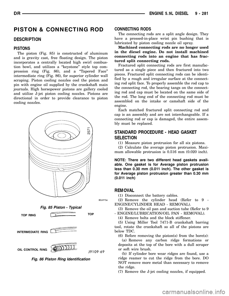
The piston (Fig. 85) is constructed of aluminum
and is gravity cast, free floating design. The piston
incorporates a centrally located high swirl combus-
tion bowl, and utilizes a ªkeystoneº style top com-
pression ring (Fig. 86), and a ªTapered Faceº
intermediate ring (Fig. 86), for superior cylinder wall
scraping. Piston cooling nozzles cool the piston and
pin with engine oil supplied by the crankshaft main
journals. High horsepower pistons are gallery cooled
and utilize J-jet piston cooling nozzles. Pistons are
directional in order to provide clearance to piston
cooling nozzles.
CONNECTING RODS
The connecting rods are a split angle design. They
have a pressed-in-place wrist pin bushing that is
lubricated by piston cooling nozzle oil spray.
Machined connecting rods are no longer used
in the diesel engine. Do not install machined
connecting rods into an engine that has frac-
tured split connecting rods.
Fractured split connecting rods are first manufac-
tured as a single piece and then fractured into two
pieces. Fractured split connecting rods can be identi-
fied by a rough and irregular surface at the connect-
ing rod split face. To properly assemble the rod cap to
the connecting rod, the bearing tangs on the connect-
ing rod and cap must be located on the same side of
the rod. The long end of the connecting rod must be
assembled on the intake or camshaft side of the
engine.
Each matched fractured split connecting rod and
cap is an assembly and are not interchangeable. If a
connecting rod or cap is damaged, the entire assem-
bly must be replaced.
STANDARD PROCEDURE - HEAD GASKET
SELECTION
(1) Measure piston protrusion for all six pistons.
(2) Calculate the average piston protrusion. Maxi-
mum allowable protrusion is 0.516 mm (0.020 inch).
NOTE: There are two different head gaskets avail-
able. One gasket is for Average piston protrusion
less than 0.30 mm (0.011 inch). The other gasket is
for Average piston protrusion greater than 0.30 mm
(0.011 inch)
REMOVAL
(1) Disconnect the battery cables.
(2) Remove the cylinder head (Refer to 9 -
ENGINE/CYLINDER HEAD - REMOVAL).
(3) Remove the oil pan and suction tube (Refer to 9
- ENGINE/LUBRICATION/OIL PAN - REMOVAL).
(4) Remove bolts and the block stiffener.
(5) Using Miller Tool 7471-B crankshaft barring
tool, rotate the crankshaft so all of the pistons are
below TDC.
(6) Before removing the piston(s) from the bore(s):
(a) Remove any carbon ridge formations or
deposits at the top of the bore with a dull scraper
or soft wire brush.
(b) If cylinder bore wear ridges are found, use a
ridge reamer to cut the ridge from the bore. DO
NOT remove more metal than necessary to remove
the ridge.
(7) Remove the J-jet cooling nozzles, if equipped.
Fig. 85 Piston - Typical
Fig. 86 Piston Ring Identification
DRENGINE 5.9L DIESEL 9 - 281
Page 1515 of 2627
OIL
STANDARD PROCEDURE
STANDARD PROCEDURE - ENGINE OIL LEVEL
CAUTION: Do not overfill crankcase with engine oil,
oil foaming and oil pressure loss can result.
To ensure proper lubrication of an engine, the
engine oil must be maintained at an acceptable level.
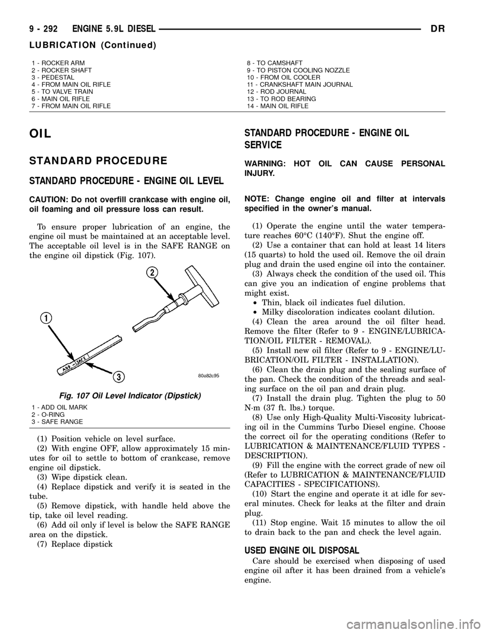
The acceptable oil level is in the SAFE RANGE on
the engine oil dipstick (Fig. 107).
(1) Position vehicle on level surface.
(2) With engine OFF, allow approximately 15 min-
utes for oil to settle to bottom of crankcase, remove
engine oil dipstick.
(3) Wipe dipstick clean.
(4) Replace dipstick and verify it is seated in the
tube.
(5) Remove dipstick, with handle held above the
tip, take oil level reading.
(6) Add oil only if level is below the SAFE RANGE
area on the dipstick.
(7) Replace dipstick
STANDARD PROCEDURE - ENGINE OIL
SERVICE
WARNING: HOT OIL CAN CAUSE PERSONAL
INJURY.
NOTE: Change engine oil and filter at intervals
specified in the owner's manual.
(1) Operate the engine until the water tempera-
ture reaches 60ÉC (140ÉF). Shut the engine off.
(2) Use a container that can hold at least 14 liters
(15 quarts) to hold the used oil. Remove the oil drain
plug and drain the used engine oil into the container.
(3) Always check the condition of the used oil. This
can give you an indication of engine problems that
might exist.
²Thin, black oil indicates fuel dilution.
²Milky discoloration indicates coolant dilution.
(4) Clean the area around the oil filter head.
Remove the filter (Refer to 9 - ENGINE/LUBRICA-
TION/OIL FILTER - REMOVAL).
(5) Install new oil filter (Refer to 9 - ENGINE/LU-
BRICATION/OIL FILTER - INSTALLATION).
(6) Clean the drain plug and the sealing surface of
the pan. Check the condition of the threads and seal-
ing surface on the oil pan and drain plug.
(7) Install the drain plug. Tighten the plug to 50
N´m (37 ft. lbs.) torque.
(8) Use only High-Quality Multi-Viscosity lubricat-
ing oil in the Cummins Turbo Diesel engine. Choose
the correct oil for the operating conditions (Refer to
LUBRICATION & MAINTENANCE/FLUID TYPES -
DESCRIPTION).
(9) Fill the engine with the correct grade of new oil
(Refer to LUBRICATION & MAINTENANCE/FLUID
CAPACITIES - SPECIFICATIONS).
(10) Start the engine and operate it at idle for sev-
eral minutes. Check for leaks at the filter and drain
plug.
(11) Stop engine. Wait 15 minutes to allow the oil
to drain back to the pan and check the level again.
USED ENGINE OIL DISPOSAL
Care should be exercised when disposing of used
engine oil after it has been drained from a vehicle's
engine.
1 - ROCKER ARM
2 - ROCKER SHAFT
3 - PEDESTAL
4 - FROM MAIN OIL RIFLE
5 - TO VALVE TRAIN
6 - MAIN OIL RIFLE
7 - FROM MAIN OIL RIFLE8 - TO CAMSHAFT
9 - TO PISTON COOLING NOZZLE
10 - FROM OIL COOLER
11 - CRANKSHAFT MAIN JOURNAL
12 - ROD JOURNAL
13 - TO ROD BEARING
14 - MAIN OIL RIFLE
Fig. 107 Oil Level Indicator (Dipstick)
1 - ADD OIL MARK
2 - O-RING
3 - SAFE RANGE
9 - 292 ENGINE 5.9L DIESELDR
LUBRICATION (Continued)
Page 1522 of 2627
(3) Install heat shield and torque nuts to 15 Nm
(11 ft. lbs.).
(4) Install cab heater tube.
(5) Install exhaust manifold bolt retention straps.
(6) Install the cab heater return hose to the man-
ifold bolt stud. Tighten the nut to 24 N´m (18 ft. lbs.)
torque.
(7) Install the turbocharger and a new gasket.
Apply anti-seize to the studs and then tighten the
turbocharger mounting nuts to 43 N´m (32 ft. lbs.)
torque.
(8)Pre-lube the turbocharger.Pour 50 to 60 cc
(2 to 3 oz.) clean engine oil in the oil supply line fit-
ting on the turbo. Rotate the turbocharger impeller
by hand to distrubute the oil thoroughly.
(9) Install and tighten the oil supply line fitting
nut to 24 N´m (18 ft. lbs.) torque.
(10) Position the charge air cooler inlet pipe to the
turbocharger. With the clamp in position, tighten the
clamp nut to 11 N´m (100 in. lbs.) torque.
(11) Position the air inlet hose to the turbocharger.
Tighten the clamp to 11 N´m (100 in. lbs.) torque.
(12) Raise vehicle on hoist.
(13) Install the oil drain tube and a new gasket to
the turbocharger. Tighten the drain tube bolts to 24
N´m (18 ft. lbs.) torque.
(14) Connect the exhaust pipe to the turbocharger
and tighten the bolts to 11 N´m (100 ft. lbs.) torque.
(15) Lower the vehicle.
(16) Connect the battery negative cables.
(17) Start the engine to check for leaks.
VALVE TIMING
STANDARD PROCEDURE - TIMING
VERIFICATION
(1) Remove the cylinder head cover(Refer to 9 -
ENGINE/CYLINDER HEAD/CYLINDER HEAD
COVER(S) - REMOVAL).
(2) Remove fuel injector from cylinder number
1(Refer to 14 - FUEL SYSTEM/FUEL INJECTION/
FUEL INJECTOR - REMOVAL).
(3) Using Special Tool 7471B rotate the engine
until the TDC mark on the damper is at 12 o'clock.
(4) Using a 8 in.x 1/4 in. dowel rod inserted into
cylinder number 1, rock the crankshaft back and
forth to verify piston number 1 is at TDC.
(5) With cylinder number still at TDC, inspect the
keyway on the crankshaft gear for proper alignment
(12 o'clock position).
(6) If the keyway is not at 12 o'clock position
replace the crankshaft gear assembly.
(7) If the keyway is at 12 o'clock position, remove
front gear cover and verify timing mark alignmentbetween the camshaft gear and crankshaft gear, if
not aligned inspect keyway on camshaft gear.
(8) Inspect keyway on camshaft gear for proper
alignment with the key in the camshaft, if alignment
is off replace the camshaft/gear assembly.
(9) If timing marks alignment is off and no dam-
age is found at either the crankshaft or camshaft
gear keyways, realign timing marks as necessary.
GEAR HOUSING
REMOVAL
(1) Disconnect the battery negative cables.
(2) Raise vehicle on hoist.
(3) Partially drain engine coolant into container
suitable for re-use (Refer to 7 - COOLING - STAN-
DARD PROCEDURE).
(4) Lower vehicle.
(5) Remove radiator upper hose.
(6) Disconnect coolant recovery bottle hose from
radiator filler neck and lift bottle off of fan shroud.
(7) Disconnect windshield washer pump supply
hose and electrical connections and lift washer bottle
off of fan shroud.
(8) Remove lower fan shroud fasteners. Disconnect
fan drive wire harness.
(9) Remove the upper fan shroud-to-radiator
mounting bolts.
(10) Remove viscous fan/drive assembly (Refer to 7
- COOLING/ENGINE/RADIATOR FAN - REMOVAL).
(11) Remove the accessory drive belt (Refer to 7 -
COOLING/ACCESSORY DRIVE/DRIVE BELTS -
REMOVAL).
(12) Remove the cooling fan support/hub from the
front of the engine.
(13) Raise the vehicle on hoist.
(14) Remove the crankshaft damper (Refer to 9 -
ENGINE/ENGINE BLOCK/VIBRATION DAMPER -
REMOVAL) and speed indicator ring.
(15) Lower the vehicle.
(16) Remove the power steering pump.
(17) Remove the accessory drive belt tensioner.
(18) Remove the gear cover-to-housing bolts and
gently pry the cover away from the housing, taking
care not to mar the gasket surfaces.
(19) Remove the fuel injection pump (Refer to 14 -
FUEL SYSTEM/FUEL DELIVERY/FUEL INJEC-
TION PUMP - REMOVAL).
(20) Disconnect the camshaft position sensor con-
nector.
(21) Disconnect and remove engine speed sensor.
(22) Remove the camshaft (Refer to 9 - ENGINE/
ENGINE BLOCK/CAMSHAFT & BEARINGS (IN
BLOCK) - REMOVAL).
(23) Remove the six front oil pan fasteners.
DRENGINE 5.9L DIESEL 9 - 299
EXHAUST MANIFOLD (Continued)
Page 1572 of 2627
(2) Remove fuel pump relay from Power Distribu-
tion Center (PDC). For location of relay, refer to label
on underside of PDC cover.
(3) Start and run engine until it stalls.
(4) Attempt restarting engine until it will no
longer run.
(5) Turn ignition key to OFF position.
CAUTION: Steps 1, 2, 3 and 4 must be performed to
relieve high pressure fuel from within fuel rail. Do
not attempt to use following steps to relieve this
pressure as excessive fuel will be forced into a cyl-
inder chamber.
(6) Unplug connector from any fuel injector.
(7) Attach one end of a jumper wire with alligator
clips (18 gauge or smaller) to either injector terminal.
(8) Connect other end of jumper wire to positive
side of battery.(9) Connect one end of a second jumper wire to
remaining injector terminal.
CAUTION: Powering an injector for more than a few
seconds will permanently damage the injector.
(10) Momentarily touch other end of jumper wire
to negative terminal of battery for no more than a
few seconds.
(11) Place a rag or towel below fuel line quick-con-
nect fitting at fuel rail.
(12) Disconnect quick-connect fitting at fuel rail.
Refer to Quick-Connect Fittings.
(13) Return fuel pump relay to PDC.
(14) One or more Diagnostic Trouble Codes (DTC's)
may have been stored in PCM memory due to fuel
pump relay removal. The DRBtscan tool must be
used to erase a DTC.
SPECIFICATIONS
FUEL SYSTEM PRESSURE
58 psi +/- 2 psi
TORQUE - FUEL SYSTEM - EXCEPT DIESEL
DESCRIPTION N-m Ft. Lbs. In. Lbs.
Accelerator Pedal Bracket
Mounting12 - 105
Accelerator Pedal Position
Sensor Bracket-to-Battery
Tray Bolts3-30
Crankshaft Position
Sensor - 3.7L28 21 -
Crankshaft Position
Sensor - 4.7L28 21 -
Crankshaft Position
Sensor - 5.7L12 - 105 (+/-20)
Camshaft Position Sensor
- 3.7L12 - 106
Camshaft Position Sensor
- 4.7L12 - 106
Camshaft Position Sensor
- 5.7L12 9 105 (+/-) 20
Engine Coolant
Temperature Sensor -
3.7L11 - 9 6
Engine Coolant
Temperature Sensor -
4.7L11 - 9 6
DRFUEL DELIVERY - GAS 14 - 3
FUEL DELIVERY - GAS (Continued)