1998 DODGE RAM 1500 Engine
[x] Cancel search: EnginePage 1532 of 2627
(1) Position the catalytic converter onto the
exhaust pipe flange connection. Tighten the nuts to
28 N´m (250 in. lbs.) torque.
(2) Install the muffler onto the catalytic converter
until the alignment tab is inserted into the align-
ment slot.
(3) Install the exhaust clamp at the muffler and
catalytic converter connection. Tighten the clamp
nuts to 54.2 N´m (40 ft. lbs.) torque.
(4) Connect oxygen sensor wiring.
(5) Lower the vehicle.
(6) Start the engine and inspect for exhaust leaks.
Reair exhaust leaks as necessary.
(7) Check the exhaust system for contact with the
body panels. A minimum of 25.4 mm (1.0 in.) is
required between the exhaust system components
and body/frame parts. Make the necessary adjust-
ments, if needed..
INSTALLATION
(1) Assemble converter and clamps loosely in
place.
(2) Install the exhaust pipe onto exhaust mani-
folds, tighten 31 N´m (23 ft. lbs.).
(3) Tighten all clamp nuts to 52.2 N´m (40 ft. lbs.)
torque.
(4) Lower the vehicle.
(5) Start the engine and inspect for exhaust leaks.
Reair exhaust leaks as necessary.
(6) Check the exhaust system for contact with the
body panels. A minimum of 25.4 mm (1.0 in.) is
required between the exhaust system components
and body/frame parts. Make the necessary adjust-
ments, if needed..
EXHAUST PIPE
REMOVAL - 3.7L/4.7L/5.7L
(1) Raise and support the vehicle.
(2) Saturate the bolts and nuts with heat valve
lubricant. Allow 5 minutes for penetration.
(3) Remove exhaust pipe to manifold bolts, retain-
ers and nuts.
(4) Remove the clamp nuts.
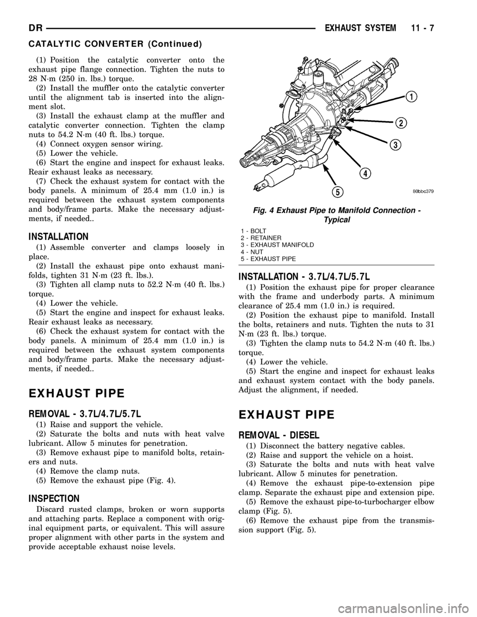
(5) Remove the exhaust pipe (Fig. 4).
INSPECTION
Discard rusted clamps, broken or worn supports
and attaching parts. Replace a component with orig-
inal equipment parts, or equivalent. This will assure
proper alignment with other parts in the system and
provide acceptable exhaust noise levels.
INSTALLATION - 3.7L/4.7L/5.7L
(1) Position the exhaust pipe for proper clearance
with the frame and underbody parts. A minimum
clearance of 25.4 mm (1.0 in.) is required.
(2) Position the exhaust pipe to manifold. Install
the bolts, retainers and nuts. Tighten the nuts to 31
N´m (23 ft. lbs.) torque.
(3) Tighten the clamp nuts to 54.2 N´m (40 ft. lbs.)
torque.
(4) Lower the vehicle.
(5) Start the engine and inspect for exhaust leaks
and exhaust system contact with the body panels.
Adjust the alignment, if needed.
EXHAUST PIPE
REMOVAL - DIESEL
(1) Disconnect the battery negative cables.
(2) Raise and support the vehicle on a hoist.
(3) Saturate the bolts and nuts with heat valve
lubricant. Allow 5 minutes for penetration.
(4) Remove the exhaust pipe-to-extension pipe
clamp. Separate the exhaust pipe and extension pipe.
(5) Remove the exhaust pipe-to-turbocharger elbow
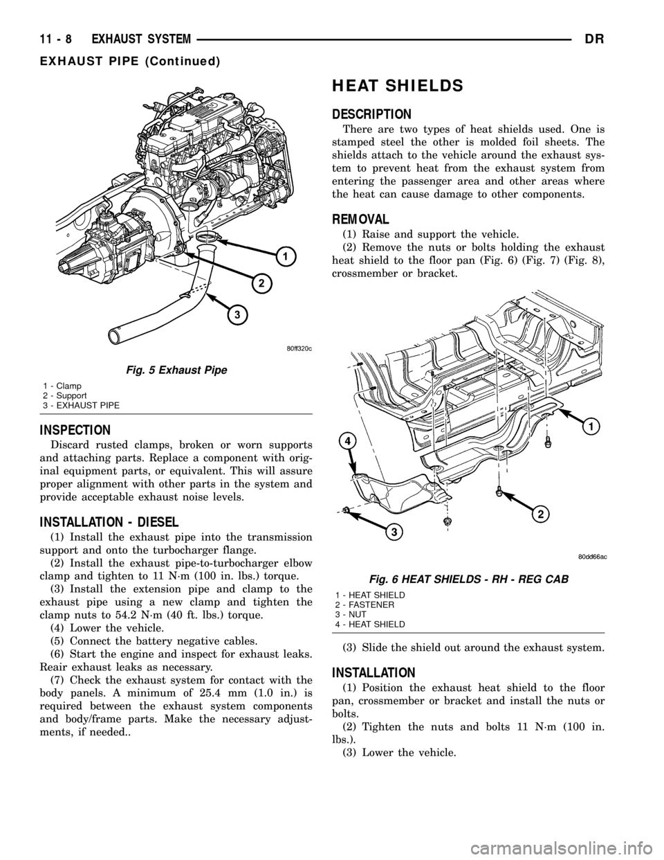
clamp (Fig. 5).
(6) Remove the exhaust pipe from the transmis-
sion support (Fig. 5).
Fig. 4 Exhaust Pipe to Manifold Connection -
Typical
1 - BOLT
2 - RETAINER
3 - EXHAUST MANIFOLD
4 - NUT
5 - EXHAUST PIPE
DREXHAUST SYSTEM 11 - 7
CATALYTIC CONVERTER (Continued)
Page 1533 of 2627
INSPECTION
Discard rusted clamps, broken or worn supports
and attaching parts. Replace a component with orig-
inal equipment parts, or equivalent. This will assure
proper alignment with other parts in the system and
provide acceptable exhaust noise levels.
INSTALLATION - DIESEL
(1) Install the exhaust pipe into the transmission
support and onto the turbocharger flange.
(2) Install the exhaust pipe-to-turbocharger elbow
clamp and tighten to 11 N´m (100 in. lbs.) torque.
(3) Install the extension pipe and clamp to the
exhaust pipe using a new clamp and tighten the
clamp nuts to 54.2 N´m (40 ft. lbs.) torque.
(4) Lower the vehicle.
(5) Connect the battery negative cables.
(6) Start the engine and inspect for exhaust leaks.
Reair exhaust leaks as necessary.
(7) Check the exhaust system for contact with the
body panels. A minimum of 25.4 mm (1.0 in.) is
required between the exhaust system components
and body/frame parts. Make the necessary adjust-
ments, if needed..
HEAT SHIELDS
DESCRIPTION
There are two types of heat shields used. One is
stamped steel the other is molded foil sheets. The
shields attach to the vehicle around the exhaust sys-
tem to prevent heat from the exhaust system from
entering the passenger area and other areas where
the heat can cause damage to other components.
REMOVAL
(1) Raise and support the vehicle.
(2) Remove the nuts or bolts holding the exhaust
heat shield to the floor pan (Fig. 6) (Fig. 7) (Fig. 8),
crossmember or bracket.
(3) Slide the shield out around the exhaust system.
INSTALLATION
(1) Position the exhaust heat shield to the floor
pan, crossmember or bracket and install the nuts or
bolts.
(2) Tighten the nuts and bolts 11 N´m (100 in.
lbs.).
(3) Lower the vehicle.
Fig. 5 Exhaust Pipe
1 - Clamp
2 - Support
3 - EXHAUST PIPE
Fig. 6 HEAT SHIELDS - RH - REG CAB
1 - HEAT SHIELD
2 - FASTENER
3 - NUT
4 - HEAT SHIELD
11 - 8 EXHAUST SYSTEMDR
EXHAUST PIPE (Continued)
Page 1534 of 2627
MUFFLER
REMOVAL
(1) Raise and support the vehicle.
(2) Saturate the clamp nuts with heat valve lubri-
cant. Allow 5 minutes for penetration.
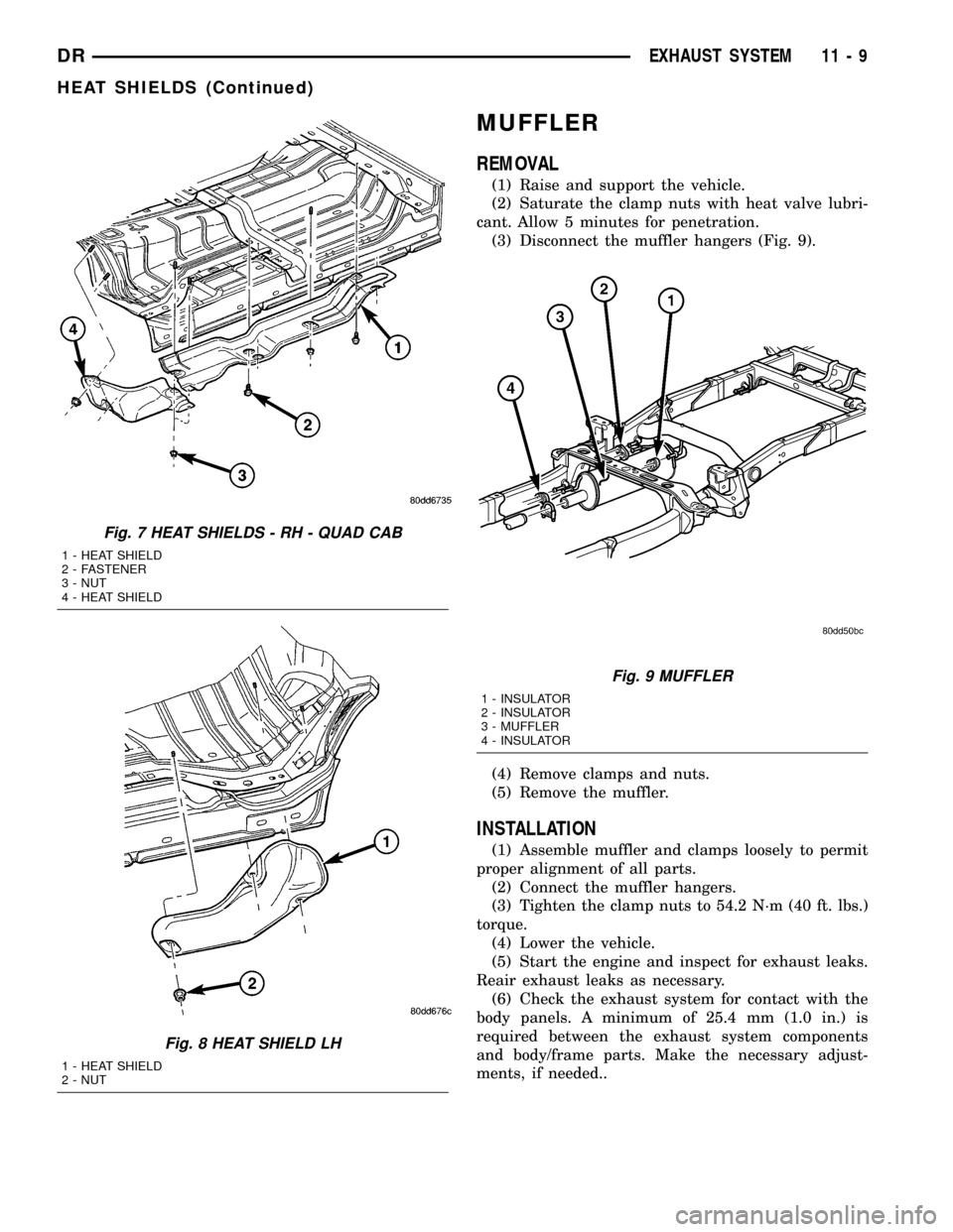
(3) Disconnect the muffler hangers (Fig. 9).
(4) Remove clamps and nuts.
(5) Remove the muffler.
INSTALLATION
(1) Assemble muffler and clamps loosely to permit
proper alignment of all parts.
(2) Connect the muffler hangers.
(3) Tighten the clamp nuts to 54.2 N´m (40 ft. lbs.)
torque.
(4) Lower the vehicle.
(5) Start the engine and inspect for exhaust leaks.
Reair exhaust leaks as necessary.
(6) Check the exhaust system for contact with the
body panels. A minimum of 25.4 mm (1.0 in.) is
required between the exhaust system components
and body/frame parts. Make the necessary adjust-
ments, if needed..
Fig. 7 HEAT SHIELDS - RH - QUAD CAB
1 - HEAT SHIELD
2 - FASTENER
3 - NUT
4 - HEAT SHIELD
Fig. 8 HEAT SHIELD LH
1 - HEAT SHIELD
2 - NUT
Fig. 9 MUFFLER
1 - INSULATOR
2 - INSULATOR
3 - MUFFLER
4 - INSULATOR
DREXHAUST SYSTEM 11 - 9
HEAT SHIELDS (Continued)
Page 1535 of 2627
MUFFLER - 5.9L DIESEL
REMOVAL
(1) Disconnect the battery negative cables.
(2) Raise and support the vehicle.
(3) Remove the muffler to tail pipe and extension
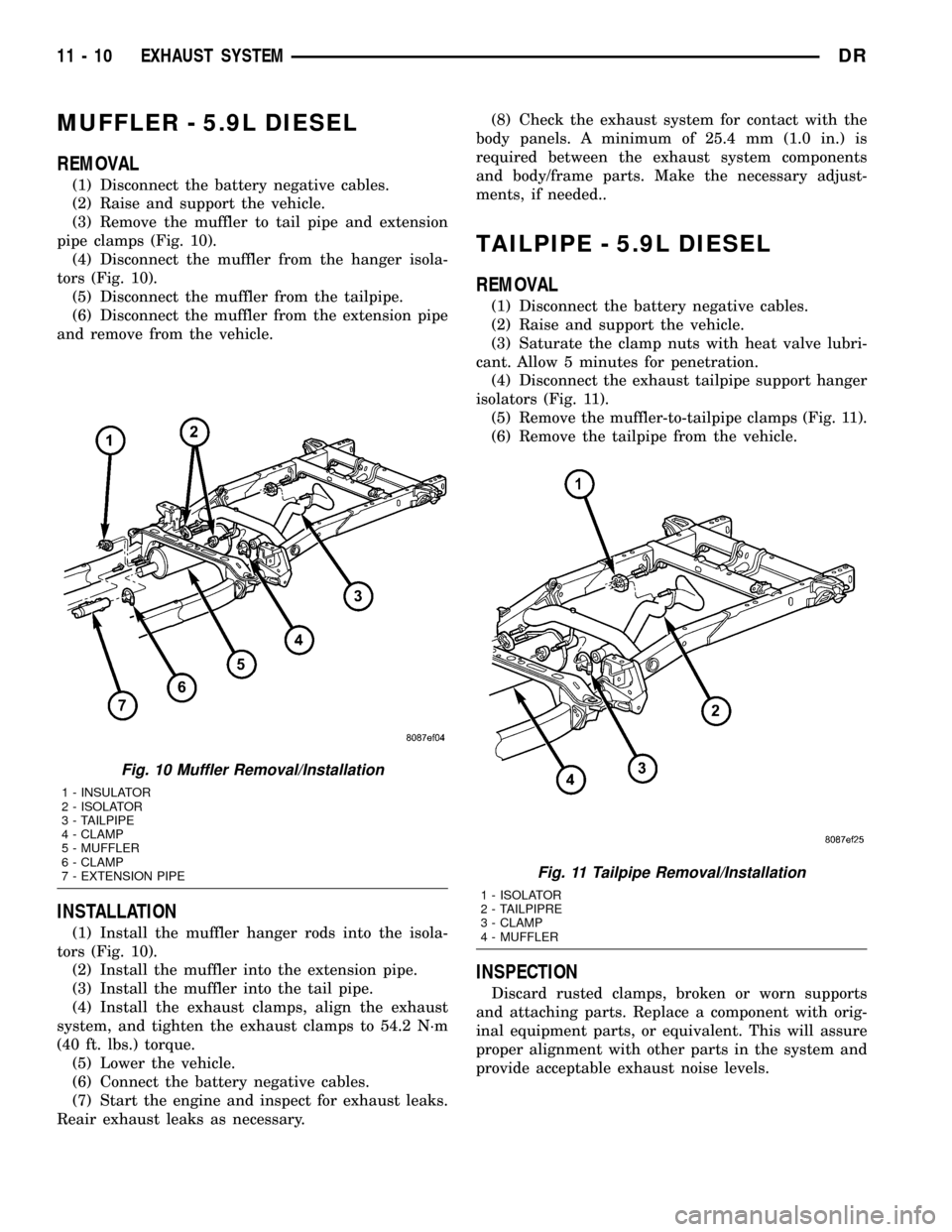
pipe clamps (Fig. 10).
(4) Disconnect the muffler from the hanger isola-
tors (Fig. 10).
(5) Disconnect the muffler from the tailpipe.
(6) Disconnect the muffler from the extension pipe
and remove from the vehicle.
INSTALLATION
(1) Install the muffler hanger rods into the isola-
tors (Fig. 10).
(2) Install the muffler into the extension pipe.
(3) Install the muffler into the tail pipe.
(4) Install the exhaust clamps, align the exhaust
system, and tighten the exhaust clamps to 54.2 N´m
(40 ft. lbs.) torque.
(5) Lower the vehicle.
(6) Connect the battery negative cables.
(7) Start the engine and inspect for exhaust leaks.
Reair exhaust leaks as necessary.(8) Check the exhaust system for contact with the
body panels. A minimum of 25.4 mm (1.0 in.) is
required between the exhaust system components
and body/frame parts. Make the necessary adjust-
ments, if needed..
TAILPIPE - 5.9L DIESEL
REMOVAL
(1) Disconnect the battery negative cables.
(2) Raise and support the vehicle.
(3) Saturate the clamp nuts with heat valve lubri-
cant. Allow 5 minutes for penetration.
(4) Disconnect the exhaust tailpipe support hanger
isolators (Fig. 11).
(5) Remove the muffler-to-tailpipe clamps (Fig. 11).
(6) Remove the tailpipe from the vehicle.
INSPECTION
Discard rusted clamps, broken or worn supports
and attaching parts. Replace a component with orig-
inal equipment parts, or equivalent. This will assure
proper alignment with other parts in the system and
provide acceptable exhaust noise levels.
Fig. 10 Muffler Removal/Installation
1 - INSULATOR
2 - ISOLATOR
3 - TAILPIPE
4 - CLAMP
5 - MUFFLER
6 - CLAMP
7 - EXTENSION PIPE
Fig. 11 Tailpipe Removal/Installation
1 - ISOLATOR
2 - TAILPIPRE
3 - CLAMP
4 - MUFFLER
11 - 10 EXHAUST SYSTEMDR
Page 1536 of 2627
INSTALLATION
(1) Install the tailpipe into the muffler.
(2) Install the tailpipe hanger rods into the isola-
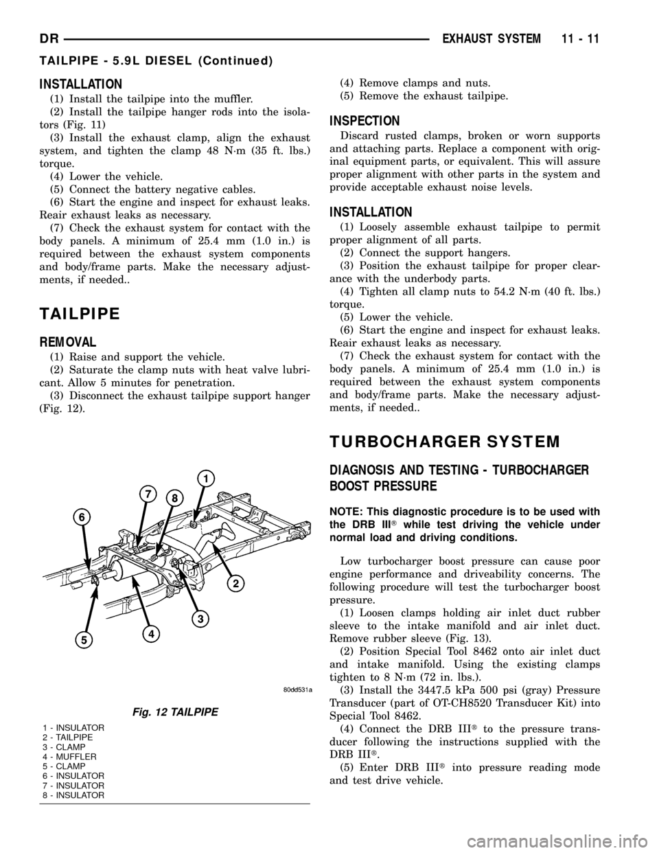
tors (Fig. 11)
(3) Install the exhaust clamp, align the exhaust
system, and tighten the clamp 48 N´m (35 ft. lbs.)
torque.
(4) Lower the vehicle.
(5) Connect the battery negative cables.
(6) Start the engine and inspect for exhaust leaks.
Reair exhaust leaks as necessary.
(7) Check the exhaust system for contact with the
body panels. A minimum of 25.4 mm (1.0 in.) is
required between the exhaust system components
and body/frame parts. Make the necessary adjust-
ments, if needed..
TAILPIPE
REMOVAL
(1) Raise and support the vehicle.
(2) Saturate the clamp nuts with heat valve lubri-
cant. Allow 5 minutes for penetration.
(3) Disconnect the exhaust tailpipe support hanger
(Fig. 12).(4) Remove clamps and nuts.
(5) Remove the exhaust tailpipe.
INSPECTION
Discard rusted clamps, broken or worn supports
and attaching parts. Replace a component with orig-
inal equipment parts, or equivalent. This will assure
proper alignment with other parts in the system and
provide acceptable exhaust noise levels.
INSTALLATION
(1) Loosely assemble exhaust tailpipe to permit
proper alignment of all parts.
(2) Connect the support hangers.
(3) Position the exhaust tailpipe for proper clear-
ance with the underbody parts.
(4) Tighten all clamp nuts to 54.2 N´m (40 ft. lbs.)
torque.
(5) Lower the vehicle.
(6) Start the engine and inspect for exhaust leaks.
Reair exhaust leaks as necessary.
(7) Check the exhaust system for contact with the
body panels. A minimum of 25.4 mm (1.0 in.) is
required between the exhaust system components
and body/frame parts. Make the necessary adjust-
ments, if needed..
TURBOCHARGER SYSTEM
DIAGNOSIS AND TESTING - TURBOCHARGER
BOOST PRESSURE
NOTE: This diagnostic procedure is to be used with
the DRB IIITwhile test driving the vehicle under
normal load and driving conditions.
Low turbocharger boost pressure can cause poor
engine performance and driveability concerns. The
following procedure will test the turbocharger boost
pressure.
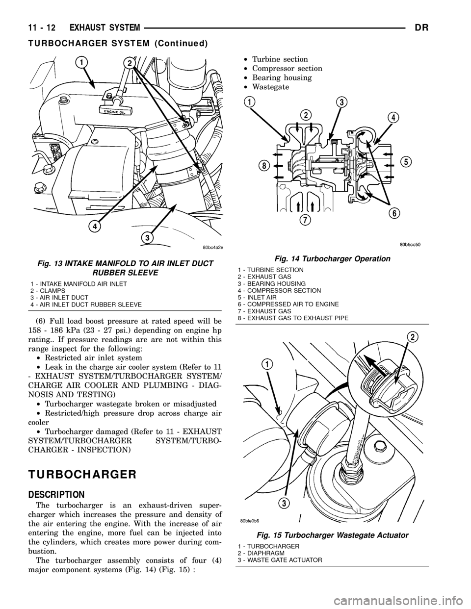
(1) Loosen clamps holding air inlet duct rubber
sleeve to the intake manifold and air inlet duct.
Remove rubber sleeve (Fig. 13).
(2) Position Special Tool 8462 onto air inlet duct
and intake manifold. Using the existing clamps
tighten to 8 N´m (72 in. lbs.).
(3) Install the 3447.5 kPa 500 psi (gray) Pressure
Transducer (part of OT-CH8520 Transducer Kit) into
Special Tool 8462.
(4) Connect the DRB IIItto the pressure trans-
ducer following the instructions supplied with the
DRB IIIt.
(5) Enter DRB IIItinto pressure reading mode
and test drive vehicle.
Fig. 12 TAILPIPE
1 - INSULATOR
2 - TAILPIPE
3 - CLAMP
4 - MUFFLER
5 - CLAMP
6 - INSULATOR
7 - INSULATOR
8 - INSULATOR
DREXHAUST SYSTEM 11 - 11
TAILPIPE - 5.9L DIESEL (Continued)
Page 1537 of 2627
(6) Full load boost pressure at rated speed will be
158 - 186 kPa (23 - 27 psi.) depending on engine hp
rating.. If pressure readings are are not within this
range inspect for the following:
²Restricted air inlet system
²Leak in the charge air cooler system (Refer to 11
- EXHAUST SYSTEM/TURBOCHARGER SYSTEM/
CHARGE AIR COOLER AND PLUMBING - DIAG-
NOSIS AND TESTING)
²Turbocharger wastegate broken or misadjusted
²Restricted/high pressure drop across charge air
cooler
²Turbocharger damaged (Refer to 11 - EXHAUST
SYSTEM/TURBOCHARGER SYSTEM/TURBO-
CHARGER - INSPECTION)
TURBOCHARGER
DESCRIPTION
The turbocharger is an exhaust-driven super-
charger which increases the pressure and density of
the air entering the engine. With the increase of air
entering the engine, more fuel can be injected into
the cylinders, which creates more power during com-
bustion.
The turbocharger assembly consists of four (4)
major component systems (Fig. 14) (Fig. 15) :²Turbine section
²Compressor section
²Bearing housing
²Wastegate
Fig. 13 INTAKE MANIFOLD TO AIR INLET DUCT
RUBBER SLEEVE
1 - INTAKE MANIFOLD AIR INLET
2 - CLAMPS
3 - AIR INLET DUCT
4 - AIR INLET DUCT RUBBER SLEEVE
Fig. 14 Turbocharger Operation
1 - TURBINE SECTION
2 - EXHAUST GAS
3 - BEARING HOUSING
4 - COMPRESSOR SECTION
5 - INLET AIR
6 - COMPRESSED AIR TO ENGINE
7 - EXHAUST GAS
8 - EXHAUST GAS TO EXHAUST PIPE
Fig. 15 Turbocharger Wastegate Actuator
1 - TURBOCHARGER
2 - DIAPHRAGM
3 - WASTE GATE ACTUATOR
11 - 12 EXHAUST SYSTEMDR
TURBOCHARGER SYSTEM (Continued)
Page 1538 of 2627
OPERATION
Exhaust gas pressure and energy drive the tur-
bine, which in turn drives a centrifugal compressor
that compresses the inlet air, and forces the air into
the engine through the charge air cooler and plumb-
ing. Since heat is a by-product of this compression,
the air must pass through a charge air cooler to cool
the incoming air and maintain power and efficiency.
Increasing air flow to the engine provides:
²Improved engine performance
²Lower exhaust smoke density
²Improved operating economy
²Altitude compensation
²Noise reduction.
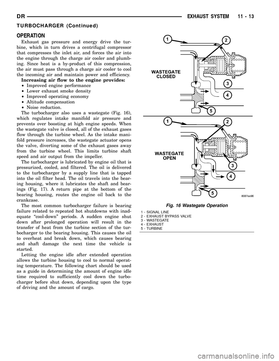
The turbocharger also uses a wastegate (Fig. 16),
which regulates intake manifold air pressure and
prevents over boosting at high engine speeds. When
the wastegate valve is closed, all of the exhaust gases
flow through the turbine wheel. As the intake mani-
fold pressure increases, the wastegate actuator opens
the valve, diverting some of the exhaust gases away
from the turbine wheel. This limits turbine shaft
speed and air output from the impeller.
The turbocharger is lubricated by engine oil that is
pressurized, cooled, and filtered. The oil is delivered
to the turbocharger by a supply line that is tapped
into the oil filter head. The oil travels into the bear-
ing housing, where it lubricates the shaft and bear-
ings (Fig. 17). A return pipe at the bottom of the
bearing housing, routes the engine oil back to the
crankcase.
The most common turbocharger failure is bearing
failure related to repeated hot shutdowns with inad-
equate ªcool-downº periods. A sudden engine shut
down after prolonged operation will result in the
transfer of heat from the turbine section of the tur-
bocharger to the bearing housing. This causes the oil
to overheat and break down, which causes bearing
and shaft damage the next time the vehicle is
started.
Letting the engine idle after extended operation
allows the turbine housing to cool to normal operat-
ing temperature. The following chart should be used
as a guide in determining the amount of engine idle
time required to sufficiently cool down the turbo-
charger before shut down, depending upon the type
of driving and the amount of cargo.
Fig. 16 Wastegate Operation
1 - SIGNAL LINE
2 - EXHAUST BYPASS VALVE
3 - WASTEGATE
4 - EXHAUST
5 - TURBINE
DREXHAUST SYSTEM 11 - 13
TURBOCHARGER (Continued)
Page 1540 of 2627
(9) Remove the turbocharger and gasket from the
exhaust manifold.
(10) If the turbocharger is not to be installed
immediately, cover the opening to prevent material
from entering into the manifold.
(11) If replacing the turbocharger, transfer the tur-
bocharger oil supply fitting to the new assembly.
Tighten fitting to 36 N´m (27 ft. lbs.).
(12) Clean and inspect the sealing surface.
CAUTION: The turbocharger is only serviced as an
assembly. Do not attempt to repair the turbocharger
as turbocharger and/or engine damage can result.
CLEANING
WARNING: To prevent damage or personal injury,
do not use a combustable cleaner to clean the tur-
bocharger.
Clean the turbocharger and exhaust manifold
mounting surfaces with a suitable scraper.
INSPECTION
Visually inspect the turbocharger and exhaust
manifold gasket surfaces. Replace stripped or eroded
mounting studs.
(1) Visually inspect the turbocharger for cracks.
The following cracks are NOT acceptable:
²Cracks in the turbine and compressor housing
that go completely through.
²Cracks in the mounting flange that are longer
than 15 mm (0.6 in.).
²Cracks in the mounting flange that intersect
bolt through-holes.
²Two (2) Cracks in the mounting flange that are
closer than 6.4 mm (0.25 in.) together.
(2) Visually inspect the impeller and compressor
wheel fins for nicks, cracks, or chips. Note: Some
impellers may have a factory placed paint mark
which, after normal operation, appears to be a crack.
Remove this mark with a suitable solvent to verify
that it is not a crack.
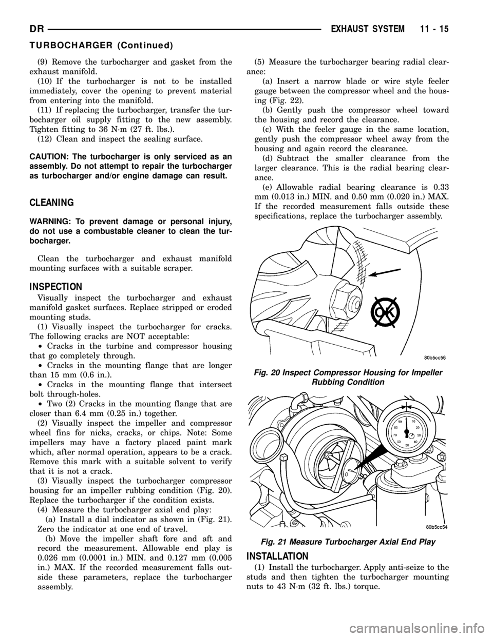
(3) Visually inspect the turbocharger compressor
housing for an impeller rubbing condition (Fig. 20).
Replace the turbocharger if the condition exists.
(4) Measure the turbocharger axial end play:
(a) Install a dial indicator as shown in (Fig. 21).
Zero the indicator at one end of travel.
(b) Move the impeller shaft fore and aft and
record the measurement. Allowable end play is
0.026 mm (0.0001 in.) MIN. and 0.127 mm (0.005
in.) MAX. If the recorded measurement falls out-
side these parameters, replace the turbocharger
assembly.(5) Measure the turbocharger bearing radial clear-
ance:
(a) Insert a narrow blade or wire style feeler
gauge between the compressor wheel and the hous-
ing (Fig. 22).
(b) Gently push the compressor wheel toward
the housing and record the clearance.
(c) With the feeler gauge in the same location,
gently push the compressor wheel away from the
housing and again record the clearance.
(d) Subtract the smaller clearance from the
larger clearance. This is the radial bearing clear-
ance.
(e) Allowable radial bearing clearance is 0.33
mm (0.013 in.) MIN. and 0.50 mm (0.020 in.) MAX.
If the recorded measurement falls outside these
specifications, replace the turbocharger assembly.
INSTALLATION
(1) Install the turbocharger. Apply anti-seize to the
studs and then tighten the turbocharger mounting
nuts to 43 N´m (32 ft. lbs.) torque.
Fig. 20 Inspect Compressor Housing for Impeller
Rubbing Condition
Fig. 21 Measure Turbocharger Axial End Play
DREXHAUST SYSTEM 11 - 15
TURBOCHARGER (Continued)