1998 DODGE RAM 1500 washer fluid
[x] Cancel search: washer fluidPage 1495 of 2627
(6) Remove the wooden dowel rods and rubber
bands from the tappets.
(7) Lubricate the push rods with engine oil and
install in their original location.Verify that they
are seated in the tappets.
(8) Lubricate the valve tips with engine oil and
install the crossheads in their original locations.
(9) Lubricate the crossheads and push rod sockets
with engine oil and install the rocker arms and ped-
estals in their original locations. Tighten bolts to 36
N´m (27 ft. lbs.) torque.
(10)Verify valve lash adjustment (Refer to 9 -
ENGINE/CYLINDER HEAD/INTAKE/EXHAUST
VALVES & SEATS - STANDARD PROCEDURE).
(11) Install the cylinder head cover and reusable
gasket (Refer to 9 - ENGINE/CYLINDER HEAD/
CYLINDER HEAD COVER(S) - INSTALLATION).
(12) Install gear housing cover (Refer to 9 -
ENGINE/VALVE TIMING/GEAR HOUSING COVER
- INSTALLATION). Install front crankshaft dust
seal.
(13) Install the crankshaft damper with the speed
indicator ring (Refer to 9 - ENGINE/ENGINE
BLOCK/VIBRATION DAMPER - INSTALLATION).
(14) Install the fan support/hub assembly Refer to
(Refer to 7 - COOLING/ENGINE/RADIATOR FAN -
INSTALLATION).
(15) Install the power steering pump.
(16) Install accessory drive belt tensioner. Torque
bolt to 43 Nm (32 ft. lbs.).
(17) Install the accessory drive belt (Refer to 7 -
COOLING/ACCESSORY DRIVE/DRIVE BELTS -
INSTALLATION).
(18) Install the charge air cooler (with a/c con-
denser and auxiliary transmission oil cooler, if
equipped) and tighten the mounting bolts to 2 N´m
(17 in. lbs.) torque.
(19) Connect charge air cooler inlet and outlet
pipes. Tighten clamps to 11 N´m (95 in. lbs.) torque.
(20) Install the radiator upper support panel.
(21) Close radiator petcock and lower the radiator
into the engine compartment. Tighten the mounting
bolts to 11 N´m (95 in. lbs.) torque.
(22) Raise vehicle on hoist.
(23) Connect radiator lower hose and install
clamp.
(24) Connect transmission auxiliary oil cooler lines
(if equipped).
(25) Lower vehicle.
(26) Install the fan shroud and tighten the mount-
ing screws to 6 N´m (50 in. lbs.) torque.
(27) Install the electronically controlled viscous
fan/drive assembly. Connect harness connector.(Refer
to 7 - COOLING/ENGINE/RADIATOR FAN -
INSTALLATION).(28) Install the coolant recovery and windshield
washer fluid reservoirs to the fan shroud.
(29) Connect the coolant recovery hose to the radi-
ator filler neck.
(30) Add engine coolant (Refer to 7 - COOLING -
STANDARD PROCEDURE).
(31) Charge A/C system with refrigerant (if A/C
equipped) (Refer to 24 - HEATING & AIR CONDI-
TIONING/PLUMBING - STANDARD PROCEDURE).
(32) Connect the battery negative cables.
(33) Start engine and check for engine oil and cool-
ant leaks.
CONNECTING ROD BEARINGS
STANDARD PROCEDURE - CONNECTING ROD
BEARING AND CRANKSHAFT JOURNAL
CLEARANCE
(1) Measure the connecting rod bore with bearings
removedand the bolts tightened to 100 N´m (73 ft.
lbs.) torque..
(2) Measure the connecting rod bore with the bear-
ingsinstalledand the bolts tightened to 100 N´m
(73 ft. lbs.) torque.
Measure within 20É arc from each side of the part-
ing line. Also measure 90É from parting line.
Record the smallest and largest diameter.
Measure the diameter of the rod journal at the
location shown (Fig. 63). Calculate the average diam-
eter for each side of the journal.
Determine minimum bearing clearance by calculat-
ing the differance between the smallest connecting
rod bore diameter with the bearing installed and the
average diameter for each side of the crankshaft jour-
nal.
Determine the maximum bearing clearance by cal-
culating the difference between the largest connect-
ing rod bore diameter and the average diameter with
the bearing installed for each side of the crankshaft
journal.
DESCRIPTION MEASUREMENT
CONNECTING ROD
BORE, BEARINGS
REMOVEDMIN. 72.99 mm (2.874
in.)
MAX. 73.01 mm (2.875
in.)
CONNECTING ROD
BORE, BEARINGS
INSTALLEDMIN. 69.05 mm (2.719
in.)
MAX. 69.10 mm (2.720
in.)
9 - 272 ENGINE 5.9L DIESELDR
CAMSHAFT & BEARINGS (IN BLOCK) (Continued)
Page 1676 of 2627
(4) Disconnect and cap the fluid hoses from steer-
ing gear (Refer to 19 - STEERING/PUMP/HOSES -
REMOVAL).
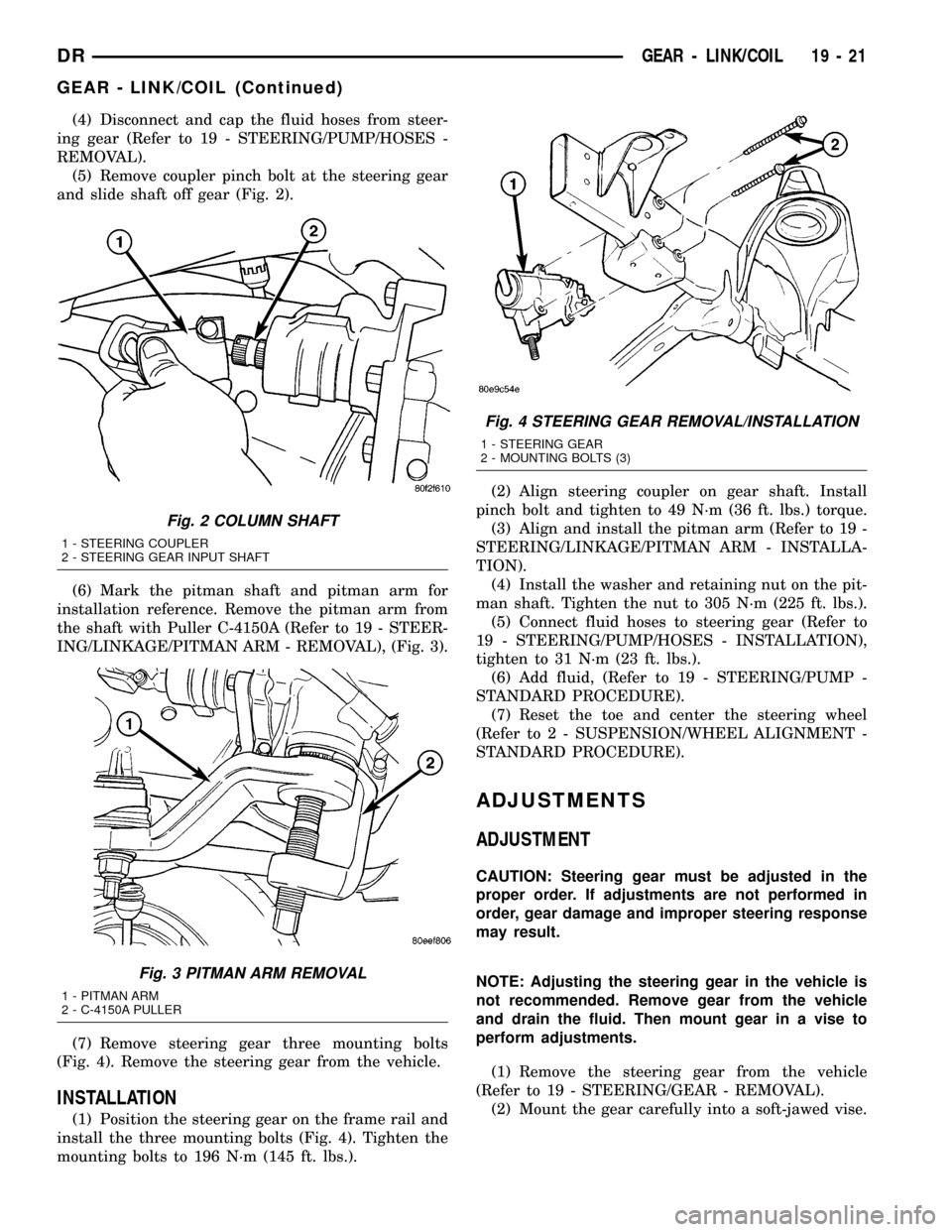
(5) Remove coupler pinch bolt at the steering gear
and slide shaft off gear (Fig. 2).
(6) Mark the pitman shaft and pitman arm for
installation reference. Remove the pitman arm from
the shaft with Puller C-4150A (Refer to 19 - STEER-
ING/LINKAGE/PITMAN ARM - REMOVAL), (Fig. 3).
(7) Remove steering gear three mounting bolts
(Fig. 4). Remove the steering gear from the vehicle.
INSTALLATION
(1) Position the steering gear on the frame rail and
install the three mounting bolts (Fig. 4). Tighten the
mounting bolts to 196 N´m (145 ft. lbs.).(2) Align steering coupler on gear shaft. Install
pinch bolt and tighten to 49 N´m (36 ft. lbs.) torque.
(3) Align and install the pitman arm (Refer to 19 -
STEERING/LINKAGE/PITMAN ARM - INSTALLA-
TION).
(4) Install the washer and retaining nut on the pit-
man shaft. Tighten the nut to 305 N´m (225 ft. lbs.).
(5) Connect fluid hoses to steering gear (Refer to
19 - STEERING/PUMP/HOSES - INSTALLATION),
tighten to 31 N´m (23 ft. lbs.).
(6) Add fluid, (Refer to 19 - STEERING/PUMP -
STANDARD PROCEDURE).
(7) Reset the toe and center the steering wheel
(Refer to 2 - SUSPENSION/WHEEL ALIGNMENT -
STANDARD PROCEDURE).
ADJUSTMENTS
ADJUSTMENT
CAUTION: Steering gear must be adjusted in the
proper order. If adjustments are not performed in
order, gear damage and improper steering response
may result.
NOTE: Adjusting the steering gear in the vehicle is
not recommended. Remove gear from the vehicle
and drain the fluid. Then mount gear in a vise to
perform adjustments.
(1) Remove the steering gear from the vehicle
(Refer to 19 - STEERING/GEAR - REMOVAL).
(2) Mount the gear carefully into a soft-jawed vise.
Fig. 2 COLUMN SHAFT
1 - STEERING COUPLER
2 - STEERING GEAR INPUT SHAFT
Fig. 3 PITMAN ARM REMOVAL
1 - PITMAN ARM
2 - C-4150A PULLER
Fig. 4 STEERING GEAR REMOVAL/INSTALLATION
1 - STEERING GEAR
2 - MOUNTING BOLTS (3)
DRGEAR - LINK/COIL 19 - 21
GEAR - LINK/COIL (Continued)
Page 1869 of 2627

(33) Remove tools and remove servo piston and
spring.
(34) Compress rear servo piston with C-clamp and
Tool C-4470, or Valve Spring Compressor C-3422-B
(Fig. 39). Compress servo spring retainer only
enough to permit snap-ring removal.
(35) Remove servo piston snap-ring (Fig. 39). Start
one end of ring out of bore. Then carefully work
removal tool around back of snap-ring until free of
ring groove.Exercise caution when removing
snap-ring. Servo bore can be scratched or
nicked if care is not exercised.
(36) Remove tools and remove rear servo retainer,
spring and piston assembly.
CLEANING
Clean the case in a solvent tank. Flush the case
bores and fluid passages thoroughly with solvent.
Dry the case and all fluid passages with compressed
air. Be sure all solvent is removed from the case and
that all fluid passages are clear.
NOTE: Do not use shop towels or rags to dry the
case (or any other transmission component) unless
they are made from lint-free materials. Lint will stick
to case surfaces and transmission components and
circulate throughout the transmission after assem-
bly. A sufficient quantity of lint can block fluid pas-
sages and interfere with valve body operation.
Lubricate transmission parts with MopartATF +4,
Automatic Transmission fluid, during overhaul and
assembly. Use petroleum jelly to prelubricate seals,
O-rings, and thrust washers. Petroleum jelly can also
be used to hold parts in place during reassembly.
INSPECTION
Inspect the case for cracks, porous spots, worn
bores, or damaged threads. Damaged threads can be
repaired with Helicoil thread inserts. However, the
case will have to be replaced if it exhibits any type of
damage or wear.
Lubricate the front band adjusting screw threads
with petroleum jelly and thread the screw part-way
into the case. Be sure the screw turns freely.
Inspect the transmission bushings during overhaul.
Bushing condition is important as worn, scored bush-
ings contribute to low pressures, clutch slip and
accelerated wear of other components. However, do
not replace bushings as a matter of course. Replace
bushings only when they are actually worn, or
scored.
The use of crocus cloth is permissible where neces-
sary, providing it is used carefully. When used on
shafts, or valves, use extreme care to avoid rounding
off sharp edges. Sharp edges are vital as they pre-
vent foreign matter from getting between the valve
and valve bore.
Do not reuse oil seals, gaskets, seal rings, or
O-rings during overhaul. Replace these parts as a
matter of course. Also do not reuse snap rings or
E-clips that are bent or distorted. Replace these parts
as well.
ASSEMBLY
Do not allow dirt, grease, or foreign material to
enter the case or transmission components during
assembly. Keep the transmission case and compo-
nents clean. Also make sure the tools and workbench
area used for reassembly operations are equally
clean.
Shop towels used for wiping off tools and your
hands must be made fromlint freematerials. Lint
will stick to transmission parts and could interfere
with valve operation or even restrict fluid passages.
Lubricate transmission clutch and gear compo-
nents with MopartATF +4 during reassembly. Soak
clutch discs in transmission fluid before installation.
Use petroleum jelly on piston seals and o-rings to
ease installation. Petroleum jelly can also be used to
lubricate and hold thrust washers and plates in posi-
tion during assembly.
Do not use chassis grease, bearing grease,
white grease, or similar lubricants on any part.
These types of lubricants can eventually block or
restrict fluid passages and valve operation. Use
petroleum jelly only.
Do not force parts into place. The transmission
components and sub-assemblies are easily installed
by hand when properly aligned. If a part seems dif-
ficult to install, it is either misaligned or incorrectly
Fig. 39 Rear Servo Retaining Snap-Ring
1 - TOOL C-4470
2 - C-CLAMP
3 - REAR SERVO SPRING RETAINER
4 - RETAINER SNAP-RING
21 - 166 AUTOMATIC TRANSMISSION - 48REDR
AUTOMATIC TRANSMISSION - 48RE (Continued)
Page 1870 of 2627
assembled. Verify that thrust washers, thrust plates
and seal rings are correctly positioned.
The planetary geartrain, front/rear clutch assem-
blies and oil pump are all much easier to install
when the transmission case is upright. Either tilt the
case upward with wood blocks, or cut a hole in the
bench large enough for the intermediate shaft and
rear support. Then lower the shaft and support into
the hole and support the rear of the case directly on
the bench.
FRONT/REAR SERVO
(1) Lubricate rear servo piston seal with ATF +4.
Lubricate servo bore in case with ATF +4.
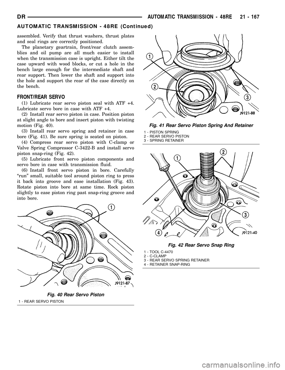
(2) Install rear servo piston in case. Position piston
at slight angle to bore and insert piston with twisting
motion (Fig. 40).
(3) Install rear servo spring and retainer in case
bore (Fig. 41). Be sure spring is seated on piston.
(4) Compress rear servo piston with C-clamp or
Valve Spring Compressor C-3422-B and install servo
piston snap-ring (Fig. 42).
(5) Lubricate front servo piston components and
servo bore in case with transmission fluid.
(6) Install front servo piston in bore. Carefully
ªrunº small, suitable tool around piston ring to press
it back into groove and ease installation (Fig. 43).
Rotate piston into bore at same time. Rock piston
slightly to ease piston ring past snap-ring groove and
into bore.
Fig. 40 Rear Servo Piston
1 - REAR SERVO PISTON
Fig. 41 Rear Servo Piston Spring And Retainer
1 - PISTON SPRING
2 - REAR SERVO PISTON
3 - SPRING RETAINER
Fig. 42 Rear Servo Snap Ring
1 - TOOL C-4470
2 - C-CLAMP
3 - REAR SERVO SPRING RETAINER
4 - RETAINER SNAP-RING
DRAUTOMATIC TRANSMISSION - 48RE 21 - 167
AUTOMATIC TRANSMISSION - 48RE (Continued)
Page 1874 of 2627
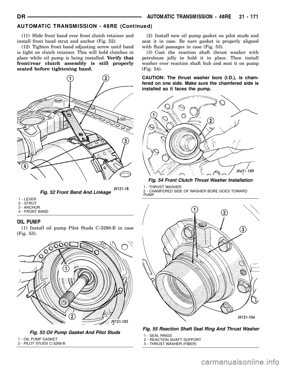
(11) Slide front band over front clutch retainer and
install front band strut and anchor (Fig. 52).
(12) Tighten front band adjusting screw until band
is tight on clutch retainer. This will hold clutches in
place while oil pump is being installed.Verify that
front/rear clutch assembly is still properly
seated before tightening band.
OIL PUMP
(1) Install oil pump Pilot Studs C-3288-B in case
(Fig. 53).(2) Install new oil pump gasket on pilot studs and
seat it in case. Be sure gasket is properly aligned
with fluid passages in case (Fig. 53).
(3) Coat the reaction shaft thrust washer with
petroleum jelly to hold it in place. Then install
washer over reaction shaft hub and seat it on pump
(Fig. 54).
CAUTION: The thrust washer bore (I.D.), is cham-
fered on one side. Make sure the chamfered side is
installed so it faces the pump.
Fig. 53 Oil Pump Gasket And Pilot Studs
1 - OIL PUMP GASKET
2 - PILOT STUDS C-3288-B
Fig. 54 Front Clutch Thrust Washer Installation
1 - THRUST WASHER
2 - CHAMFERED SIDE OF WASHER BORE GOES TOWARD
PUMP
Fig. 55 Reaction Shaft Seal Ring And Thrust Washer
1 - SEAL RINGS
2 - REACTION SHAFT SUPPORT
3 - THRUST WASHER (FIBER)
Fig. 52 Front Band And Linkage
1 - LEVER
2 - STRUT
3 - ANCHOR
4 - FRONT BAND
DRAUTOMATIC TRANSMISSION - 48RE 21 - 171
AUTOMATIC TRANSMISSION - 48RE (Continued)
Page 1892 of 2627
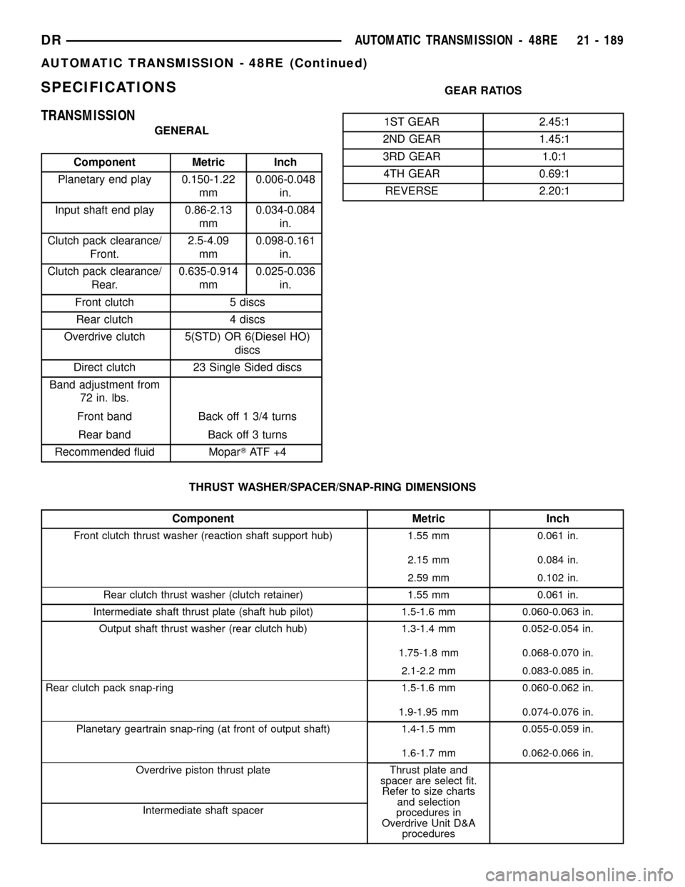
SPECIFICATIONS
TRANSMISSION
GENERAL
Component Metric Inch
Planetary end play 0.150-1.22
mm0.006-0.048
in.
Input shaft end play 0.86-2.13
mm0.034-0.084
in.
Clutch pack clearance/
Front.2.5-4.09
mm0.098-0.161
in.
Clutch pack clearance/
Rear.0.635-0.914
mm0.025-0.036
in.
Front clutch 5 discs
Rear clutch 4 discs
Overdrive clutch 5(STD) OR 6(Diesel HO)
discs
Direct clutch 23 Single Sided discs
Band adjustment from
72 in. lbs.
Front band Back off 1 3/4 turns
Rear band Back off 3 turns
Recommended fluid MoparTAT F + 4GEAR RATIOS
1ST GEAR 2.45:1
2ND GEAR 1.45:1
3RD GEAR 1.0:1
4TH GEAR 0.69:1
REVERSE 2.20:1
THRUST WASHER/SPACER/SNAP-RING DIMENSIONS
Component Metric Inch
Front clutch thrust washer (reaction shaft support hub) 1.55 mm 0.061 in.
2.15 mm 0.084 in.
2.59 mm 0.102 in.
Rear clutch thrust washer (clutch retainer) 1.55 mm 0.061 in.
Intermediate shaft thrust plate (shaft hub pilot) 1.5-1.6 mm 0.060-0.063 in.
Output shaft thrust washer (rear clutch hub) 1.3-1.4 mm 0.052-0.054 in.
1.75-1.8 mm 0.068-0.070 in.
2.1-2.2 mm 0.083-0.085 in.
Rear clutch pack snap-ring 1.5-1.6 mm 0.060-0.062 in.
1.9-1.95 mm 0.074-0.076 in.
Planetary geartrain snap-ring (at front of output shaft) 1.4-1.5 mm 0.055-0.059 in.
1.6-1.7 mm 0.062-0.066 in.
Overdrive piston thrust plate Thrust plate and
spacer are select fit.
Refer to size charts
and selection
procedures in
Overdrive Unit D&A
procedures Intermediate shaft spacer
DRAUTOMATIC TRANSMISSION - 48RE 21 - 189
AUTOMATIC TRANSMISSION - 48RE (Continued)
Page 1916 of 2627

OIL PUMP
DESCRIPTION
The oil pump (Fig. 109) is located in the pump
housing inside the bell housing of the transmission
case. The oil pump consists of an inner and outer
gear, a housing, and a reaction shaft support.
OPERATION
As the torque converter rotates, the converter hub
rotates the inner and outer gears. As the gears
rotate, the clearance between the gear teeth
increases in the crescent area, and creates a suction
at the inlet side of the pump. This suction draws
fluid through the pump inlet from the oil pan. As the
clearance between the gear teeth in the crescent area
decreases, it forces pressurized fluid into the pump
outlet and to the valve body.
Fig. 109 Oil Pump Assembly
1 - OIL SEAL 7 - BOLTS (6)
2 - VENT BAFFLE 8 - #1 THRUST WASHER (SELECTIVE)
3 - OIL PUMP BODY 9 - INNER GEAR
4 - GASKET 10 - OUTER GEAR
5 - REACTION SHAFT SUPPORT 11 - ªOº RING
6 - SEAL RINGS 12 - TORQUE CONVERTER SEAL RING
DRAUTOMATIC TRANSMISSION - 48RE 21 - 213
Page 1917 of 2627
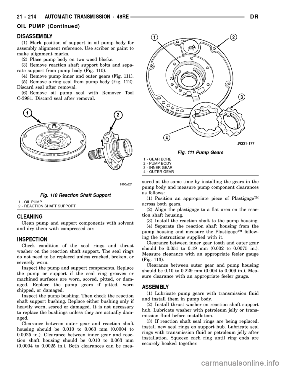
DISASSEMBLY
(1) Mark position of support in oil pump body for
assembly alignment reference. Use scriber or paint to
make alignment marks.
(2) Place pump body on two wood blocks.
(3) Remove reaction shaft support bolts and sepa-
rate support from pump body (Fig. 110).
(4) Remove pump inner and outer gears (Fig. 111).
(5) Remove o-ring seal from pump body (Fig. 112).
Discard seal after removal.
(6) Remove oil pump seal with Remover Tool
C-3981. Discard seal after removal.
CLEANING
Clean pump and support components with solvent
and dry them with compressed air.
INSPECTION
Check condition of the seal rings and thrust
washer on the reaction shaft support. The seal rings
do not need to be replaced unless cracked, broken, or
severely worn.
Inspect the pump and support components. Replace
the pump or support if the seal ring grooves or
machined surfaces are worn, scored, pitted, or dam-
aged. Replace the pump gears if pitted, worn
chipped, or damaged.
Inspect the pump bushing. Then check the reaction
shaft support bushing. Replace either bushing only if
heavily worn, scored or damaged. It is not necessary
to replace the bushings unless they are actually dam-
aged.
Clearance between outer gear and reaction shaft
housing should be 0.010 to 0.063 mm (0.0004 to
0.0025 in.). Clearance between inner gear and reac-
tion shaft housing should be 0.010 to 0.063 mm
(0.0004 to 0.0025 in.). Both clearances can be mea-sured at the same time by installing the gears in the
pump body and measure pump component clearances
as follows:
(1) Position an appropriate piece of PlastigageŸ
across both gears.
(2) Align the plastigage to a flat area on the reac-
tion shaft housing.
(3) Install the reaction shaft to the pump housing.
(4) Separate the reaction shaft housing from the
pump housing and measure the PlastigageŸ follow-
ing the instructions supplied with it.
Clearance between inner gear tooth and outer gear
should be 0.051 to 0.19 mm (0.002 to 0.0075 in.).
Measure clearance with an appropriate feeler gauge
(Fig. 113).
Clearance between outer gear and pump housing
should be 0.10 to 0.229 mm (0.004 to 0.009 in.). Mea-
sure clearance with an appropriate feeler gauge.
ASSEMBLY
(1) Lubricate pump gears with transmission fluid
and install them in pump body.
(2) Install thrust washer on reaction shaft support
hub. Lubricate washer with petroleum jelly or trans-
mission fluid before installation.
(3) If reaction shaft seal rings are being replaced,
install new seal rings on support hub. Lubricate seal
rings with transmission fluid or petroleum jelly after
installation. Squeeze each ring until ring ends are
securely hooked together.
Fig. 110 Reaction Shaft Support
1 - OIL PUMP
2 - REACTION SHAFT SUPPORT
Fig. 111 Pump Gears
1 - GEAR BORE
2 - PUMP BODY
3 - INNER GEAR
4 - OUTER GEAR
21 - 214 AUTOMATIC TRANSMISSION - 48REDR
OIL PUMP (Continued)