1998 DODGE RAM 1500 Removal
[x] Cancel search: RemovalPage 1565 of 2627
SPECIFICATIONS - TORQUE
TORQUE SPECIFICATIONS
DESCRIPTION N´m Ft. Lbs. In. Lbs.
Cab mount bolts 81 60 Ð
Cargo box bolts 108 80 Ð
Front crossmember bolts - 2WD (light duty only) 61 45 Ð
Front crossmember bolts - 2WD (heavy duty only) 75 55 Ð
Front crossmember bolts - 4WD (light duty only) 102 75 Ð
Front skid plate bolts 34 25 Ð
Lower bumper support bracket bolt 54 40 Ð
Radiator crossmember bolts - lower 28 21 Ð
Radiator crossmember bolts - upper 28 21 Ð
Rear crossmember (light duty only) 102 75 Ð
Rear crossmember (heavy duty only) 115 85 Ð
Rear spring shackle bolts 163 120 Ð
Spare tire winch bolts 41 30 Ð
Trailer hitch reinforcement bracket bolt 170 125 Ð
Transfercase skid plate bolts 34 25 Ð
Transercase skid plate crossmember bolts 34 25 Ð
Transmission mount to crossmember nuts 54 40 Ð
FRONT CROSSMEMBER
REMOVAL
(1) Raise and support the vehicle. (Refer to
LUBRICATION & MAINTENANCE/HOISTING -
STANDARD PROCEDURE)
(2) Remove the front skid plate, if equipped. (Refer
to 13 - FRAME & BUMPERS/FRAME/FRONT SKID
PLATE - REMOVAL)
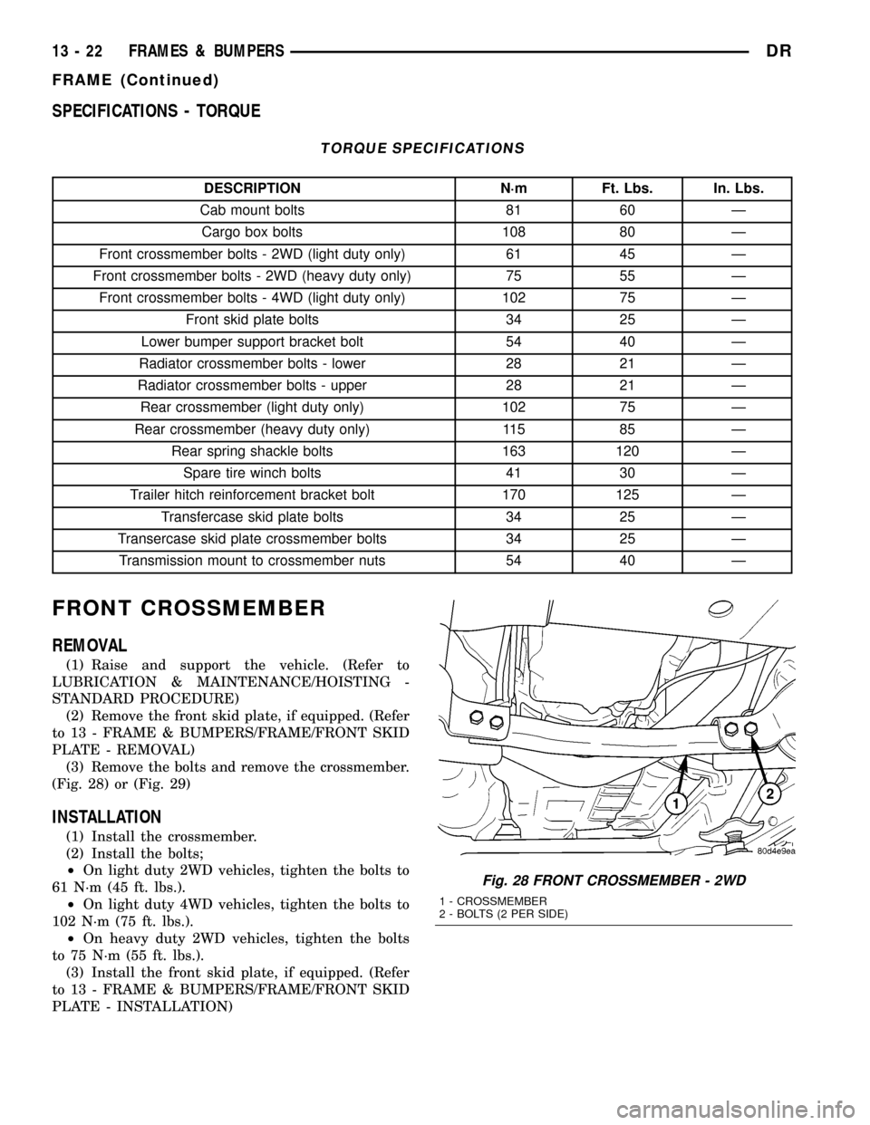
(3) Remove the bolts and remove the crossmember.
(Fig. 28) or (Fig. 29)
INSTALLATION
(1) Install the crossmember.
(2) Install the bolts;
²On light duty 2WD vehicles, tighten the bolts to
61 N´m (45 ft. lbs.).
²On light duty 4WD vehicles, tighten the bolts to
102 N´m (75 ft. lbs.).
²On heavy duty 2WD vehicles, tighten the bolts
to 75 N´m (55 ft. lbs.).
(3) Install the front skid plate, if equipped. (Refer
to 13 - FRAME & BUMPERS/FRAME/FRONT SKID
PLATE - INSTALLATION)
Fig. 28 FRONT CROSSMEMBER - 2WD
1 - CROSSMEMBER
2 - BOLTS (2 PER SIDE)
13 - 22 FRAMES & BUMPERSDR
FRAME (Continued)
Page 1566 of 2627
FRONT SKID PLATE
REMOVAL
(1) Raise and support the vehicle. (Refer to
LUBRICATION & MAINTENANCE/HOISTING -
STANDARD PROCEDURE)
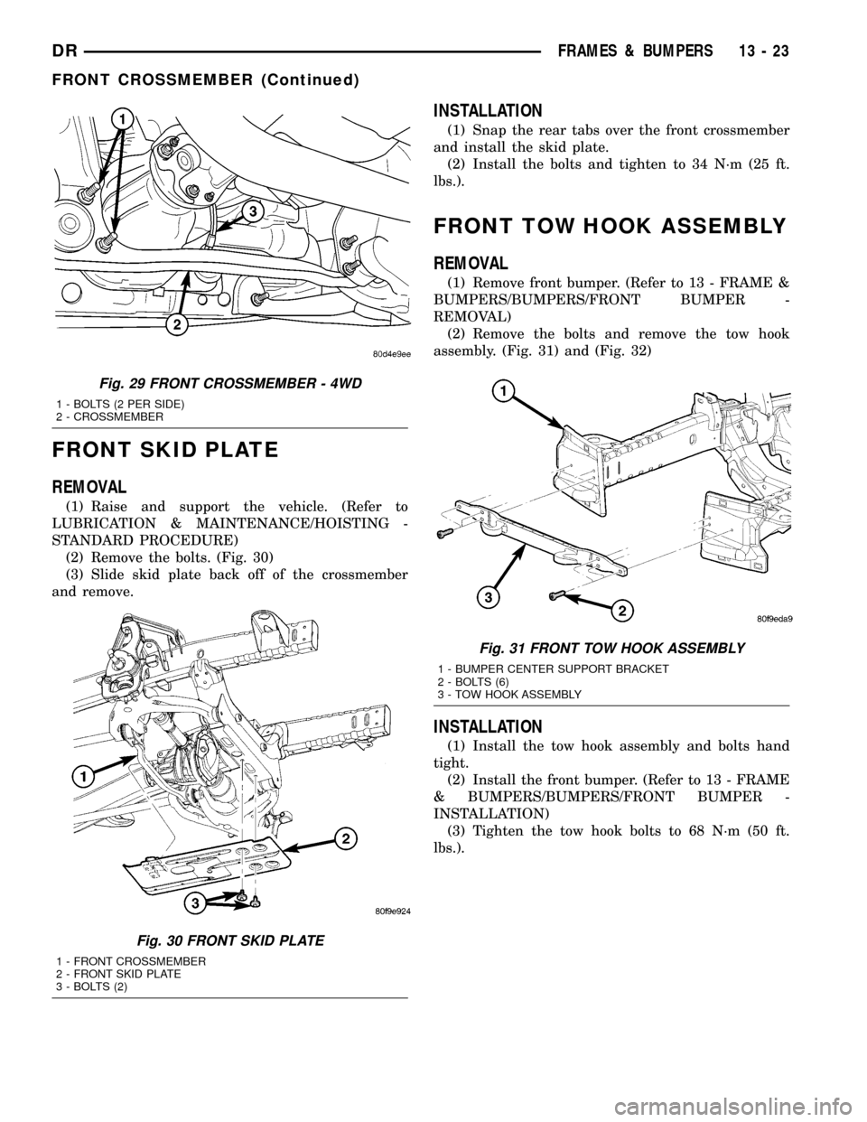
(2) Remove the bolts. (Fig. 30)
(3) Slide skid plate back off of the crossmember
and remove.
INSTALLATION
(1) Snap the rear tabs over the front crossmember
and install the skid plate.
(2) Install the bolts and tighten to 34 N´m (25 ft.
lbs.).
FRONT TOW HOOK ASSEMBLY
REMOVAL
(1) Remove front bumper. (Refer to 13 - FRAME &
BUMPERS/BUMPERS/FRONT BUMPER -
REMOVAL)
(2) Remove the bolts and remove the tow hook
assembly. (Fig. 31) and (Fig. 32)
INSTALLATION
(1) Install the tow hook assembly and bolts hand
tight.
(2) Install the front bumper. (Refer to 13 - FRAME
& BUMPERS/BUMPERS/FRONT BUMPER -
INSTALLATION)
(3) Tighten the tow hook bolts to 68 N´m (50 ft.
lbs.).
Fig. 29 FRONT CROSSMEMBER - 4WD
1 - BOLTS (2 PER SIDE)
2 - CROSSMEMBER
Fig. 30 FRONT SKID PLATE
1 - FRONT CROSSMEMBER
2 - FRONT SKID PLATE
3 - BOLTS (2)
Fig. 31 FRONT TOW HOOK ASSEMBLY
1 - BUMPER CENTER SUPPORT BRACKET
2 - BOLTS (6)
3 - TOW HOOK ASSEMBLY
DRFRAMES & BUMPERS 13 - 23
FRONT CROSSMEMBER (Continued)
Page 1567 of 2627
TRANSMISSION
CROSSMEMBER
REMOVAL
(1) Raise and support the vehicle. (Refer to
LUBRICATION & MAINTENANCE/HOISTING -
STANDARD PROCEDURE)
(2) Remove the transfercase skid plate, if
equipped. (Refer to 13 - FRAME & BUMPERS/
FRAME/TRANSFER CASE SKID PLATE -
REMOVAL)
(3) Support the transmission with a suitable lifting
device.
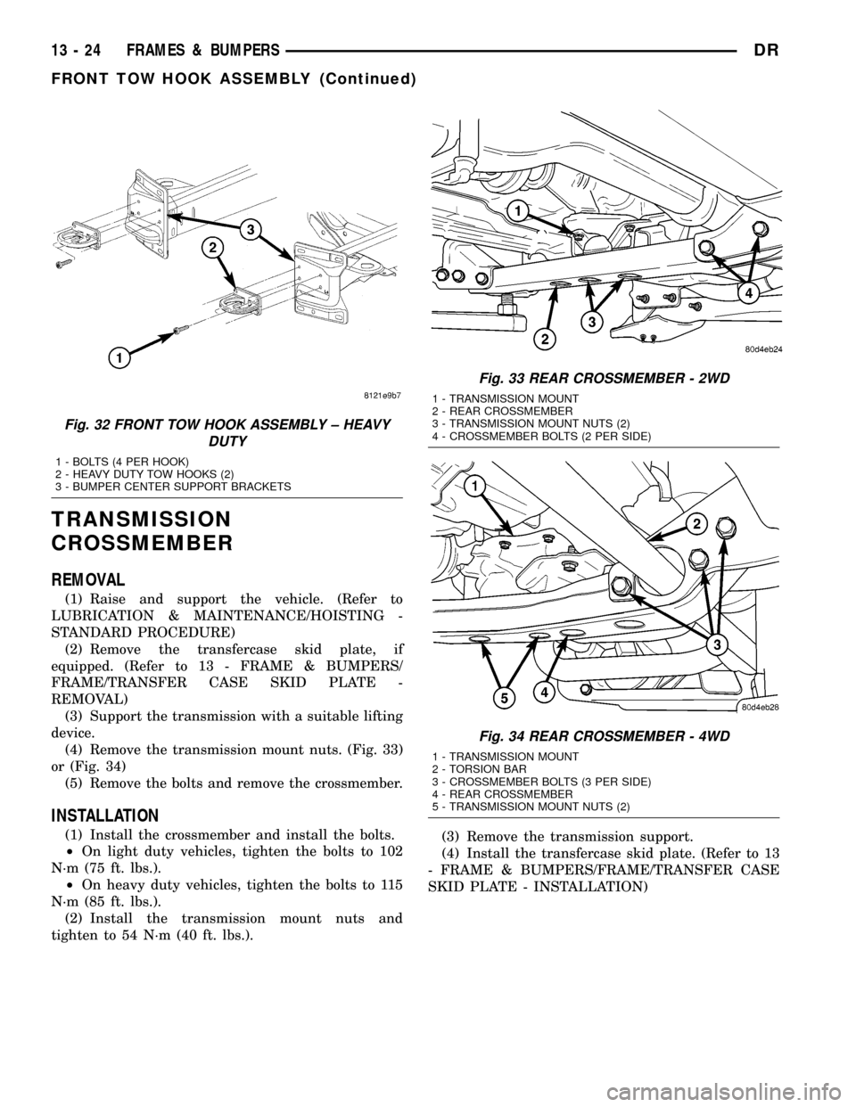
(4) Remove the transmission mount nuts. (Fig. 33)
or (Fig. 34)
(5) Remove the bolts and remove the crossmember.
INSTALLATION
(1) Install the crossmember and install the bolts.
²On light duty vehicles, tighten the bolts to 102
N´m (75 ft. lbs.).
²On heavy duty vehicles, tighten the bolts to 115
N´m (85 ft. lbs.).
(2) Install the transmission mount nuts and
tighten to 54 N´m (40 ft. lbs.).(3) Remove the transmission support.
(4) Install the transfercase skid plate. (Refer to 13
- FRAME & BUMPERS/FRAME/TRANSFER CASE
SKID PLATE - INSTALLATION)
Fig. 32 FRONT TOW HOOK ASSEMBLY ± HEAVY
DUTY
1 - BOLTS (4 PER HOOK)
2 - HEAVY DUTY TOW HOOKS (2)
3 - BUMPER CENTER SUPPORT BRACKETS
Fig. 33 REAR CROSSMEMBER - 2WD
1 - TRANSMISSION MOUNT
2 - REAR CROSSMEMBER
3 - TRANSMISSION MOUNT NUTS (2)
4 - CROSSMEMBER BOLTS (2 PER SIDE)
Fig. 34 REAR CROSSMEMBER - 4WD
1 - TRANSMISSION MOUNT
2 - TORSION BAR
3 - CROSSMEMBER BOLTS (3 PER SIDE)
4 - REAR CROSSMEMBER
5 - TRANSMISSION MOUNT NUTS (2)
13 - 24 FRAMES & BUMPERSDR
FRONT TOW HOOK ASSEMBLY (Continued)
Page 1568 of 2627
TRAILER HITCH
REMOVAL
(1) Remove the rear bumper. (Refer to 13 -
FRAME & BUMPERS/BUMPERS/REAR BUMPER -
REMOVAL)
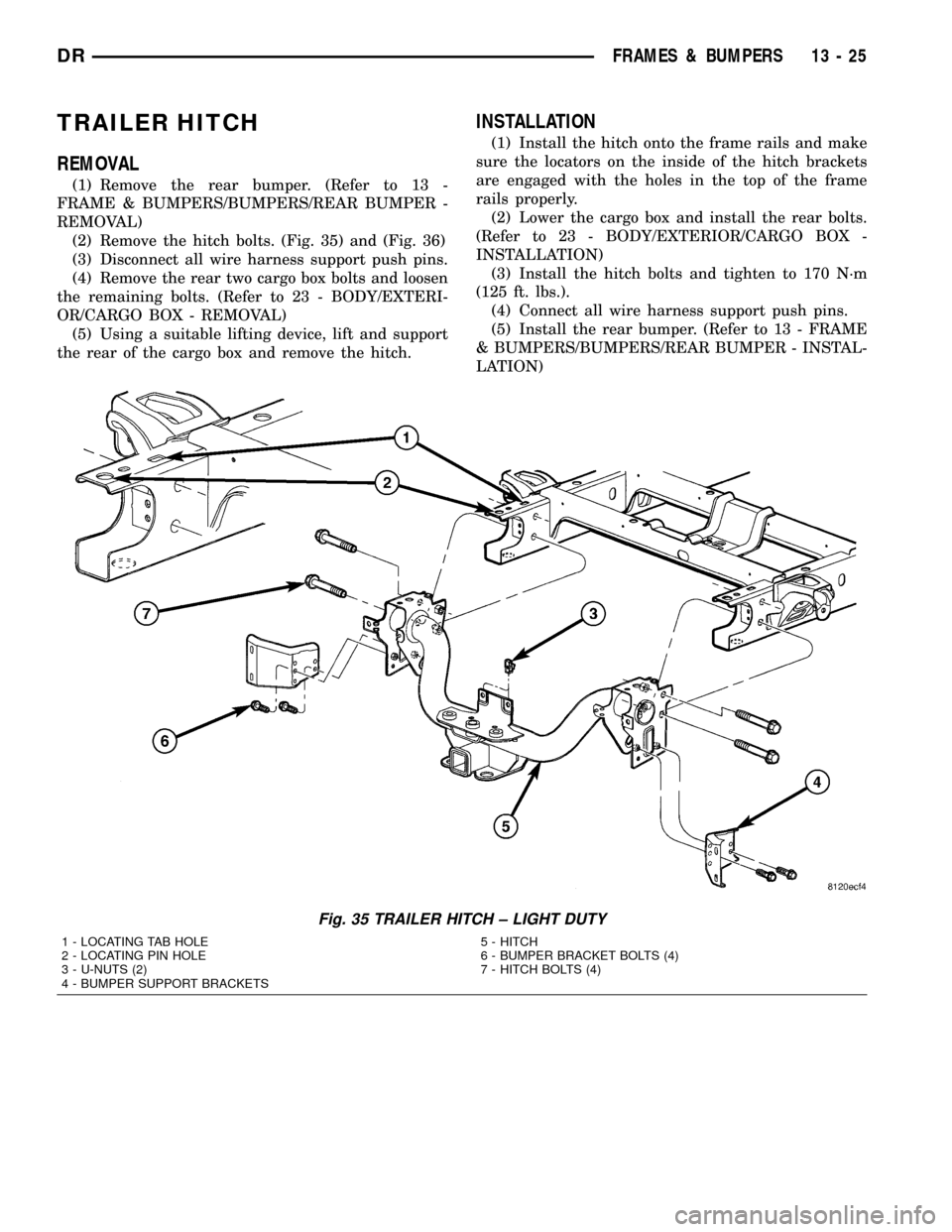
(2) Remove the hitch bolts. (Fig. 35) and (Fig. 36)
(3) Disconnect all wire harness support push pins.
(4) Remove the rear two cargo box bolts and loosen
the remaining bolts. (Refer to 23 - BODY/EXTERI-
OR/CARGO BOX - REMOVAL)
(5) Using a suitable lifting device, lift and support
the rear of the cargo box and remove the hitch.
INSTALLATION
(1) Install the hitch onto the frame rails and make
sure the locators on the inside of the hitch brackets
are engaged with the holes in the top of the frame
rails properly.
(2) Lower the cargo box and install the rear bolts.
(Refer to 23 - BODY/EXTERIOR/CARGO BOX -
INSTALLATION)
(3) Install the hitch bolts and tighten to 170 N´m
(125 ft. lbs.).
(4) Connect all wire harness support push pins.
(5) Install the rear bumper. (Refer to 13 - FRAME
& BUMPERS/BUMPERS/REAR BUMPER - INSTAL-
LATION)
Fig. 35 TRAILER HITCH ± LIGHT DUTY
1 - LOCATING TAB HOLE
2 - LOCATING PIN HOLE
3 - U-NUTS (2)
4 - BUMPER SUPPORT BRACKETS5 - HITCH
6 - BUMPER BRACKET BOLTS (4)
7 - HITCH BOLTS (4)
DRFRAMES & BUMPERS 13 - 25
Page 1569 of 2627
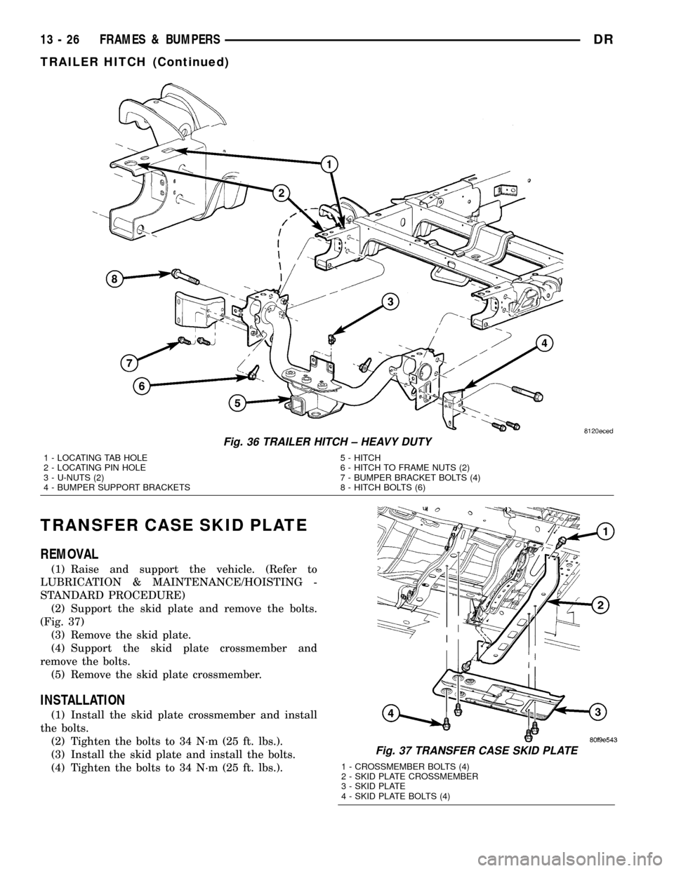
TRANSFER CASE SKID PLATE
REMOVAL
(1) Raise and support the vehicle. (Refer to
LUBRICATION & MAINTENANCE/HOISTING -
STANDARD PROCEDURE)
(2) Support the skid plate and remove the bolts.
(Fig. 37)
(3) Remove the skid plate.
(4) Support the skid plate crossmember and
remove the bolts.
(5) Remove the skid plate crossmember.
INSTALLATION
(1) Install the skid plate crossmember and install
the bolts.
(2) Tighten the bolts to 34 N´m (25 ft. lbs.).
(3) Install the skid plate and install the bolts.
(4) Tighten the bolts to 34 N´m (25 ft. lbs.).
Fig. 37 TRANSFER CASE SKID PLATE
1 - CROSSMEMBER BOLTS (4)
2 - SKID PLATE CROSSMEMBER
3 - SKID PLATE
4 - SKID PLATE BOLTS (4)
Fig. 36 TRAILER HITCH ± HEAVY DUTY
1 - LOCATING TAB HOLE
2 - LOCATING PIN HOLE
3 - U-NUTS (2)
4 - BUMPER SUPPORT BRACKETS5 - HITCH
6 - HITCH TO FRAME NUTS (2)
7 - BUMPER BRACKET BOLTS (4)
8 - HITCH BOLTS (6)
13 - 26 FRAMES & BUMPERSDR
TRAILER HITCH (Continued)
Page 1570 of 2627
FUEL SYSTEM
TABLE OF CONTENTS
page page
FUEL DELIVERY - GAS....................1
FUEL INJECTION - GAS...................21FUEL DELIVERY - DIESEL.................44
FUEL INJECTION - DIESEL................68
FUEL DELIVERY - GAS
TABLE OF CONTENTS
page page
FUEL DELIVERY - GAS
DESCRIPTION..........................1
OPERATION............................2
STANDARD PROCEDURE - FUEL SYSTEM
PRESSURE RELEASE...................2
SPECIFICATIONS
FUEL SYSTEM PRESSURE..............3
TORQUE - FUEL SYSTEM - EXCEPT
DIESEL..............................3
SPECIAL TOOLS
FUEL SYSTEM........................5
FUEL FILTER/PRESSURE REGULATOR
DESCRIPTION..........................5
OPERATION............................6
FUEL LEVEL SENDING UNIT / SENSOR
DESCRIPTION..........................6
OPERATION............................6
REMOVAL.............................7
INSTALLATION..........................7
FUEL LINES
DESCRIPTION..........................7
QUICK CONNECT FITTING
DESCRIPTION..........................8STANDARD PROCEDURE - QUICK-CONNECT
FITTINGS............................8
FUEL PUMP
DESCRIPTION.........................11
OPERATION...........................11
FUEL PUMP MODULE
DESCRIPTION.........................11
OPERATION...........................11
REMOVAL.............................12
INSTALLATION.........................12
FUEL RAIL
DESCRIPTION.........................12
OPERATION...........................12
REMOVAL.............................13
INSTALLATION.........................15
FUEL TANK
DESCRIPTION.........................17
OPERATION...........................17
REMOVAL- EXCEPT DIESEL..............17
INSTALLATION - EXCEPT DIESEL..........19
INLET FILTER
REMOVAL.............................20
INSTALLATION.........................20
FUEL DELIVERY - GAS
DESCRIPTION
The fuel delivery system consists of:
²a fuel pump module containing the electric fuel
pump, fuel filter/fuel pressure regulator, fuel gauge
sending unit (fuel level sensor) and a secondary fuel
filter located at the bottom of the pump module
²fuel tubes/lines/hoses
²a combination fuel filter/fuel pressure regulator
²quick-connect fittings²fuel injector rail
²fuel tank
²fuel tank filler/vent tube assembly
²fuel tank filler tube cap
²accelerator pedal
²throttle cable
Certain fuel delivery components can be found in
(Fig. 1).
DRFUEL SYSTEM 14 - 1
Page 1572 of 2627
(2) Remove fuel pump relay from Power Distribu-
tion Center (PDC). For location of relay, refer to label
on underside of PDC cover.
(3) Start and run engine until it stalls.
(4) Attempt restarting engine until it will no
longer run.
(5) Turn ignition key to OFF position.
CAUTION: Steps 1, 2, 3 and 4 must be performed to
relieve high pressure fuel from within fuel rail. Do
not attempt to use following steps to relieve this
pressure as excessive fuel will be forced into a cyl-
inder chamber.
(6) Unplug connector from any fuel injector.
(7) Attach one end of a jumper wire with alligator
clips (18 gauge or smaller) to either injector terminal.
(8) Connect other end of jumper wire to positive
side of battery.(9) Connect one end of a second jumper wire to
remaining injector terminal.
CAUTION: Powering an injector for more than a few
seconds will permanently damage the injector.
(10) Momentarily touch other end of jumper wire
to negative terminal of battery for no more than a
few seconds.
(11) Place a rag or towel below fuel line quick-con-
nect fitting at fuel rail.
(12) Disconnect quick-connect fitting at fuel rail.
Refer to Quick-Connect Fittings.
(13) Return fuel pump relay to PDC.
(14) One or more Diagnostic Trouble Codes (DTC's)
may have been stored in PCM memory due to fuel
pump relay removal. The DRBtscan tool must be
used to erase a DTC.
SPECIFICATIONS
FUEL SYSTEM PRESSURE
58 psi +/- 2 psi
TORQUE - FUEL SYSTEM - EXCEPT DIESEL
DESCRIPTION N-m Ft. Lbs. In. Lbs.
Accelerator Pedal Bracket
Mounting12 - 105
Accelerator Pedal Position
Sensor Bracket-to-Battery
Tray Bolts3-30
Crankshaft Position
Sensor - 3.7L28 21 -
Crankshaft Position
Sensor - 4.7L28 21 -
Crankshaft Position
Sensor - 5.7L12 - 105 (+/-20)
Camshaft Position Sensor
- 3.7L12 - 106
Camshaft Position Sensor
- 4.7L12 - 106
Camshaft Position Sensor
- 5.7L12 9 105 (+/-) 20
Engine Coolant
Temperature Sensor -
3.7L11 - 9 6
Engine Coolant
Temperature Sensor -
4.7L11 - 9 6
DRFUEL DELIVERY - GAS 14 - 3
FUEL DELIVERY - GAS (Continued)
Page 1576 of 2627
REMOVAL
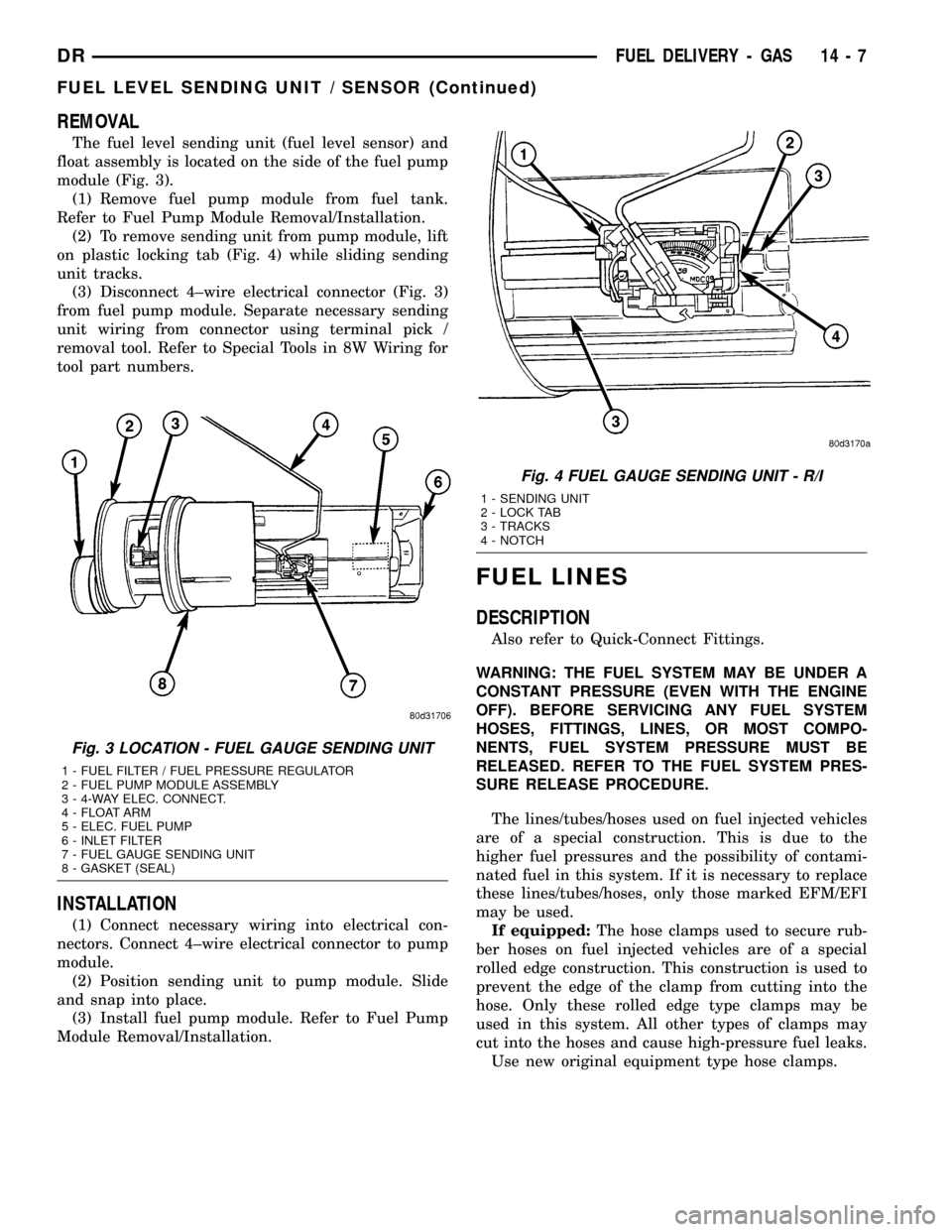
The fuel level sending unit (fuel level sensor) and
float assembly is located on the side of the fuel pump
module (Fig. 3).
(1) Remove fuel pump module from fuel tank.
Refer to Fuel Pump Module Removal/Installation.
(2) To remove sending unit from pump module, lift
on plastic locking tab (Fig. 4) while sliding sending
unit tracks.
(3) Disconnect 4±wire electrical connector (Fig. 3)
from fuel pump module. Separate necessary sending
unit wiring from connector using terminal pick /
removal tool. Refer to Special Tools in 8W Wiring for
tool part numbers.
INSTALLATION
(1) Connect necessary wiring into electrical con-
nectors. Connect 4±wire electrical connector to pump
module.
(2) Position sending unit to pump module. Slide
and snap into place.
(3) Install fuel pump module. Refer to Fuel Pump
Module Removal/Installation.
FUEL LINES
DESCRIPTION
Also refer to Quick-Connect Fittings.
WARNING: THE FUEL SYSTEM MAY BE UNDER A
CONSTANT PRESSURE (EVEN WITH THE ENGINE
OFF). BEFORE SERVICING ANY FUEL SYSTEM
HOSES, FITTINGS, LINES, OR MOST COMPO-
NENTS, FUEL SYSTEM PRESSURE MUST BE
RELEASED. REFER TO THE FUEL SYSTEM PRES-
SURE RELEASE PROCEDURE.
The lines/tubes/hoses used on fuel injected vehicles
are of a special construction. This is due to the
higher fuel pressures and the possibility of contami-
nated fuel in this system. If it is necessary to replace
these lines/tubes/hoses, only those marked EFM/EFI
may be used.
If equipped:The hose clamps used to secure rub-
ber hoses on fuel injected vehicles are of a special
rolled edge construction. This construction is used to
prevent the edge of the clamp from cutting into the
hose. Only these rolled edge type clamps may be
used in this system. All other types of clamps may
cut into the hoses and cause high-pressure fuel leaks.
Use new original equipment type hose clamps.
Fig. 3 LOCATION - FUEL GAUGE SENDING UNIT
1 - FUEL FILTER / FUEL PRESSURE REGULATOR
2 - FUEL PUMP MODULE ASSEMBLY
3 - 4-WAY ELEC. CONNECT.
4 - FLOAT ARM
5 - ELEC. FUEL PUMP
6 - INLET FILTER
7 - FUEL GAUGE SENDING UNIT
8 - GASKET (SEAL)
Fig. 4 FUEL GAUGE SENDING UNIT - R/I
1 - SENDING UNIT
2 - LOCK TAB
3 - TRACKS
4 - NOTCH
DRFUEL DELIVERY - GAS 14 - 7
FUEL LEVEL SENDING UNIT / SENSOR (Continued)