1998 DODGE RAM 1500 remove seats
[x] Cancel search: remove seatsPage 1495 of 2627
(6) Remove the wooden dowel rods and rubber
bands from the tappets.
(7) Lubricate the push rods with engine oil and
install in their original location.Verify that they
are seated in the tappets.
(8) Lubricate the valve tips with engine oil and
install the crossheads in their original locations.
(9) Lubricate the crossheads and push rod sockets
with engine oil and install the rocker arms and ped-
estals in their original locations. Tighten bolts to 36
N´m (27 ft. lbs.) torque.
(10)Verify valve lash adjustment (Refer to 9 -
ENGINE/CYLINDER HEAD/INTAKE/EXHAUST
VALVES & SEATS - STANDARD PROCEDURE).
(11) Install the cylinder head cover and reusable
gasket (Refer to 9 - ENGINE/CYLINDER HEAD/
CYLINDER HEAD COVER(S) - INSTALLATION).
(12) Install gear housing cover (Refer to 9 -
ENGINE/VALVE TIMING/GEAR HOUSING COVER
- INSTALLATION). Install front crankshaft dust
seal.
(13) Install the crankshaft damper with the speed
indicator ring (Refer to 9 - ENGINE/ENGINE
BLOCK/VIBRATION DAMPER - INSTALLATION).
(14) Install the fan support/hub assembly Refer to
(Refer to 7 - COOLING/ENGINE/RADIATOR FAN -
INSTALLATION).
(15) Install the power steering pump.
(16) Install accessory drive belt tensioner. Torque
bolt to 43 Nm (32 ft. lbs.).
(17) Install the accessory drive belt (Refer to 7 -
COOLING/ACCESSORY DRIVE/DRIVE BELTS -
INSTALLATION).
(18) Install the charge air cooler (with a/c con-
denser and auxiliary transmission oil cooler, if
equipped) and tighten the mounting bolts to 2 N´m
(17 in. lbs.) torque.
(19) Connect charge air cooler inlet and outlet
pipes. Tighten clamps to 11 N´m (95 in. lbs.) torque.
(20) Install the radiator upper support panel.
(21) Close radiator petcock and lower the radiator
into the engine compartment. Tighten the mounting
bolts to 11 N´m (95 in. lbs.) torque.
(22) Raise vehicle on hoist.
(23) Connect radiator lower hose and install
clamp.
(24) Connect transmission auxiliary oil cooler lines
(if equipped).
(25) Lower vehicle.
(26) Install the fan shroud and tighten the mount-
ing screws to 6 N´m (50 in. lbs.) torque.
(27) Install the electronically controlled viscous
fan/drive assembly. Connect harness connector.(Refer
to 7 - COOLING/ENGINE/RADIATOR FAN -
INSTALLATION).(28) Install the coolant recovery and windshield
washer fluid reservoirs to the fan shroud.
(29) Connect the coolant recovery hose to the radi-
ator filler neck.
(30) Add engine coolant (Refer to 7 - COOLING -
STANDARD PROCEDURE).
(31) Charge A/C system with refrigerant (if A/C
equipped) (Refer to 24 - HEATING & AIR CONDI-
TIONING/PLUMBING - STANDARD PROCEDURE).
(32) Connect the battery negative cables.
(33) Start engine and check for engine oil and cool-
ant leaks.
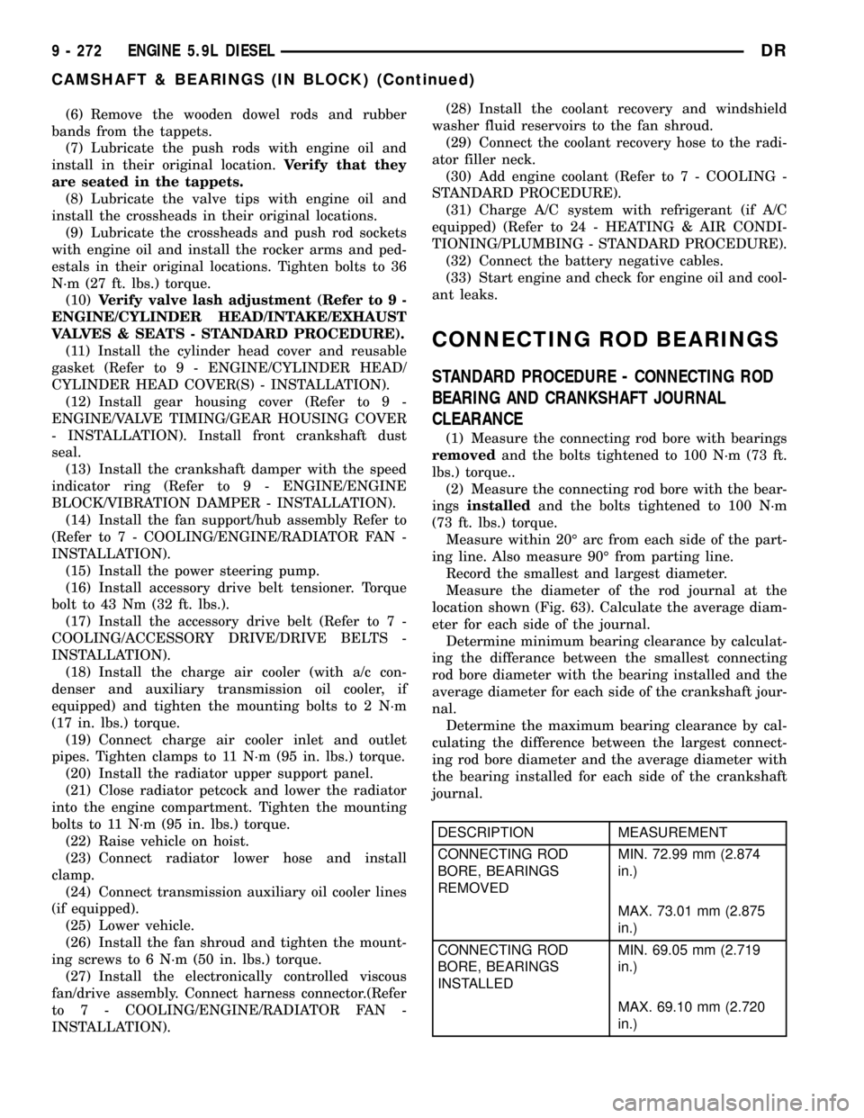
CONNECTING ROD BEARINGS
STANDARD PROCEDURE - CONNECTING ROD
BEARING AND CRANKSHAFT JOURNAL
CLEARANCE
(1) Measure the connecting rod bore with bearings
removedand the bolts tightened to 100 N´m (73 ft.
lbs.) torque..
(2) Measure the connecting rod bore with the bear-
ingsinstalledand the bolts tightened to 100 N´m
(73 ft. lbs.) torque.
Measure within 20É arc from each side of the part-
ing line. Also measure 90É from parting line.
Record the smallest and largest diameter.
Measure the diameter of the rod journal at the
location shown (Fig. 63). Calculate the average diam-
eter for each side of the journal.
Determine minimum bearing clearance by calculat-
ing the differance between the smallest connecting
rod bore diameter with the bearing installed and the
average diameter for each side of the crankshaft jour-
nal.
Determine the maximum bearing clearance by cal-
culating the difference between the largest connect-
ing rod bore diameter and the average diameter with
the bearing installed for each side of the crankshaft
journal.
DESCRIPTION MEASUREMENT
CONNECTING ROD
BORE, BEARINGS
REMOVEDMIN. 72.99 mm (2.874
in.)
MAX. 73.01 mm (2.875
in.)
CONNECTING ROD
BORE, BEARINGS
INSTALLEDMIN. 69.05 mm (2.719
in.)
MAX. 69.10 mm (2.720
in.)
9 - 272 ENGINE 5.9L DIESELDR
CAMSHAFT & BEARINGS (IN BLOCK) (Continued)
Page 1681 of 2627
NOTE: Tighten the slide hammer adapter 8990 into
the seal using wrenches, in order to make a tight fit
to pull the seal out. If this is not performed the seal
may tear on the removal making it difficult to
remove.
(12) Remove oil seal from the housing with a spe-
cial tool 8990 with slide hammer C-3752. (Fig. 5).
INSTALLATION
INSTALLATION - GAS ENGINE
NOTE: Generous amounts of the high temperature
grease from the seal kit should be applied to areas
between the pitman shaft bearing and oil seals and
also between the dust seals and snap ring.
(1) Coat the oil seal and washer withhigh temp
grease.
NOTE: Install the oil seal with the lip facing inward.
Flat side of the oil seal should be against the
washer.
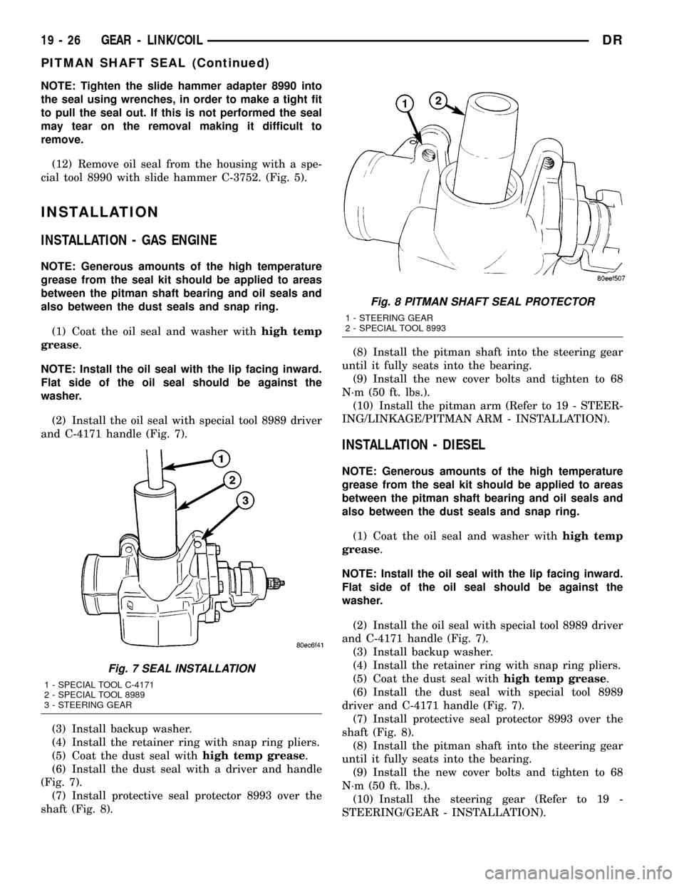
(2) Install the oil seal with special tool 8989 driver
and C-4171 handle (Fig. 7).
(3) Install backup washer.
(4) Install the retainer ring with snap ring pliers.
(5) Coat the dust seal withhigh temp grease.
(6) Install the dust seal with a driver and handle
(Fig. 7).
(7) Install protective seal protector 8993 over the
shaft (Fig. 8).(8) Install the pitman shaft into the steering gear
until it fully seats into the bearing.
(9) Install the new cover bolts and tighten to 68
N´m (50 ft. lbs.).
(10) Install the pitman arm (Refer to 19 - STEER-
ING/LINKAGE/PITMAN ARM - INSTALLATION).
INSTALLATION - DIESEL
NOTE: Generous amounts of the high temperature
grease from the seal kit should be applied to areas
between the pitman shaft bearing and oil seals and
also between the dust seals and snap ring.
(1) Coat the oil seal and washer withhigh temp
grease.
NOTE: Install the oil seal with the lip facing inward.
Flat side of the oil seal should be against the
washer.
(2) Install the oil seal with special tool 8989 driver
and C-4171 handle (Fig. 7).
(3) Install backup washer.
(4) Install the retainer ring with snap ring pliers.
(5) Coat the dust seal withhigh temp grease.
(6) Install the dust seal with special tool 8989
driver and C-4171 handle (Fig. 7).
(7) Install protective seal protector 8993 over the
shaft (Fig. 8).
(8) Install the pitman shaft into the steering gear
until it fully seats into the bearing.
(9) Install the new cover bolts and tighten to 68
N´m (50 ft. lbs.).
(10) Install the steering gear (Refer to 19 -
STEERING/GEAR - INSTALLATION).
Fig. 7 SEAL INSTALLATION
1 - SPECIAL TOOL C-4171
2 - SPECIAL TOOL 8989
3 - STEERING GEAR
Fig. 8 PITMAN SHAFT SEAL PROTECTOR
1 - STEERING GEAR
2 - SPECIAL TOOL 8993
19 - 26 GEAR - LINK/COILDR
PITMAN SHAFT SEAL (Continued)
Page 1685 of 2627
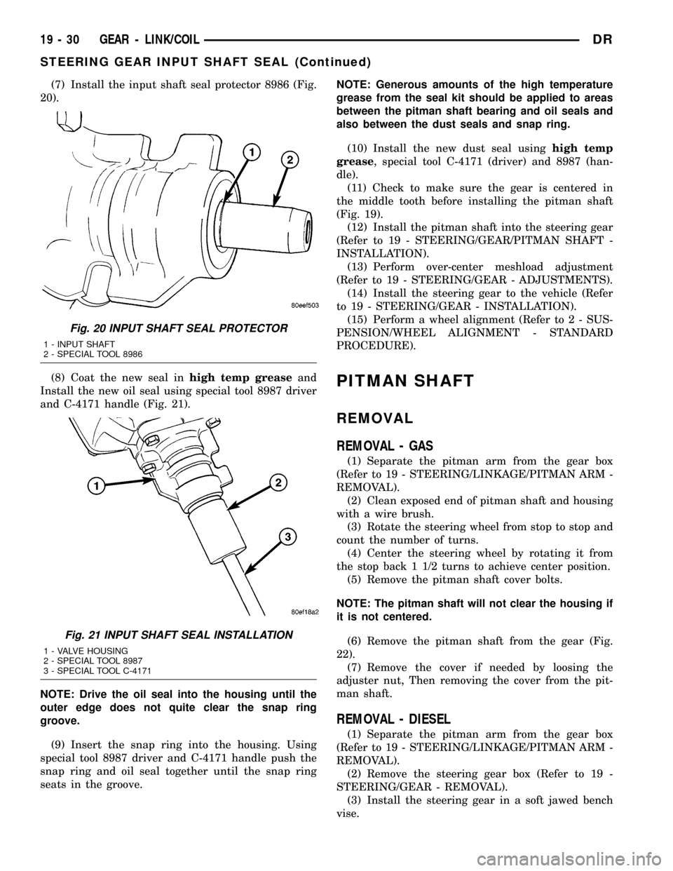
(7) Install the input shaft seal protector 8986 (Fig.
20).
(8) Coat the new seal inhigh temp greaseand
Install the new oil seal using special tool 8987 driver
and C-4171 handle (Fig. 21).
NOTE: Drive the oil seal into the housing until the
outer edge does not quite clear the snap ring
groove.
(9) Insert the snap ring into the housing. Using
special tool 8987 driver and C-4171 handle push the
snap ring and oil seal together until the snap ring
seats in the groove.NOTE: Generous amounts of the high temperature
grease from the seal kit should be applied to areas
between the pitman shaft bearing and oil seals and
also between the dust seals and snap ring.
(10) Install the new dust seal usinghigh temp
grease, special tool C-4171 (driver) and 8987 (han-
dle).
(11) Check to make sure the gear is centered in
the middle tooth before installing the pitman shaft
(Fig. 19).
(12) Install the pitman shaft into the steering gear
(Refer to 19 - STEERING/GEAR/PITMAN SHAFT -
INSTALLATION).
(13) Perform over-center meshload adjustment
(Refer to 19 - STEERING/GEAR - ADJUSTMENTS).
(14) Install the steering gear to the vehicle (Refer
to 19 - STEERING/GEAR - INSTALLATION).
(15) Perform a wheel alignment (Refer to 2 - SUS-
PENSION/WHEEL ALIGNMENT - STANDARD
PROCEDURE).
PITMAN SHAFT
REMOVAL
REMOVAL - GAS
(1) Separate the pitman arm from the gear box
(Refer to 19 - STEERING/LINKAGE/PITMAN ARM -
REMOVAL).
(2) Clean exposed end of pitman shaft and housing
with a wire brush.
(3) Rotate the steering wheel from stop to stop and
count the number of turns.
(4) Center the steering wheel by rotating it from
the stop back 1 1/2 turns to achieve center position.
(5) Remove the pitman shaft cover bolts.
NOTE: The pitman shaft will not clear the housing if
it is not centered.
(6) Remove the pitman shaft from the gear (Fig.
22).
(7) Remove the cover if needed by loosing the
adjuster nut, Then removing the cover from the pit-
man shaft.
REMOVAL - DIESEL
(1) Separate the pitman arm from the gear box
(Refer to 19 - STEERING/LINKAGE/PITMAN ARM -
REMOVAL).
(2) Remove the steering gear box (Refer to 19 -
STEERING/GEAR - REMOVAL).
(3) Install the steering gear in a soft jawed bench
vise.
Fig. 20 INPUT SHAFT SEAL PROTECTOR
1 - INPUT SHAFT
2 - SPECIAL TOOL 8986
Fig. 21 INPUT SHAFT SEAL INSTALLATION
1 - VALVE HOUSING
2 - SPECIAL TOOL 8987
3 - SPECIAL TOOL C-4171
19 - 30 GEAR - LINK/COILDR
STEERING GEAR INPUT SHAFT SEAL (Continued)
Page 1686 of 2627
(4) Clean exposed end of pitman shaft and housing
with a wire brush.
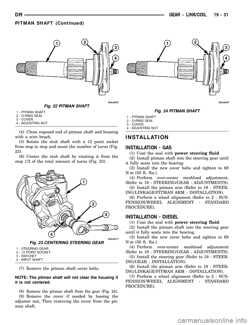
(5) Rotate the stub shaft with a 12 point socket
from stop to stop and count the number of turns (Fig.
23).
(6) Center the stub shaft by rotating it from the
stop 1/2 of the total amount of turns (Fig. 23).
(7) Remove the pitman shaft cover bolts.
NOTE: The pitman shaft will not clear the housing if
it is not centered.
(8)
Remove the pitman shaft from the gear (Fig. 24).
(9) Remove the cover if needed by loosing the
adjuster nut, Then removing the cover from the pit-
man shaft.
INSTALLATION
INSTALLATION - GAS
(1) Coat the seal withpower steering fluid.
(2) Install pitman shaft into the steering gear until
it fully seats into the bearing.
(3) Install the new cover bolts and tighten to 68
N´m (50 ft. lbs.).
(4) Perform over-center meshload adjustment,
(Refer to 19 - STEERING/GEAR - ADJUSTMENTS).
(5) Install the pitman arm (Refer to 19 - STEER-
ING/LINKAGE/PITMAN ARM - INSTALLATION).
(6) Perform a wheel alignment (Refer to 2 - SUS-
PENSION/WHEEL ALIGNMENT - STANDARD
PROCEDURE).
INSTALLATION - DIESEL
(1) Coat the seal withpower steering fluid.
(2) Install the pitman shaft into the steering gear
until it fully seats into the bearing.
(3) Install the new cover bolts and tighten to 68
N´m (50 ft. lbs.).
(4) Perform over-center meshload adjustment
(Refer to 19 - STEERING/GEAR - ADJUSTMENTS).
(5) Install the steering gear (Refer to 19 - STEER-
ING/GEAR - INSTALLATION).
(6) Install the pitman arm (Refer to 19 - STEER-
ING/LINKAGE/PITMAN ARM - INSTALLATION).
(7) Perform a wheel alignment (Refer to 2 - SUS-
PENSION/WHEEL ALIGNMENT - STANDARD
PROCEDURE).
Fig. 22 PITMAN SHAFT
1 - PITMAN SHAFT
2 - O-RING SEAL
3 - COVER
4 - ADJUSTING NUT
Fig. 23 CENTERING STEERING GEAR
1 - STEERING GEAR
2 - 12 POINT SOCKET
3 - RATCHET
4 - INPUT SHAFT
Fig. 24 PITMAN SHAFT
1 - PITMAN SHAFT
2 - O-RING SEAL
3 - COVER
4 - ADJUSTING NUT
DRGEAR - LINK/COIL 19 - 31
PITMAN SHAFT (Continued)
Page 2296 of 2627
BODY
TABLE OF CONTENTS
page page
BODY
WARNING
SAFETY PRECAUTIONS AND WARNINGS . . . 1
DIAGNOSIS AND TESTING
DIAGNOSIS AND TESTING - WATER LEAKS . 1
DIAGNOSIS AND TESTING - WIND NOISE . . . 2
STANDARD PROCEDURE
STANDARD PROCEDURE - BODY
LUBRICATION.........................3
STANDARD PROCEDURE - HEAT STAKING . . 3
STANDARD PROCEDURE - PLASTIC BODY
PANEL REPAIR........................3
STANDARD PROCEDURE - BUZZ, SQUEAK
& RATTLE...........................11
SPECIFICATIONS - TORQUE..............12SPECIAL TOOLS
BODY..............................14
TAILGATE..............................15
DOOR - FRONT.........................18
DOORS - REAR.........................28
EXTERIOR.............................36
HOOD.................................46
INSTRUMENT PANEL.....................49
INTERIOR..............................62
PAINT.................................73
SEATS................................75
STATIONARY GLASS.....................86
WEATHERSTRIP/SEALS...................91
BODY STRUCTURE......................95
BODY
WARNING
SAFETY PRECAUTIONS AND WARNINGS
WARNING: USE AN OSHA APPROVED BREATHING
FILTER WHEN SPRAYING PAINT OR SOLVENTS IN
A CONFINED AREA. PERSONAL INJURY CAN
RESULT.
²AVOID PROLONGED SKIN CONTACT WITH
PETROLEUM OR ALCOHOL ± BASED CLEANING
SOLVENTS. PERSONAL INJURY CAN RESULT.
²DO NOT STAND UNDER A HOISTED VEHICLE
THAT IS NOT PROPERLY SUPPORTED ON SAFETY
STANDS. PERSONAL INJURY CAN RESULT.
CAUTION: When holes must be drilled or punched
in an inner body panel, verify depth of space to the
outer body panel, electrical wiring, or other compo-
nents. Damage to vehicle can result.
²Do not weld exterior panels unless combustible
material on the interior of vehicle is removed from
the repair area. Fire or hazardous conditions, can
result.
²Always have a fire extinguisher ready for use
when welding.
²Disconnect the negative (-) cable clamp from
the battery when servicing electrical components
that are live when the ignition is OFF. Damage to
electrical system can result.²Do not use abrasive chemicals or compounds
on painted surfaces. Damage to finish can result.
²Do not use harsh alkaline based cleaning sol-
vents on painted or upholstered surfaces. Damage
to finish or color can result.
²Do not hammer or pound on plastic trim panel
when servicing interior trim. Plastic panels can
break.
DIAGNOSIS AND TESTING
DIAGNOSIS AND TESTING - WATER LEAKS
Water leaks can be caused by poor sealing,
improper body component alignment, body seam
porosity, missing plugs, or blocked drain holes. Cen-
trifugal and gravitational force can cause water to
drip from a location away from the actual leak point,
making leak detection difficult. All body sealing
points should be water tight in normal wet-driving
conditions. Water flowing downward from the front of
the vehicle should not enter the passenger or luggage
compartment. Moving sealing surfaces will not
always seal water tight under all conditions. At
times, side glass or door seals will allow water to
enter the passenger compartment during high pres-
sure washing or hard driving rain (severe) condi-
tions. Overcompensating on door or glass
adjustments to stop a water leak that occurs under
severe conditions can cause premature seal wear and
excessive closing or latching effort. After completing
a repair, water test vehicle to verify leak has stopped
before returning vehicle to use.
DRBODY 23 - 1
Page 2339 of 2627
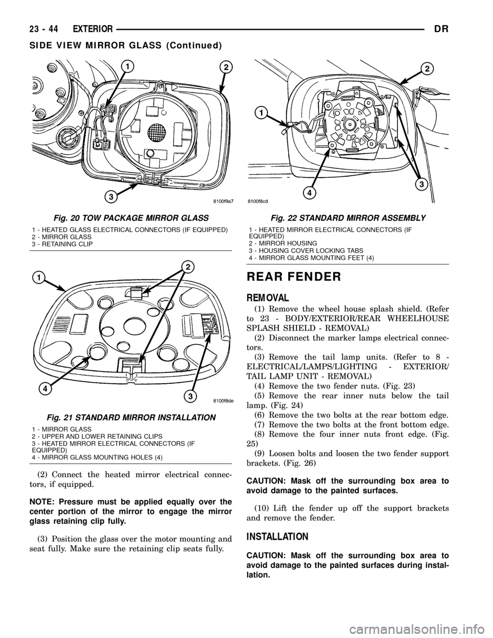
(2) Connect the heated mirror electrical connec-
tors, if equipped.
NOTE: Pressure must be applied equally over the
center portion of the mirror to engage the mirror
glass retaining clip fully.
(3) Position the glass over the motor mounting and
seat fully. Make sure the retaining clip seats fully.
REAR FENDER
REMOVAL
(1) Remove the wheel house splash shield. (Refer
to 23 - BODY/EXTERIOR/REAR WHEELHOUSE
SPLASH SHIELD - REMOVAL)
(2) Disconnect the marker lamps electrical connec-
tors.
(3) Remove the tail lamp units. (Refer to 8 -
ELECTRICAL/LAMPS/LIGHTING - EXTERIOR/
TAIL LAMP UNIT - REMOVAL)
(4) Remove the two fender nuts. (Fig. 23)
(5) Remove the rear inner nuts below the tail
lamp. (Fig. 24)
(6) Remove the two bolts at the rear bottom edge.
(7) Remove the two bolts at the front bottom edge.
(8) Remove the four inner nuts front edge. (Fig.
25)
(9) Loosen bolts and loosen the two fender support
brackets. (Fig. 26)
CAUTION: Mask off the surrounding box area to
avoid damage to the painted surfaces.
(10) Lift the fender up off the support brackets
and remove the fender.
INSTALLATION
CAUTION: Mask off the surrounding box area to
avoid damage to the painted surfaces during instal-
lation.
Fig. 20 TOW PACKAGE MIRROR GLASS
1 - HEATED GLASS ELECTRICAL CONNECTORS (IF EQUIPPED)
2 - MIRROR GLASS
3 - RETAINING CLIP
Fig. 21 STANDARD MIRROR INSTALLATION
1 - MIRROR GLASS
2 - UPPER AND LOWER RETAINING CLIPS
3 - HEATED MIRROR ELECTRICAL CONNECTORS (IF
EQUIPPED)
4 - MIRROR GLASS MOUNTING HOLES (4)
Fig. 22 STANDARD MIRROR ASSEMBLY
1 - HEATED MIRROR ELECTRICAL CONNECTORS (IF
EQUIPPED)
2 - MIRROR HOUSING
3 - HOUSING COVER LOCKING TABS
4 - MIRROR GLASS MOUNTING FEET (4)
23 - 44 EXTERIORDR
SIDE VIEW MIRROR GLASS (Continued)
Page 2360 of 2627
CARPETS AND FLOOR MATS
REMOVAL
(1) Remove the front seats. (Refer to 23 - BODY/
SEATS/SEAT - FRONT - REMOVAL)
(2) Remove the rear seats, if equipped. (Refer to 23
- BODY/SEATS/SEAT - REAR - REMOVAL)(3) Remove the floor console, if equipped. (Refer to
23 - BODY/INTERIOR/FLOOR CONSOLE -
REMOVAL)
(4) Remove the lower b-pillar trim. (Refer to 23 -
BODY/INTERIOR/B-PILLAR LOWER TRIM -
REMOVAL)
(5) On quad cab models, remove the lower seat
belt anchor next to the b-pillar.
(6) Using a trim stick C-4755 or equivalent,
remove the rear cup holder, if equipped.
(7) Remove the jack assembly.
(8) Remove the carpet.
INSTALLATION
(1) Install the carpet.
(2) Install the jack assembly.
(3) Install the rear cup holder, if equipped.
(4) Install the lower b-pillar trim. (Refer to 23 -
BODY/INTERIOR/B-PILLAR LOWER TRIM -
INSTALLATION)
(5) On quad cab models, install the lower seatbelt
anchor bolt next to the b-pillar and tighten to 40 N´m
(30 ft. lbs.).
(6) Install the floor console, if equipped. (Refer to
23 - BODY/INTERIOR/FLOOR CONSOLE - INSTAL-
LATION)
(7) Install the rear seats, if equipped. (Refer to 23
- BODY/SEATS/SEAT - REAR - INSTALLATION)
(8) Install the front seats. (Refer to 23 - BODY/
SEATS/SEAT - FRONT - INSTALLATION)
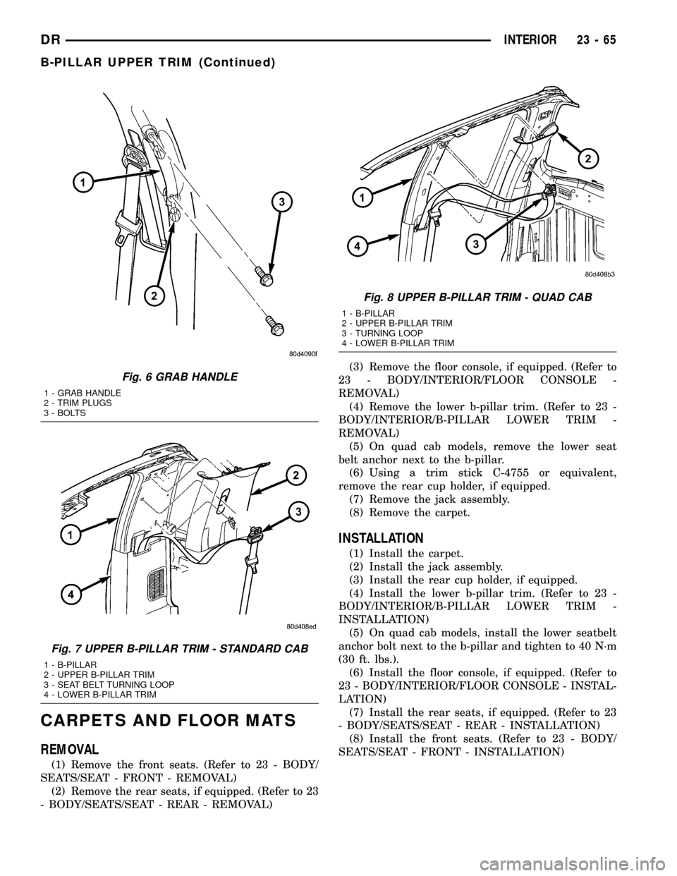
Fig. 6 GRAB HANDLE
1 - GRAB HANDLE
2 - TRIM PLUGS
3 - BOLTS
Fig. 7 UPPER B-PILLAR TRIM - STANDARD CAB
1 - B-PILLAR
2 - UPPER B-PILLAR TRIM
3 - SEAT BELT TURNING LOOP
4 - LOWER B-PILLAR TRIM
Fig. 8 UPPER B-PILLAR TRIM - QUAD CAB
1 - B-PILLAR
2 - UPPER B-PILLAR TRIM
3 - TURNING LOOP
4 - LOWER B-PILLAR TRIM
DRINTERIOR 23 - 65
B-PILLAR UPPER TRIM (Continued)
Page 2361 of 2627
COAT HOOK
REMOVAL
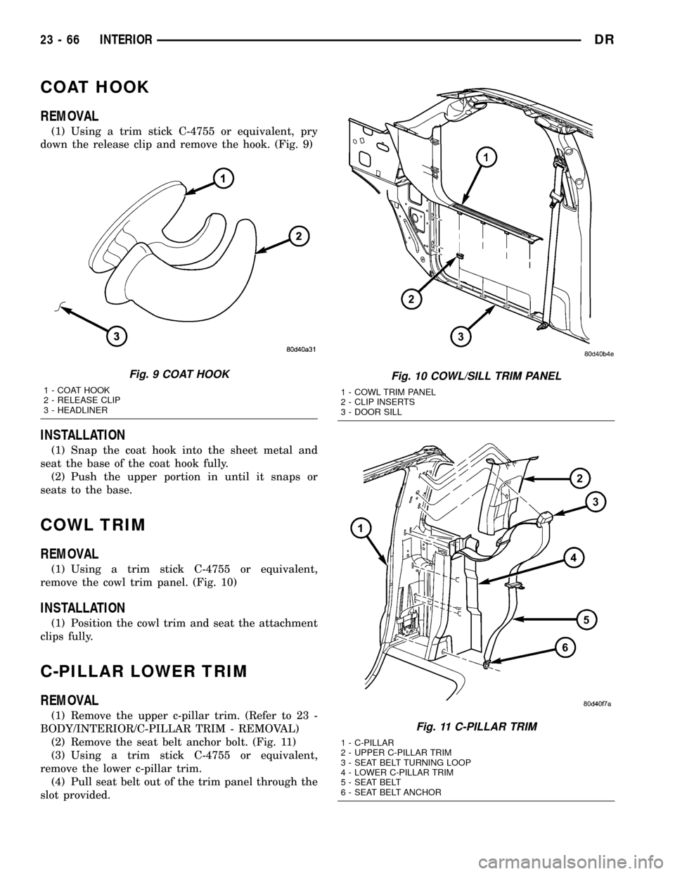
(1) Using a trim stick C-4755 or equivalent, pry
down the release clip and remove the hook. (Fig. 9)
INSTALLATION
(1) Snap the coat hook into the sheet metal and
seat the base of the coat hook fully.
(2) Push the upper portion in until it snaps or
seats to the base.
COWL TRIM
REMOVAL
(1) Using a trim stick C-4755 or equivalent,
remove the cowl trim panel. (Fig. 10)
INSTALLATION
(1) Position the cowl trim and seat the attachment
clips fully.
C-PILLAR LOWER TRIM
REMOVAL
(1) Remove the upper c-pillar trim. (Refer to 23 -
BODY/INTERIOR/C-PILLAR TRIM - REMOVAL)
(2) Remove the seat belt anchor bolt. (Fig. 11)
(3) Using a trim stick C-4755 or equivalent,
remove the lower c-pillar trim.
(4) Pull seat belt out of the trim panel through the
slot provided.
Fig. 9 COAT HOOK
1 - COAT HOOK
2 - RELEASE CLIP
3 - HEADLINER
Fig. 10 COWL/SILL TRIM PANEL
1 - COWL TRIM PANEL
2 - CLIP INSERTS
3 - DOOR SILL
Fig. 11 C-PILLAR TRIM
1 - C-PILLAR
2 - UPPER C-PILLAR TRIM
3 - SEAT BELT TURNING LOOP
4 - LOWER C-PILLAR TRIM
5 - SEAT BELT
6 - SEAT BELT ANCHOR
23 - 66 INTERIORDR