1998 DODGE RAM 1500 oil
[x] Cancel search: oilPage 1685 of 2627
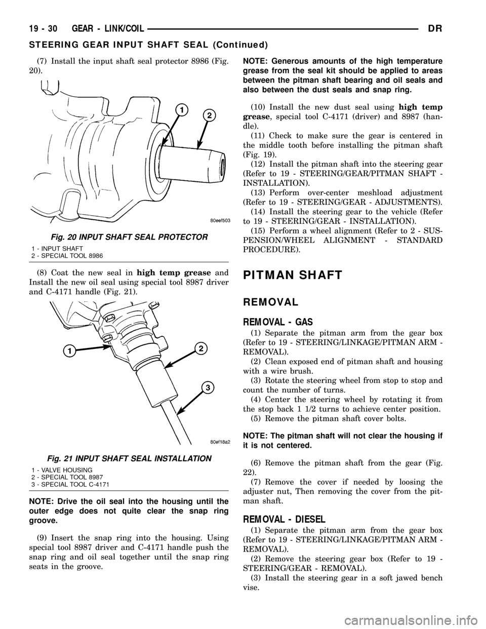
(7) Install the input shaft seal protector 8986 (Fig.
20).
(8) Coat the new seal inhigh temp greaseand
Install the new oil seal using special tool 8987 driver
and C-4171 handle (Fig. 21).
NOTE: Drive the oil seal into the housing until the
outer edge does not quite clear the snap ring
groove.
(9) Insert the snap ring into the housing. Using
special tool 8987 driver and C-4171 handle push the
snap ring and oil seal together until the snap ring
seats in the groove.NOTE: Generous amounts of the high temperature
grease from the seal kit should be applied to areas
between the pitman shaft bearing and oil seals and
also between the dust seals and snap ring.
(10) Install the new dust seal usinghigh temp
grease, special tool C-4171 (driver) and 8987 (han-
dle).
(11) Check to make sure the gear is centered in
the middle tooth before installing the pitman shaft
(Fig. 19).
(12) Install the pitman shaft into the steering gear
(Refer to 19 - STEERING/GEAR/PITMAN SHAFT -
INSTALLATION).
(13) Perform over-center meshload adjustment
(Refer to 19 - STEERING/GEAR - ADJUSTMENTS).
(14) Install the steering gear to the vehicle (Refer
to 19 - STEERING/GEAR - INSTALLATION).
(15) Perform a wheel alignment (Refer to 2 - SUS-
PENSION/WHEEL ALIGNMENT - STANDARD
PROCEDURE).
PITMAN SHAFT
REMOVAL
REMOVAL - GAS
(1) Separate the pitman arm from the gear box
(Refer to 19 - STEERING/LINKAGE/PITMAN ARM -
REMOVAL).
(2) Clean exposed end of pitman shaft and housing
with a wire brush.
(3) Rotate the steering wheel from stop to stop and
count the number of turns.
(4) Center the steering wheel by rotating it from
the stop back 1 1/2 turns to achieve center position.
(5) Remove the pitman shaft cover bolts.
NOTE: The pitman shaft will not clear the housing if
it is not centered.
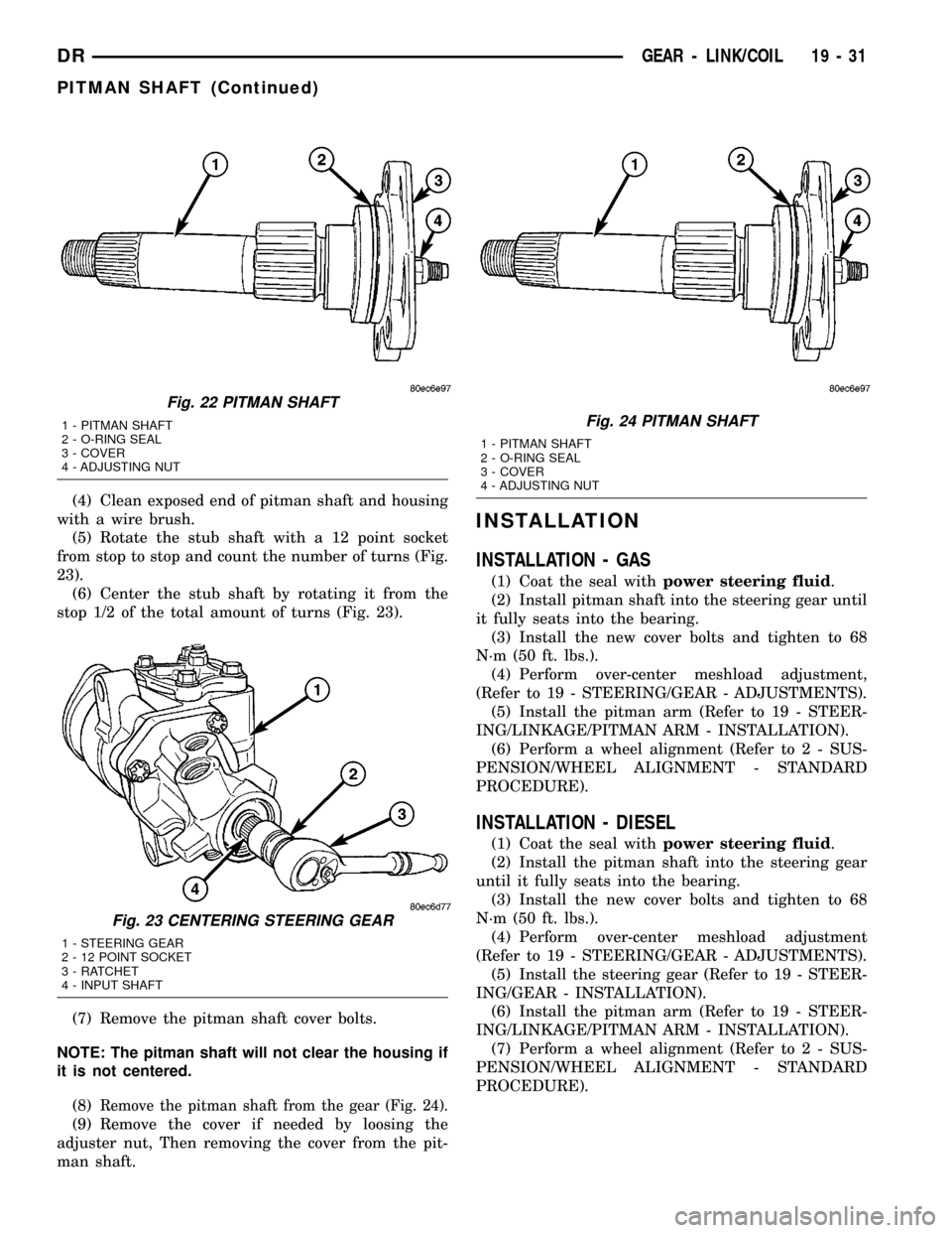
(6) Remove the pitman shaft from the gear (Fig.
22).
(7) Remove the cover if needed by loosing the
adjuster nut, Then removing the cover from the pit-
man shaft.
REMOVAL - DIESEL
(1) Separate the pitman arm from the gear box
(Refer to 19 - STEERING/LINKAGE/PITMAN ARM -
REMOVAL).
(2) Remove the steering gear box (Refer to 19 -
STEERING/GEAR - REMOVAL).
(3) Install the steering gear in a soft jawed bench
vise.
Fig. 20 INPUT SHAFT SEAL PROTECTOR
1 - INPUT SHAFT
2 - SPECIAL TOOL 8986
Fig. 21 INPUT SHAFT SEAL INSTALLATION
1 - VALVE HOUSING
2 - SPECIAL TOOL 8987
3 - SPECIAL TOOL C-4171
19 - 30 GEAR - LINK/COILDR
STEERING GEAR INPUT SHAFT SEAL (Continued)
Page 1686 of 2627
(4) Clean exposed end of pitman shaft and housing
with a wire brush.
(5) Rotate the stub shaft with a 12 point socket
from stop to stop and count the number of turns (Fig.
23).
(6) Center the stub shaft by rotating it from the
stop 1/2 of the total amount of turns (Fig. 23).
(7) Remove the pitman shaft cover bolts.
NOTE: The pitman shaft will not clear the housing if
it is not centered.
(8)
Remove the pitman shaft from the gear (Fig. 24).
(9) Remove the cover if needed by loosing the
adjuster nut, Then removing the cover from the pit-
man shaft.
INSTALLATION
INSTALLATION - GAS
(1) Coat the seal withpower steering fluid.
(2) Install pitman shaft into the steering gear until
it fully seats into the bearing.
(3) Install the new cover bolts and tighten to 68
N´m (50 ft. lbs.).
(4) Perform over-center meshload adjustment,
(Refer to 19 - STEERING/GEAR - ADJUSTMENTS).
(5) Install the pitman arm (Refer to 19 - STEER-
ING/LINKAGE/PITMAN ARM - INSTALLATION).
(6) Perform a wheel alignment (Refer to 2 - SUS-
PENSION/WHEEL ALIGNMENT - STANDARD
PROCEDURE).
INSTALLATION - DIESEL
(1) Coat the seal withpower steering fluid.
(2) Install the pitman shaft into the steering gear
until it fully seats into the bearing.
(3) Install the new cover bolts and tighten to 68
N´m (50 ft. lbs.).
(4) Perform over-center meshload adjustment
(Refer to 19 - STEERING/GEAR - ADJUSTMENTS).
(5) Install the steering gear (Refer to 19 - STEER-
ING/GEAR - INSTALLATION).
(6) Install the pitman arm (Refer to 19 - STEER-
ING/LINKAGE/PITMAN ARM - INSTALLATION).
(7) Perform a wheel alignment (Refer to 2 - SUS-
PENSION/WHEEL ALIGNMENT - STANDARD
PROCEDURE).
Fig. 22 PITMAN SHAFT
1 - PITMAN SHAFT
2 - O-RING SEAL
3 - COVER
4 - ADJUSTING NUT
Fig. 23 CENTERING STEERING GEAR
1 - STEERING GEAR
2 - 12 POINT SOCKET
3 - RATCHET
4 - INPUT SHAFT
Fig. 24 PITMAN SHAFT
1 - PITMAN SHAFT
2 - O-RING SEAL
3 - COVER
4 - ADJUSTING NUT
DRGEAR - LINK/COIL 19 - 31
PITMAN SHAFT (Continued)
Page 1689 of 2627

LINKAGE - LINK/COIL
TABLE OF CONTENTS
page page
LINKAGE - LINK/COIL
DESCRIPTION.........................34
STANDARD PROCEDURE - LUBRICATION....34
SPECIFICATIONS
TORQUE CHART......................35
SPECIAL TOOLS
STEERING LINKAGE...................35
DAMPER
REMOVAL.............................36
INSTALLATION.........................36
DRAG LINK
REMOVAL.............................36INSTALLATION.........................36
PITMAN ARM
REMOVAL.............................36
INSTALLATION.........................37
TIE ROD END
REMOVAL.............................37
INSTALLATION.........................37
TRACK BAR
REMOVAL.............................38
INSTALLATION.........................38
LINKAGE - LINK/COIL
DESCRIPTION
The steering linkage is comprised of a tie rod end, tie
rod, drag link, steering damper and pitman arm (Fig. 1).
CAUTION: If any steering components are replaced
or serviced an alignment must be performed.
NOTE: To avoid damaging ball stud seals, use
Puller C-3894±A or an appropriate puller to remove
tie rod ends (Fig. 2).
STANDARD PROCEDURE - LUBRICATION
Periodic lubrication of the steering system compo-
nents is required. Refer to Lubrication And Mainte-
nance for the recommended maintenance schedule.
The following components must be lubricated:
²Tie rod
²Tie rod end
²Drag link
Fig. 1 LINK/COIL FRONT SUSPENSION
1 - STABILIZER BAR
2 - PITMAN ARM
3 - STEERING GEAR
4 - STABILIZER LINK
5 - TIE ROD ENDS
6 - LOWER SUSPENSION ARMS
7 - DRAG LINK
8 - TRACK BAR
9 - DAMPER
10 - UPPER SUSPENSION ARM
Fig. 2 Ball Stud Puller
1 - CLAMP
2 - ADJUSTMENT SLEEVE
3 - PULLER TOOL C-3894±A
4 - SEAL
5 - TIE-ROD END
19 - 34 LINKAGE - LINK/COILDR
Page 1690 of 2627
SPECIFICATIONS
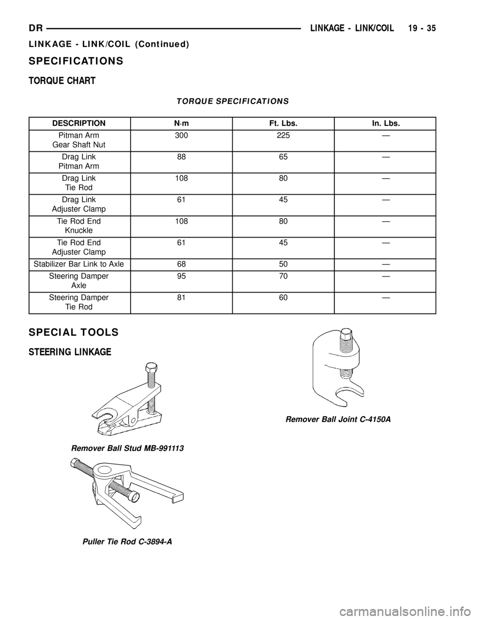
TORQUE CHART
TORQUE SPECIFICATIONS
DESCRIPTION N´m Ft. Lbs. In. Lbs.
Pitman Arm
Gear Shaft Nut300 225 Ð
Drag Link
Pitman Arm88 65 Ð
Drag Link
Tie Rod108 80 Ð
Drag Link
Adjuster Clamp61 45 Ð
Tie Rod End
Knuckle108 80 Ð
Tie Rod End
Adjuster Clamp61 45 Ð
Stabilizer Bar Link to Axle 68 50 Ð
Steering Damper
Axle95 70 Ð
Steering Damper
Tie Rod81 60 Ð
SPECIAL TOOLS
STEERING LINKAGE
Remover Ball Stud MB-991113
Puller Tie Rod C-3894-A
Remover Ball Joint C-4150A
DRLINKAGE - LINK/COIL 19 - 35
LINKAGE - LINK/COIL (Continued)
Page 1691 of 2627
DAMPER
REMOVAL
(1) Remove the steering damper mounting nuts
and bolts.
(2) Slide the damper from the isolation bushing.
(3) Remove the damper.
INSTALLATION
(1) Install the steering damper on the axle and iso-
lation bushing. Tighten nut to 95 N´m (75 ft. lbs.).
(2) Install the steering damper on the tie rod.
Tighten nut to 81 N´m (60 ft. lbs.).
DRAG LINK
REMOVAL
(1) Remove the draglink nut from the pitman arm
side.
(2)
Remove the drag link nut from the knuckle side.
(3) Remove the drag link from the right knuckle
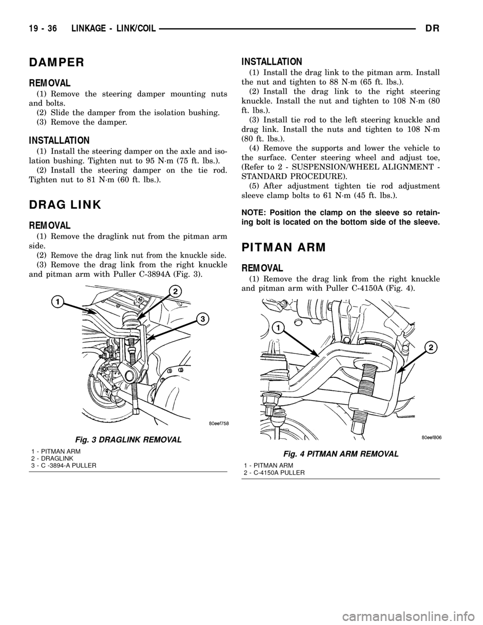
and pitman arm with Puller C-3894A (Fig. 3).
INSTALLATION
(1) Install the drag link to the pitman arm. Install
the nut and tighten to 88 N´m (65 ft. lbs.).
(2) Install the drag link to the right steering
knuckle. Install the nut and tighten to 108 N´m (80
ft. lbs.).
(3) Install tie rod to the left steering knuckle and
drag link. Install the nuts and tighten to 108 N´m
(80 ft. lbs.).
(4) Remove the supports and lower the vehicle to
the surface. Center steering wheel and adjust toe,
(Refer to 2 - SUSPENSION/WHEEL ALIGNMENT -
STANDARD PROCEDURE).
(5) After adjustment tighten tie rod adjustment
sleeve clamp bolts to 61 N´m (45 ft. lbs.).
NOTE: Position the clamp on the sleeve so retain-
ing bolt is located on the bottom side of the sleeve.
PITMAN ARM
REMOVAL
(1) Remove the drag link from the right knuckle
and pitman arm with Puller C-4150A (Fig. 4).
Fig. 3 DRAGLINK REMOVAL
1 - PITMAN ARM
2 - DRAGLINK
3 - C -3894-A PULLERFig. 4 PITMAN ARM REMOVAL
1 - PITMAN ARM
2 - C-4150A PULLER
19 - 36 LINKAGE - LINK/COILDR
Page 1692 of 2627
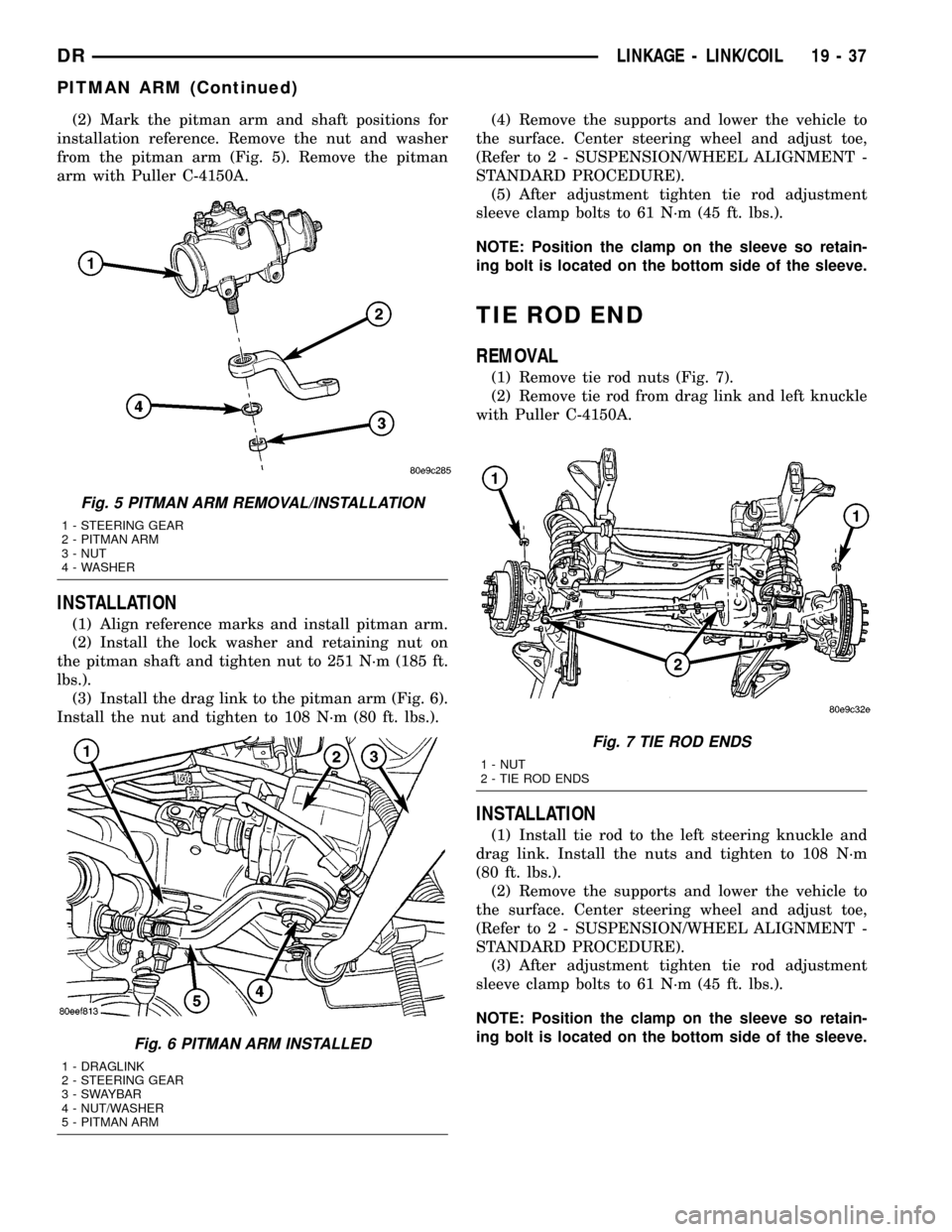
(2) Mark the pitman arm and shaft positions for
installation reference. Remove the nut and washer
from the pitman arm (Fig. 5). Remove the pitman
arm with Puller C-4150A.
INSTALLATION
(1) Align reference marks and install pitman arm.
(2) Install the lock washer and retaining nut on
the pitman shaft and tighten nut to 251 N´m (185 ft.
lbs.).
(3) Install the drag link to the pitman arm (Fig. 6).
Install the nut and tighten to 108 N´m (80 ft. lbs.).(4) Remove the supports and lower the vehicle to
the surface. Center steering wheel and adjust toe,
(Refer to 2 - SUSPENSION/WHEEL ALIGNMENT -
STANDARD PROCEDURE).
(5) After adjustment tighten tie rod adjustment
sleeve clamp bolts to 61 N´m (45 ft. lbs.).
NOTE: Position the clamp on the sleeve so retain-
ing bolt is located on the bottom side of the sleeve.
TIE ROD END
REMOVAL
(1) Remove tie rod nuts (Fig. 7).
(2) Remove tie rod from drag link and left knuckle
with Puller C-4150A.
INSTALLATION
(1) Install tie rod to the left steering knuckle and
drag link. Install the nuts and tighten to 108 N´m
(80 ft. lbs.).
(2) Remove the supports and lower the vehicle to
the surface. Center steering wheel and adjust toe,
(Refer to 2 - SUSPENSION/WHEEL ALIGNMENT -
STANDARD PROCEDURE).
(3) After adjustment tighten tie rod adjustment
sleeve clamp bolts to 61 N´m (45 ft. lbs.).
NOTE: Position the clamp on the sleeve so retain-
ing bolt is located on the bottom side of the sleeve.
Fig. 5 PITMAN ARM REMOVAL/INSTALLATION
1 - STEERING GEAR
2 - PITMAN ARM
3 - NUT
4 - WASHER
Fig. 6 PITMAN ARM INSTALLED
1 - DRAGLINK
2 - STEERING GEAR
3 - SWAYBAR
4 - NUT/WASHER
5 - PITMAN ARM
Fig. 7 TIE ROD ENDS
1 - NUT
2 - TIE ROD ENDS
DRLINKAGE - LINK/COIL 19 - 37
PITMAN ARM (Continued)
Page 1693 of 2627

TRACK BAR
REMOVAL
(1) Raise and support the axle.
(2) Remove the track bar bolts and nuts (Fig. 8).
(3) Remove the track bar (Fig. 8).
INSTALLATION
(1) Install the track bar.
(2) Install the new bolts and nuts. Tighten to 203
N´m (150 ft lbs.).
(3) Remove the supports under the axle and lower
the vehicle to the ground.
Fig. 8 TRACK BAR REMOVAL/INSTALLATION
1 - TRACK BAR
2 - BOLT
3 - NUT
19 - 38 LINKAGE - LINK/COILDR
Page 1694 of 2627

PUMP
TABLE OF CONTENTS
page page
PUMP
DESCRIPTION.........................39
OPERATION...........................40
DIAGNOSIS AND TESTING - PUMP LEAKAGE . 40
STANDARD PROCEDURE
STANDARD PROCEDURE - POWER
STEERING PUMP - INITIAL OPERATION....40
STANDARD PROCEDURE - FLUSHING
POWER STEERING SYSTEM............40
REMOVAL
REMOVAL - GAS......................41
REMOVAL - DIESEL...................41
INSTALLATION
INSTALLATION - GAS..................42
INSTALLATION - DIESEL................42
SPECIFICATIONS
TORQUE CHART......................42
FLUID
DESCRIPTION.........................43
STANDARD PROCEDURE - POWER
STEERING FLUID LEVEL CHECKING......43
FLUID COOLER
REMOVAL.............................43
INSTALLATION.........................43
HOSES - I.F.S.
REMOVAL
REMOVAL - RETURN HOSE - GEAR TO
COOLER............................44
REMOVAL - PRESSURE HOSE...........44
REMOVAL - RETURN HOSE - RESERVOIR
TO COOLER.........................44INSTALLATION
INSTALLATION - RETURN HOSE - GEAR TO
COOLER............................44
INSTALLATION - PRESSURE HOSE.......44
INSTALLATION - RETURN HOSE -
RESERVOIR TO COOLER...............44
HOSES - LINK/COIL
REMOVAL
REMOVAL - RETURN HOSE - GEAR TO
COOLER............................45
REMOVAL - PRESSURE HOSE...........45
REMOVAL - RETURN HOSE - RESERVOIR
TO COOLER.........................45
INSTALLATION
INSTALLATION - RETURN HOSE - GEAR TO
COOLER............................45
INSTALLATION - PRESSURE HOSE.......45
INSTALLATION - RETURN HOSE -
RESERVOIR TO COOLER...............45
POWER STEERING PRESSURE SWITCH
DESCRIPTION.........................46
OPERATION...........................46
REMOVAL - 3.7L & 5.7L..................46
INSTALLATION - 3.7L & 5.7L...............46
PULLEY
REMOVAL.............................47
INSTALLATION.........................47
RESERVOIR
REMOVAL.............................47
INSTALLATION.........................47
PUMP
DESCRIPTION
CAUTION: MOPARTATF+4 is to be used in the
power steering system. No other power steering or
automatic transmission fluid is to be used in the
system. Damage may result to the power steering
pump and system if any other fluid is used, and do
not overfill.The pump is connected to the steering gear via the
pressure hose and the return hose. The pump shaft
has a pressed-on pulley that is belt driven by the
crankshaft pulley.
All vehicles are equipped with a power steering
fluid cooler.
NOTE: Power steering pumps are not interchange-
able with pumps installed on other vehicles.
DRPUMP 19 - 39