1998 DODGE RAM 1500 Removal
[x] Cancel search: RemovalPage 1347 of 2627
REMOVAL
NOTE: The cylinder heads must be removed in
order to perform this procedure.
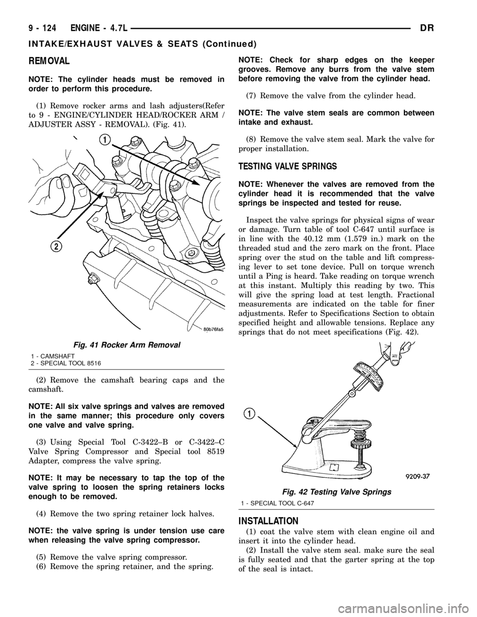
(1) Remove rocker arms and lash adjusters(Refer
to 9 - ENGINE/CYLINDER HEAD/ROCKER ARM /
ADJUSTER ASSY - REMOVAL). (Fig. 41).
(2) Remove the camshaft bearing caps and the
camshaft.
NOTE: All six valve springs and valves are removed
in the same manner; this procedure only covers
one valve and valve spring.
(3) Using Special Tool C-3422±B or C-3422±C
Valve Spring Compressor and Special tool 8519
Adapter, compress the valve spring.
NOTE: It may be necessary to tap the top of the
valve spring to loosen the spring retainers locks
enough to be removed.
(4) Remove the two spring retainer lock halves.
NOTE: the valve spring is under tension use care
when releasing the valve spring compressor.
(5) Remove the valve spring compressor.
(6) Remove the spring retainer, and the spring.NOTE: Check for sharp edges on the keeper
grooves. Remove any burrs from the valve stem
before removing the valve from the cylinder head.
(7) Remove the valve from the cylinder head.
NOTE: The valve stem seals are common between
intake and exhaust.
(8) Remove the valve stem seal. Mark the valve for
proper installation.
TESTING VALVE SPRINGS
NOTE: Whenever the valves are removed from the
cylinder head it is recommended that the valve
springs be inspected and tested for reuse.
Inspect the valve springs for physical signs of wear
or damage. Turn table of tool C-647 until surface is
in line with the 40.12 mm (1.579 in.) mark on the
threaded stud and the zero mark on the front. Place
spring over the stud on the table and lift compress-
ing lever to set tone device. Pull on torque wrench
until a Ping is heard. Take reading on torque wrench
at this instant. Multiply this reading by two. This
will give the spring load at test length. Fractional
measurements are indicated on the table for finer
adjustments. Refer to Specifications Section to obtain
specified height and allowable tensions. Replace any
springs that do not meet specifications (Fig. 42).
INSTALLATION
(1) coat the valve stem with clean engine oil and
insert it into the cylinder head.
(2) Install the valve stem seal. make sure the seal
is fully seated and that the garter spring at the top
of the seal is intact.
Fig. 41 Rocker Arm Removal
1 - CAMSHAFT
2 - SPECIAL TOOL 8516
Fig. 42 Testing Valve Springs
1 - SPECIAL TOOL C-647
9 - 124 ENGINE - 4.7LDR
INTAKE/EXHAUST VALVES & SEATS (Continued)
Page 1349 of 2627
base circle. Depress part of rocker arm over adjuster.
Normal adjusters should feel very firm. Spongy
adjusters can be bottomed out easily.
b. Remove suspected lash adjusters, and replace.
c. Before installation, make sure adjusters are at
least partially full of oil. This can be verified by little
or no plunger travel when lash adjuster is depressed.
REMOVAL
NOTE: Disconnect the battery negative cable to pre-
vent accidental starter engagement.
(1) Remove the cylinder head cover (Refer to 9 -
ENGINE/CYLINDER HEAD/CYLINDER HEAD
COVER(S) - REMOVAL).
(2) For rocker arm removal on cylinders 3 and 5
Rotate the crankshaft until cylinder #1 is at TDC
exhaust stroke.
(3) For rocker arm removal on cylinders 2 and 8
Rotate the crankshaft until cylinder #1 is at TDC
compression stroke.
(4) For rocker arm removal on cylinders 4 and 6
Rotate the crankshaft until cylinder #3 is at TDC
compression stroke.
(5) For rocker arm removal on cylinders 1 and 7
Rotate the crankshaft until cylinder #2 is at TDC
compression stroke.
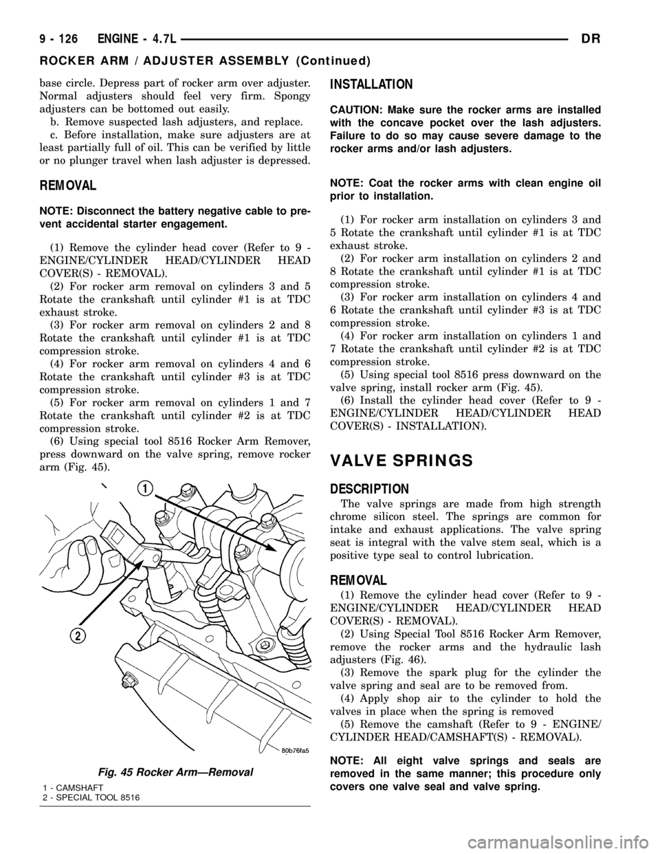
(6) Using special tool 8516 Rocker Arm Remover,
press downward on the valve spring, remove rocker
arm (Fig. 45).
INSTALLATION
CAUTION: Make sure the rocker arms are installed
with the concave pocket over the lash adjusters.
Failure to do so may cause severe damage to the
rocker arms and/or lash adjusters.
NOTE: Coat the rocker arms with clean engine oil
prior to installation.
(1) For rocker arm installation on cylinders 3 and
5 Rotate the crankshaft until cylinder #1 is at TDC
exhaust stroke.
(2) For rocker arm installation on cylinders 2 and
8 Rotate the crankshaft until cylinder #1 is at TDC
compression stroke.
(3) For rocker arm installation on cylinders 4 and
6 Rotate the crankshaft until cylinder #3 is at TDC
compression stroke.
(4) For rocker arm installation on cylinders 1 and
7 Rotate the crankshaft until cylinder #2 is at TDC
compression stroke.
(5) Using special tool 8516 press downward on the
valve spring, install rocker arm (Fig. 45).
(6) Install the cylinder head cover (Refer to 9 -
ENGINE/CYLINDER HEAD/CYLINDER HEAD
COVER(S) - INSTALLATION).
VALVE SPRINGS
DESCRIPTION
The valve springs are made from high strength
chrome silicon steel. The springs are common for
intake and exhaust applications. The valve spring
seat is integral with the valve stem seal, which is a
positive type seal to control lubrication.
REMOVAL
(1) Remove the cylinder head cover (Refer to 9 -
ENGINE/CYLINDER HEAD/CYLINDER HEAD
COVER(S) - REMOVAL).
(2) Using Special Tool 8516 Rocker Arm Remover,
remove the rocker arms and the hydraulic lash
adjusters (Fig. 46).
(3) Remove the spark plug for the cylinder the
valve spring and seal are to be removed from.
(4) Apply shop air to the cylinder to hold the
valves in place when the spring is removed
(5) Remove the camshaft (Refer to 9 - ENGINE/
CYLINDER HEAD/CAMSHAFT(S) - REMOVAL).
NOTE: All eight valve springs and seals are
removed in the same manner; this procedure only
covers one valve seal and valve spring.
Fig. 45 Rocker ArmÐRemoval
1 - CAMSHAFT
2 - SPECIAL TOOL 8516
9 - 126 ENGINE - 4.7LDR
ROCKER ARM / ADJUSTER ASSEMBLY (Continued)
Page 1350 of 2627
(6) Using Special Tool 8387 Valve Spring Compres-
sor, compress the valve spring.
NOTE: It may be necessary to tap the top of the
valve spring to loosen the spring retainers locks
enough to be removed.
(7) Remove the two spring retainer lock halves.
NOTE: the valve spring is under tension use care
when releasing the valve spring compressor.
(8) Remove the valve spring compressor.
(9) Remove the spring retainer, and the spring.
(10) Remove the valve stem seal.
NOTE: The valve stem seals are common between
intake and exhaust.
INSTALLATION
(1) coat the valve stem with clean engine oil and
install the valve stem seal. Make sure the seal is
fully seated and that the garter spring at the top of
the seal is intact.
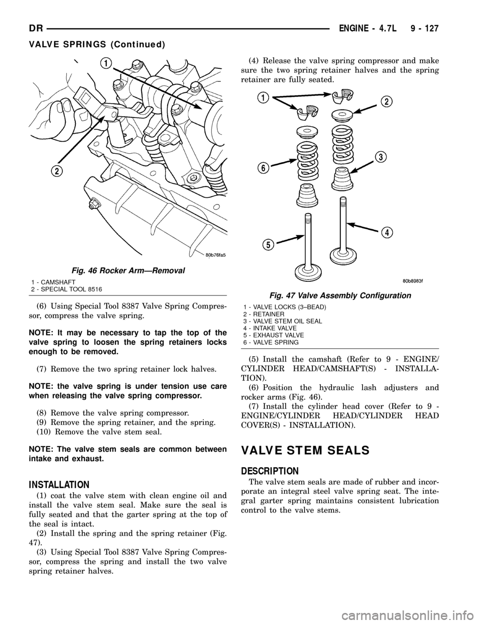
(2) Install the spring and the spring retainer (Fig.
47).
(3) Using Special Tool 8387 Valve Spring Compres-
sor, compress the spring and install the two valve
spring retainer halves.(4) Release the valve spring compressor and make
sure the two spring retainer halves and the spring
retainer are fully seated.
(5) Install the camshaft (Refer to 9 - ENGINE/
CYLINDER HEAD/CAMSHAFT(S) - INSTALLA-
TION).
(6) Position the hydraulic lash adjusters and
rocker arms (Fig. 46).
(7) Install the cylinder head cover (Refer to 9 -
ENGINE/CYLINDER HEAD/CYLINDER HEAD
COVER(S) - INSTALLATION).
VALVE STEM SEALS
DESCRIPTION
The valve stem seals are made of rubber and incor-
porate an integral steel valve spring seat. The inte-
gral garter spring maintains consistent lubrication
control to the valve stems.
Fig. 46 Rocker ArmÐRemoval
1 - CAMSHAFT
2 - SPECIAL TOOL 8516
Fig. 47 Valve Assembly Configuration
1 - VALVE LOCKS (3±BEAD)
2 - RETAINER
3 - VALVE STEM OIL SEAL
4 - INTAKE VALVE
5 - EXHAUST VALVE
6 - VALVE SPRING
DRENGINE - 4.7L 9 - 127
VALVE SPRINGS (Continued)
Page 1354 of 2627
CORE PLUGS
REMOVAL
(1) Drain the cooling system (Refer to 7 - COOL-
ING - STANDARD PROCEDURE).
(2) Using a blunt tool such as a drift or a screw
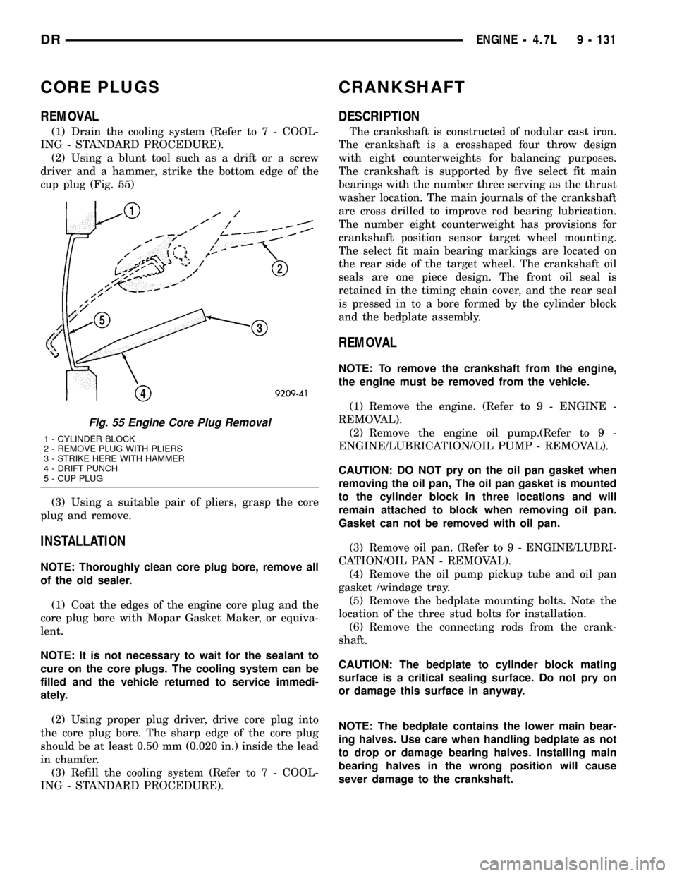
driver and a hammer, strike the bottom edge of the
cup plug (Fig. 55)
(3) Using a suitable pair of pliers, grasp the core
plug and remove.
INSTALLATION
NOTE: Thoroughly clean core plug bore, remove all
of the old sealer.
(1) Coat the edges of the engine core plug and the
core plug bore with Mopar Gasket Maker, or equiva-
lent.
NOTE: It is not necessary to wait for the sealant to
cure on the core plugs. The cooling system can be
filled and the vehicle returned to service immedi-
ately.
(2) Using proper plug driver, drive core plug into
the core plug bore. The sharp edge of the core plug
should be at least 0.50 mm (0.020 in.) inside the lead
in chamfer.
(3) Refill the cooling system (Refer to 7 - COOL-
ING - STANDARD PROCEDURE).
CRANKSHAFT
DESCRIPTION
The crankshaft is constructed of nodular cast iron.
The crankshaft is a crosshaped four throw design
with eight counterweights for balancing purposes.
The crankshaft is supported by five select fit main
bearings with the number three serving as the thrust
washer location. The main journals of the crankshaft
are cross drilled to improve rod bearing lubrication.
The number eight counterweight has provisions for
crankshaft position sensor target wheel mounting.
The select fit main bearing markings are located on
the rear side of the target wheel. The crankshaft oil
seals are one piece design. The front oil seal is
retained in the timing chain cover, and the rear seal
is pressed in to a bore formed by the cylinder block
and the bedplate assembly.
REMOVAL
NOTE: To remove the crankshaft from the engine,
the engine must be removed from the vehicle.
(1) Remove the engine. (Refer to 9 - ENGINE -
REMOVAL).
(2) Remove the engine oil pump.(Refer to 9 -
ENGINE/LUBRICATION/OIL PUMP - REMOVAL).
CAUTION: DO NOT pry on the oil pan gasket when
removing the oil pan, The oil pan gasket is mounted
to the cylinder block in three locations and will
remain attached to block when removing oil pan.
Gasket can not be removed with oil pan.
(3) Remove oil pan. (Refer to 9 - ENGINE/LUBRI-
CATION/OIL PAN - REMOVAL).
(4) Remove the oil pump pickup tube and oil pan
gasket /windage tray.
(5) Remove the bedplate mounting bolts. Note the
location of the three stud bolts for installation.
(6) Remove the connecting rods from the crank-
shaft.
CAUTION: The bedplate to cylinder block mating
surface is a critical sealing surface. Do not pry on
or damage this surface in anyway.
NOTE: The bedplate contains the lower main bear-
ing halves. Use care when handling bedplate as not
to drop or damage bearing halves. Installing main
bearing halves in the wrong position will cause
sever damage to the crankshaft.
Fig. 55 Engine Core Plug Removal
1 - CYLINDER BLOCK
2 - REMOVE PLUG WITH PLIERS
3 - STRIKE HERE WITH HAMMER
4 - DRIFT PUNCH
5 - CUP PLUG
DRENGINE - 4.7L 9 - 131
Page 1358 of 2627
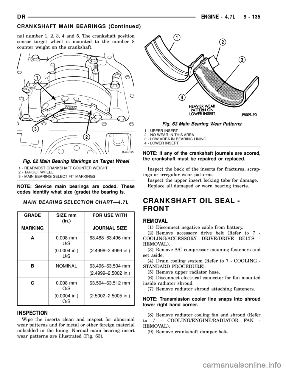
nal number 1, 2, 3, 4 and 5. The crankshaft position
sensor target wheel is mounted to the number 8
counter weight on the crankshaft.
NOTE: Service main bearings are coded. These
codes identify what size (grade) the bearing is.
MAIN BEARING SELECTION CHARTÐ4.7L
GRADE SIZE mm
(in.)FOR USE WITH
MARKING JOURNAL SIZE
A0.008 mm
U/S63.488±63.496 mm
(0.0004 in.)
U/S(2.4996±2.4999 in.)
BNOMINAL 63.496±63.504 mm
(2.4999±2.5002 in.)
C0.008 mm
O/S63.504±63.512 mm
(0.0004 in.)
O/S(2.5002±2.5005 in.)
INSPECTION
Wipe the inserts clean and inspect for abnormal
wear patterns and for metal or other foreign material
imbedded in the lining. Normal main bearing insert
wear patterns are illustrated (Fig. 63).NOTE: If any of the crankshaft journals are scored,
the crankshaft must be repaired or replaced.
Inspect the back of the inserts for fractures, scrap-
ings or irregular wear patterns.
Inspect the upper insert locking tabs for damage.
Replace all damaged or worn bearing inserts.
CRANKSHAFT OIL SEAL -
FRONT
REMOVAL
(1) Disconnect negative cable from battery.
(2) Remove accessory drive belt (Refer to 7 -
COOLING/ACCESSORY DRIVE/DRIVE BELTS -
REMOVAL).
(3) Remove A/C compressor mouning fasteners and
set aside.
(4) Drain cooling system (Refer to 7 - COOLING -
STANDARD PROCEDURE).
(5) Remove upper radiator hose.
(6) Disconnect electrical connector for fan mounted
inside radiator shroud.
(7) Remove radiator shroud attaching fasteners.
NOTE: Transmission cooler line snaps into shroud
lower right hand corner.
(8) Remove radiator cooling fan and shroud (Refer
to 7 - COOLING/ENGINE/RADIATOR FAN -
REMOVAL).
(9) Remove crankshaft damper bolt.
Fig. 62 Main Bearing Markings on Target Wheel
1 - REARMOST CRANKSHAFT COUNTER WEIGHT
2 - TARGET WHEEL
3 - MAIN BEARING SELECT FIT MARKINGS
Fig. 63 Main Bearing Wear Patterns
1 - UPPER INSERT
2 - NO WEAR IN THIS AREA
3 - LOW AREA IN BEARING LINING
4 - LOWER INSERT
DRENGINE - 4.7L 9 - 135
CRANKSHAFT MAIN BEARINGS (Continued)
Page 1359 of 2627
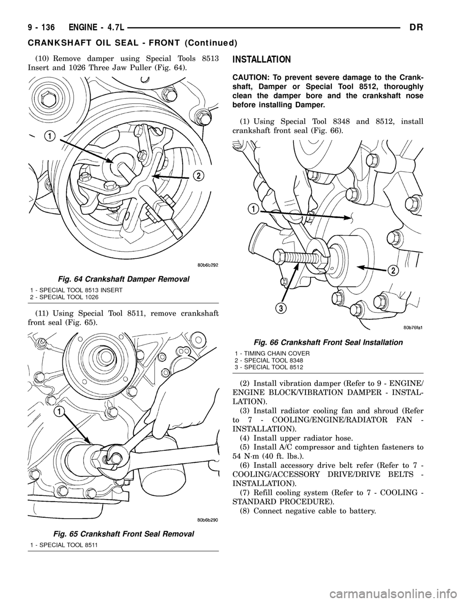
(10) Remove damper using Special Tools 8513
Insert and 1026 Three Jaw Puller (Fig. 64).
(11) Using Special Tool 8511, remove crankshaft
front seal (Fig. 65).INSTALLATION
CAUTION: To prevent severe damage to the Crank-
shaft, Damper or Special Tool 8512, thoroughly
clean the damper bore and the crankshaft nose
before installing Damper.
(1) Using Special Tool 8348 and 8512, install
crankshaft front seal (Fig. 66).
(2) Install vibration damper (Refer to 9 - ENGINE/
ENGINE BLOCK/VIBRATION DAMPER - INSTAL-
LATION).
(3) Install radiator cooling fan and shroud (Refer
to 7 - COOLING/ENGINE/RADIATOR FAN -
INSTALLATION).
(4) Install upper radiator hose.
(5) Install A/C compressor and tighten fasteners to
54 N´m (40 ft. lbs.).
(6) Install accessory drive belt refer (Refer to 7 -
COOLING/ACCESSORY DRIVE/DRIVE BELTS -
INSTALLATION).
(7) Refill cooling system (Refer to 7 - COOLING -
STANDARD PROCEDURE).
(8) Connect negative cable to battery.
Fig. 64 Crankshaft Damper Removal
1 - SPECIAL TOOL 8513 INSERT
2 - SPECIAL TOOL 1026
Fig. 65 Crankshaft Front Seal Removal
1 - SPECIAL TOOL 8511
Fig. 66 Crankshaft Front Seal Installation
1 - TIMING CHAIN COVER
2 - SPECIAL TOOL 8348
3 - SPECIAL TOOL 8512
9 - 136 ENGINE - 4.7LDR
CRANKSHAFT OIL SEAL - FRONT (Continued)
Page 1360 of 2627
CRANKSHAFT OIL SEAL -
REAR
DIAGNOSIS AND TESTING - REAR SEAL AREA
LEAKS
Since it is sometimes difficult to determine the
source of an oil leak in the rear seal area of the
engine, a more involved inspection is necessary. The
following steps should be followed to help pinpoint
the source of the leak.
If the leakage occurs at the crankshaft rear oil seal
area:
(1) Disconnect the battery.
(2) Raise the vehicle.
(3) Remove torque converter or clutch housing
cover and inspect rear of block for evidence of oil.
Use a black light to check for the oil leak:
(a) Circular spray pattern generally indicates
seal leakage or crankshaft damage.
(b) Where leakage tends to run straight down,
possible causes are a porous block, camshaft bore
cup plugs, oil galley pipe plugs, oil filter runoff,
and main bearing cap to cylinder block mating sur-
faces. See Engine, for proper repair procedures of
these items.
(4) If no leaks are detected, pressurized the crank-
case as outlined in the section, Inspection (Engine oil
Leaks in general)
CAUTION: Do not exceed 20.6 kPa (3 psi).
(5) If the leak is not detected, very slowly turn the
crankshaft and watch for leakage. If a leak is
detected between the crankshaft and seal while
slowly turning the crankshaft, it is possible the
crankshaft seal surface is damaged. The seal area on
the crankshaft could have minor nicks or scratches
that can be polished out with emery cloth.
CAUTION: Use extreme caution when crankshaft
polishing is necessary to remove minor nicks or
scratches. The crankshaft seal flange is specially
machined to complement the function of the rear oil
seal.
(6) For bubbles that remain steady with shaft
rotation, no further inspection can be done until dis-
assembled. (Refer to 9 - ENGINE - DIAGNOSIS AND
TESTING), under the Oil Leak row, for components
inspections on possible causes and corrections.
(7) After the oil leak root cause and appropriate
corrective action have been identified, (Refer to 9 -
ENGINE/ENGINE BLOCK/CRANKSHAFT OIL
SEAL - REAR - REMOVAL).
REMOVAL
NOTE: This procedure can be performed in vehicle.
(1) If being preformed in vehicle, remove the
transmission.
(2) Remove the flexplate (Refer to 9 - ENGINE/
ENGINE BLOCK/FLEX PLATE - REMOVAL).
NOTE: The crankshaft oil seal CAN NOT be reused
after removal.
NOTE: The crankshaft rear oil seal remover Special
Tool 8506 must be installed deeply into the seal.
Continue to tighten the removal tool into the seal
until the tool can not be turned farther. Failure to
install tool correctly the first time will cause tool to
pull free of seal without removing seal from engine.
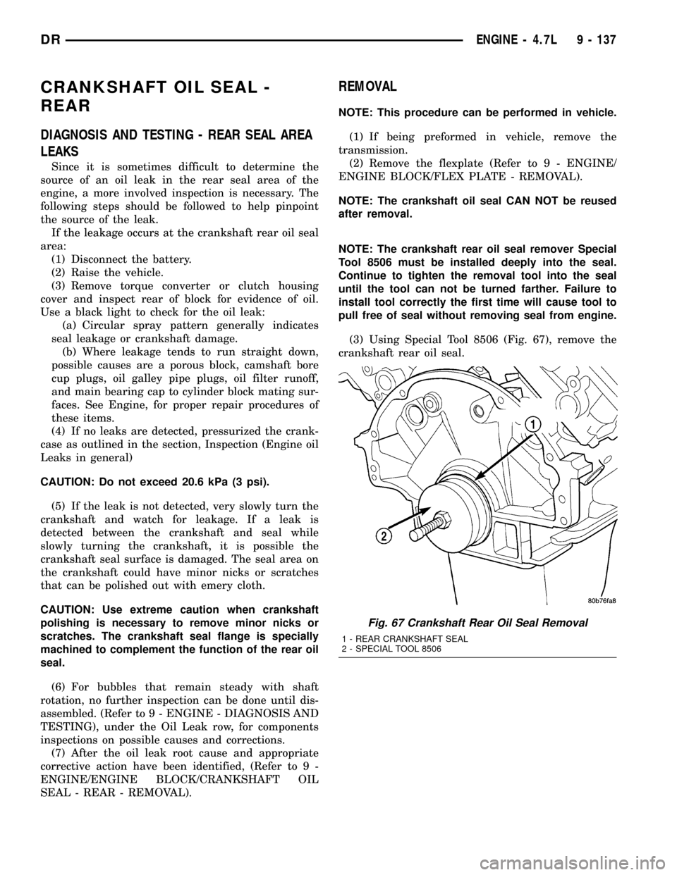
(3) Using Special Tool 8506 (Fig. 67), remove the
crankshaft rear oil seal.
Fig. 67 Crankshaft Rear Oil Seal Removal
1 - REAR CRANKSHAFT SEAL
2 - SPECIAL TOOL 8506
DRENGINE - 4.7L 9 - 137
Page 1361 of 2627
INSTALLATION
(1) Lubricate the crankshaft flange with engine oil.
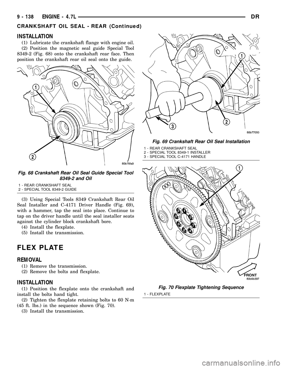
(2) Position the magnetic seal guide Special Tool
8349-2 (Fig. 68) onto the crankshaft rear face. Then
position the crankshaft rear oil seal onto the guide.
(3) Using Special Tools 8349 Crankshaft Rear Oil
Seal Installer and C-4171 Driver Handle (Fig. 69),
with a hammer, tap the seal into place. Continue to
tap on the driver handle until the seal installer seats
against the cylinder block crankshaft bore.
(4) Install the flexplate.
(5) Install the transmission.
FLEX PLATE
REMOVAL
(1) Remove the transmission.
(2) Remove the bolts and flexplate.
INSTALLATION
(1) Position the flexplate onto the crankshaft and
install the bolts hand tight.
(2) Tighten the flexplate retaining bolts to 60 N´m
(45 ft. lbs.) in the sequence shown (Fig. 70).
(3) Install the transmission.
Fig. 68 Crankshaft Rear Oil Seal Guide Special Tool
8349-2 and Oil
1 - REAR CRANKSHAFT SEAL
2 - SPECIAL TOOL 8349-2 GUIDE
Fig. 69 Crankshaft Rear Oil Seal Installation
1 - REAR CRANKSHAFT SEAL
2 - SPECIAL TOOL 8349-1 INSTALLER
3 - SPECIAL TOOL C-4171 HANDLE
Fig. 70 Flexplate Tightening Sequence
1 - FLEXPLATE
9 - 138 ENGINE - 4.7LDR
CRANKSHAFT OIL SEAL - REAR (Continued)