1998 DODGE RAM 1500 Head gasket
[x] Cancel search: Head gasketPage 1332 of 2627
NOTE: Mark the secondary timing chain prior to
removal to aid in installation.
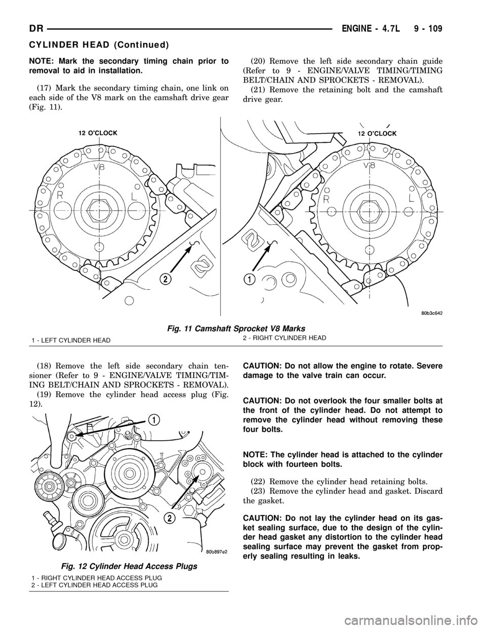
(17) Mark the secondary timing chain, one link on
each side of the V8 mark on the camshaft drive gear
(Fig. 11).
(18) Remove the left side secondary chain ten-
sioner (Refer to 9 - ENGINE/VALVE TIMING/TIM-
ING BELT/CHAIN AND SPROCKETS - REMOVAL).
(19) Remove the cylinder head access plug (Fig.
12).(20) Remove the left side secondary chain guide
(Refer to 9 - ENGINE/VALVE TIMING/TIMING
BELT/CHAIN AND SPROCKETS - REMOVAL).
(21) Remove the retaining bolt and the camshaft
drive gear.
CAUTION: Do not allow the engine to rotate. Severe
damage to the valve train can occur.
CAUTION: Do not overlook the four smaller bolts at
the front of the cylinder head. Do not attempt to
remove the cylinder head without removing these
four bolts.
NOTE: The cylinder head is attached to the cylinder
block with fourteen bolts.
(22) Remove the cylinder head retaining bolts.
(23) Remove the cylinder head and gasket. Discard
the gasket.
CAUTION: Do not lay the cylinder head on its gas-
ket sealing surface, due to the design of the cylin-
der head gasket any distortion to the cylinder head
sealing surface may prevent the gasket from prop-
erly sealing resulting in leaks.
Fig. 11 Camshaft Sprocket V8 Marks
1 - LEFT CYLINDER HEAD2 - RIGHT CYLINDER HEAD
Fig. 12 Cylinder Head Access Plugs
1 - RIGHT CYLINDER HEAD ACCESS PLUG
2 - LEFT CYLINDER HEAD ACCESS PLUG
DRENGINE - 4.7L 9 - 109
CYLINDER HEAD (Continued)
Page 1334 of 2627
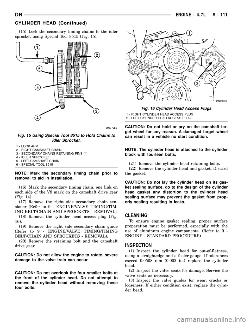
(15) Lock the secondary timing chains to the idler
sprocket using Special Tool 8515 (Fig. 15).
NOTE: Mark the secondary timing chain prior to
removal to aid in installation.
(16) Mark the secondary timing chain, one link on
each side of the V8 mark on the camshaft drive gear
(Fig. 14).
(17) Remove the right side secondary chain ten-
sioner (Refer to 9 - ENGINE/VALVE TIMING/TIM-
ING BELT/CHAIN AND SPROCKETS - REMOVAL).
(18) Remove the cylinder head access plug (Fig.
16).
(19) Remove the right side secondary chain guide
(Refer to 9 - ENGINE/VALVE TIMING/TIMING
BELT/CHAIN AND SPROCKETS - REMOVAL).
(20) Remove the retaining bolt and the camshaft
drive gear.
CAUTION: Do not allow the engine to rotate. severe
damage to the valve train can occur.
CAUTION: Do not overlook the four smaller bolts at
the front of the cylinder head. Do not attempt to
remove the cylinder head without removing these
four bolts.CAUTION: Do not hold or pry on the camshaft tar-
get wheel for any reason. A damaged target wheel
can result in a vehicle no start condition.
NOTE: The cylinder head is attached to the cylinder
block with fourteen bolts.
(21) Remove the cylinder head retaining bolts.
(22) Remove the cylinder head and gasket. Discard
the gasket.
CAUTION: Do not lay the cylinder head on its gas-
ket sealing surface, do to the design of the cylinder
head gasket any distortion to the cylinder head
sealing surface may prevent the gasket from prop-
erly sealing resulting in leaks.
CLEANING
To ensure engine gasket sealing, proper surface
preparation must be performed, especially with the
use of aluminum engine components. (Refer to 9 -
ENGINE - STANDARD PROCEDURE)
INSPECTION
(1) Inspect the cylinder head for out-of-flatness,
using a straightedge and a feeler gauge. If tolerances
exceed 0.0508 mm (0.002 in.) replace the cylinder
head.
(2) Inspect the valve seats for damage. Service the
valve seats as necessary.
(3) Inspect the valve guides for wear, cracks or
looseness. If either condition exist, replace the cylin-
der head.
Fig. 15 Using Special Tool 8515 to Hold Chains to
Idler Sprocket.
1 - LOCK ARM
2 - RIGHT CAMSHAFT CHAIN
3 - SECONDARY CHAINS RETAINING PINS (4)
4 - IDLER SPROCKET
5 - LEFT CAMSHAFT CHAIN
6 - SPECIAL TOOL 8515
Fig. 16 Cylinder Head Access Plugs
1 - RIGHT CYLINDER HEAD ACCESS PLUG
2 - LEFT CYLINDER HEAD ACCESS PLUG
DRENGINE - 4.7L 9 - 111
CYLINDER HEAD (Continued)
Page 1335 of 2627
INSTALLATION
INSTALLATION - LEFT CYLINDER HEAD
NOTE: The cylinder head bolts are tightened using
a torque plus angle procedure. The bolts must be
examined BEFORE reuse. If the threads are necked
down the bolts should be replaced.
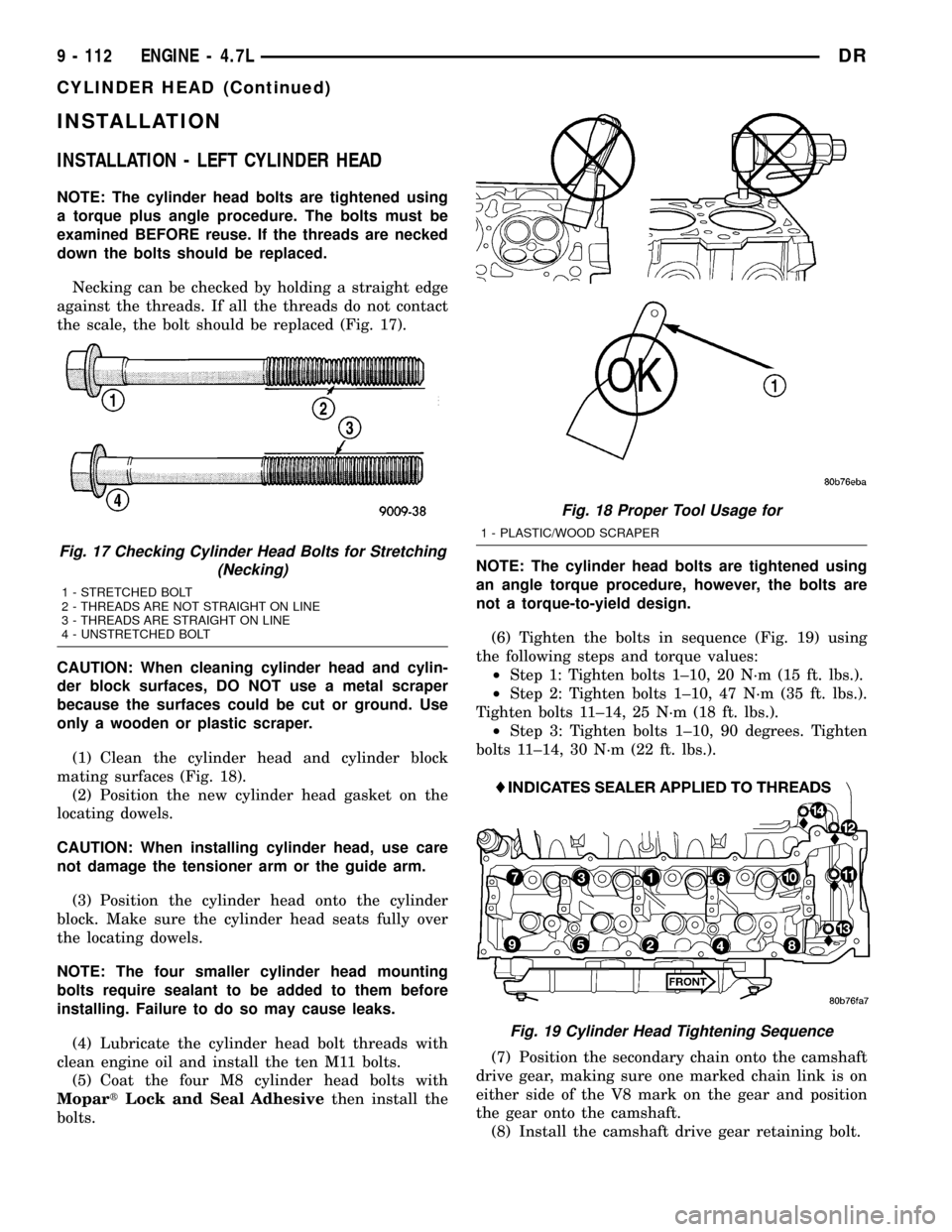
Necking can be checked by holding a straight edge
against the threads. If all the threads do not contact
the scale, the bolt should be replaced (Fig. 17).
CAUTION: When cleaning cylinder head and cylin-
der block surfaces, DO NOT use a metal scraper
because the surfaces could be cut or ground. Use
only a wooden or plastic scraper.
(1) Clean the cylinder head and cylinder block
mating surfaces (Fig. 18).
(2) Position the new cylinder head gasket on the
locating dowels.
CAUTION: When installing cylinder head, use care
not damage the tensioner arm or the guide arm.
(3) Position the cylinder head onto the cylinder
block. Make sure the cylinder head seats fully over
the locating dowels.
NOTE: The four smaller cylinder head mounting
bolts require sealant to be added to them before
installing. Failure to do so may cause leaks.
(4) Lubricate the cylinder head bolt threads with
clean engine oil and install the ten M11 bolts.
(5) Coat the four M8 cylinder head bolts with
MopartLock and Seal Adhesivethen install the
bolts.NOTE: The cylinder head bolts are tightened using
an angle torque procedure, however, the bolts are
not a torque-to-yield design.
(6) Tighten the bolts in sequence (Fig. 19) using
the following steps and torque values:
²Step 1: Tighten bolts 1±10, 20 N´m (15 ft. lbs.).
²Step 2: Tighten bolts 1±10, 47 N´m (35 ft. lbs.).
Tighten bolts 11±14, 25 N´m (18 ft. lbs.).
²Step 3: Tighten bolts 1±10, 90 degrees. Tighten
bolts 11±14, 30 N´m (22 ft. lbs.).
(7) Position the secondary chain onto the camshaft
drive gear, making sure one marked chain link is on
either side of the V8 mark on the gear and position
the gear onto the camshaft.
(8) Install the camshaft drive gear retaining bolt.
Fig. 17 Checking Cylinder Head Bolts for Stretching
(Necking)
1 - STRETCHED BOLT
2 - THREADS ARE NOT STRAIGHT ON LINE
3 - THREADS ARE STRAIGHT ON LINE
4 - UNSTRETCHED BOLT
Fig. 18 Proper Tool Usage for
1 - PLASTIC/WOOD SCRAPER
Fig. 19 Cylinder Head Tightening Sequence
9 - 112 ENGINE - 4.7LDR
CYLINDER HEAD (Continued)
Page 1336 of 2627
(9) Install the left side secondary chain guide
(Refer to 9 - ENGINE/VALVE TIMING/TIMING
BELT/CHAIN AND SPROCKETS - INSTALLA-
TION).
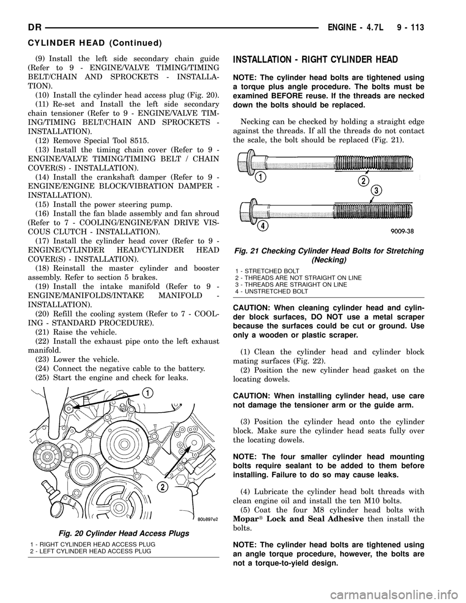
(10) Install the cylinder head access plug (Fig. 20).
(11) Re-set and Install the left side secondary
chain tensioner (Refer to 9 - ENGINE/VALVE TIM-
ING/TIMING BELT/CHAIN AND SPROCKETS -
INSTALLATION).
(12) Remove Special Tool 8515.
(13) Install the timing chain cover (Refer to 9 -
ENGINE/VALVE TIMING/TIMING BELT / CHAIN
COVER(S) - INSTALLATION).
(14) Install the crankshaft damper (Refer to 9 -
ENGINE/ENGINE BLOCK/VIBRATION DAMPER -
INSTALLATION).
(15) Install the power steering pump.
(16) Install the fan blade assembly and fan shroud
(Refer to 7 - COOLING/ENGINE/FAN DRIVE VIS-
COUS CLUTCH - INSTALLATION).
(17) Install the cylinder head cover (Refer to 9 -
ENGINE/CYLINDER HEAD/CYLINDER HEAD
COVER(S) - INSTALLATION).
(18) Reinstall the master cylinder and booster
assembly. Refer to section 5 brakes.
(19) Install the intake manifold (Refer to 9 -
ENGINE/MANIFOLDS/INTAKE MANIFOLD -
INSTALLATION).
(20) Refill the cooling system (Refer to 7 - COOL-
ING - STANDARD PROCEDURE).
(21) Raise the vehicle.
(22) Install the exhaust pipe onto the left exhaust
manifold.
(23) Lower the vehicle.
(24) Connect the negative cable to the battery.
(25) Start the engine and check for leaks.INSTALLATION - RIGHT CYLINDER HEAD
NOTE: The cylinder head bolts are tightened using
a torque plus angle procedure. The bolts must be
examined BEFORE reuse. If the threads are necked
down the bolts should be replaced.
Necking can be checked by holding a straight edge
against the threads. If all the threads do not contact
the scale, the bolt should be replaced (Fig. 21).
CAUTION: When cleaning cylinder head and cylin-
der block surfaces, DO NOT use a metal scraper
because the surfaces could be cut or ground. Use
only a wooden or plastic scraper.
(1) Clean the cylinder head and cylinder block
mating surfaces (Fig. 22).
(2) Position the new cylinder head gasket on the
locating dowels.
CAUTION: When installing cylinder head, use care
not damage the tensioner arm or the guide arm.
(3) Position the cylinder head onto the cylinder
block. Make sure the cylinder head seats fully over
the locating dowels.
NOTE: The four smaller cylinder head mounting
bolts require sealant to be added to them before
installing. Failure to do so may cause leaks.
(4) Lubricate the cylinder head bolt threads with
clean engine oil and install the ten M10 bolts.
(5) Coat the four M8 cylinder head bolts with
MopartLock and Seal Adhesivethen install the
bolts.
NOTE: The cylinder head bolts are tightened using
an angle torque procedure, however, the bolts are
not a torque-to-yield design.
Fig. 20 Cylinder Head Access Plugs
1 - RIGHT CYLINDER HEAD ACCESS PLUG
2 - LEFT CYLINDER HEAD ACCESS PLUG
Fig. 21 Checking Cylinder Head Bolts for Stretching
(Necking)
1 - STRETCHED BOLT
2 - THREADS ARE NOT STRAIGHT ON LINE
3 - THREADS ARE STRAIGHT ON LINE
4 - UNSTRETCHED BOLT
DRENGINE - 4.7L 9 - 113
CYLINDER HEAD (Continued)
Page 1345 of 2627
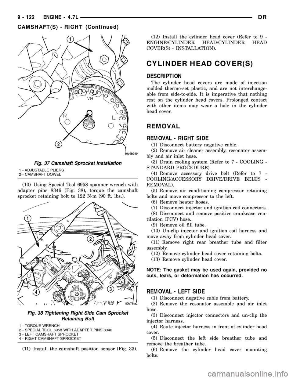
(10) Using Special Tool 6958 spanner wrench with
adapter pins 8346 (Fig. 38), torque the camshaft
sprocket retaining bolt to 122 N´m (90 ft. lbs.).
(11) Install the camshaft position sensor (Fig. 33).(12) Install the cylinder head cover (Refer to 9 -
ENGINE/CYLINDER HEAD/CYLINDER HEAD
COVER(S) - INSTALLATION).
CYLINDER HEAD COVER(S)
DESCRIPTION
The cylinder head covers are made of injection
molded thermo-set plastic, and are not interchange-
able from side-to-side. It is imperative that nothing
rest on the cylinder head covers. Prolonged contact
with other items may wear a hole in the cylinder
head cover.
REMOVAL
REMOVAL - RIGHT SIDE
(1) Disconnect battery negative cable.
(2) Remove air cleaner assembly, resonator assem-
bly and air inlet hose.
(3) Drain cooling system (Refer to 7 - COOLING -
STANDARD PROCEDURE).
(4) Remove accessory drive belt (Refer to 7 -
COOLING/ACCESSORY DRIVE/DRIVE BELTS -
REMOVAL).
(5) Remove air conditioning compressor retaining
bolts and move compressor to the left.
(6) Remove heater hoses.
(7) Disconnect injector and ignition coil connectors.
(8) Disconnect and remove positive crankcase ven-
tilation (PCV) hose.
(9) Remove oil fill tube.
(10) Un-clip injector and ignition coil harness and
move away from cylinder head cover.
(11) Remove right rear breather tube and filter
assembly.
(12) Remove cylinder head cover retaining bolts.
(13) Remove cylinder head cover.
NOTE: The gasket may be used again, provided no
cuts, tears, or deformation has occurred.
REMOVAL - LEFT SIDE
(1) Disconnect negative cable from battery.
(2) Remove the resonator assemble and air inlet
hose.
(3) Disconnect injector connectors and un-clip the
injector harness.
(4) Route injector harness in front of cylinder head
cover.
(5) Disconnect the left side breather tube and
remove the breather tube.
(6) Remove the cylinder head cover mounting
bolts.
Fig. 37 Camshaft Sprocket Installation
1 - ADJUSTABLE PLIERS
2 - CAMSHAFT DOWEL
Fig. 38 Tightening Right Side Cam Sprocket
Retaining Bolt
1 - TORQUE WRENCH
2 - SPECIAL TOOL 6958 WITH ADAPTER PINS 8346
3 - LEFT CAMSHAFT SPROCKET
4 - RIGHT CAMSHAFT SPROCKET
9 - 122 ENGINE - 4.7LDR
CAMSHAFT(S) - RIGHT (Continued)
Page 1346 of 2627
(7) Remove cylinder head cover and gasket.
NOTE: The gasket may be used again, provided no
cuts, tears, or deformation has occurred.
CLEANING
Clean cylinder head cover gasket surface.
Clean head rail, if necessary.
INSTALLATION
INSTALLATION - RIGHT SIDE
CAUTION: Do not use harsh cleaners to clean the
cylinder head covers. Severe damage to covers
may occur.
(1) Clean cylinder head cover and both sealing sur-
faces. Inspect and replace gasket as necessary.
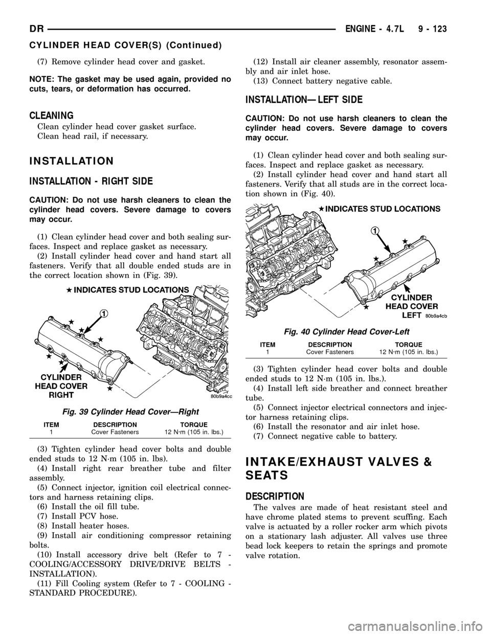
(2) Install cylinder head cover and hand start all
fasteners. Verify that all double ended studs are in
the correct location shown in (Fig. 39).
(3) Tighten cylinder head cover bolts and double
ended studs to 12 N´m (105 in. lbs).
(4) Install right rear breather tube and filter
assembly.
(5) Connect injector, ignition coil electrical connec-
tors and harness retaining clips.
(6) Install the oil fill tube.
(7) Install PCV hose.
(8) Install heater hoses.
(9) Install air conditioning compressor retaining
bolts.
(10) Install accessory drive belt (Refer to 7 -
COOLING/ACCESSORY DRIVE/DRIVE BELTS -
INSTALLATION).
(11) Fill Cooling system (Refer to 7 - COOLING -
STANDARD PROCEDURE).(12) Install air cleaner assembly, resonator assem-
bly and air inlet hose.
(13) Connect battery negative cable.
INSTALLATIONÐLEFT SIDE
CAUTION: Do not use harsh cleaners to clean the
cylinder head covers. Severe damage to covers
may occur.
(1) Clean cylinder head cover and both sealing sur-
faces. Inspect and replace gasket as necessary.
(2) Install cylinder head cover and hand start all
fasteners. Verify that all studs are in the correct loca-
tion shown in (Fig. 40).
(3) Tighten cylinder head cover bolts and double
ended studs to 12 N´m (105 in. lbs.).
(4) Install left side breather and connect breather
tube.
(5) Connect injector electrical connectors and injec-
tor harness retaining clips.
(6) Install the resonator and air inlet hose.
(7) Connect negative cable to battery.
INTAKE/EXHAUST VALVES &
SEATS
DESCRIPTION
The valves are made of heat resistant steel and
have chrome plated stems to prevent scuffing. Each
valve is actuated by a roller rocker arm which pivots
on a stationary lash adjuster. All valves use three
bead lock keepers to retain the springs and promote
valve rotation.
Fig. 39 Cylinder Head CoverÐRight
ITEM DESCRIPTION TORQUE
1 Cover Fasteners 12 N´m (105 in. lbs.)
Fig. 40 Cylinder Head Cover-Left
ITEM DESCRIPTION TORQUE
1 Cover Fasteners 12 N´m (105 in. lbs.)
DRENGINE - 4.7L 9 - 123
CYLINDER HEAD COVER(S) (Continued)
Page 1348 of 2627
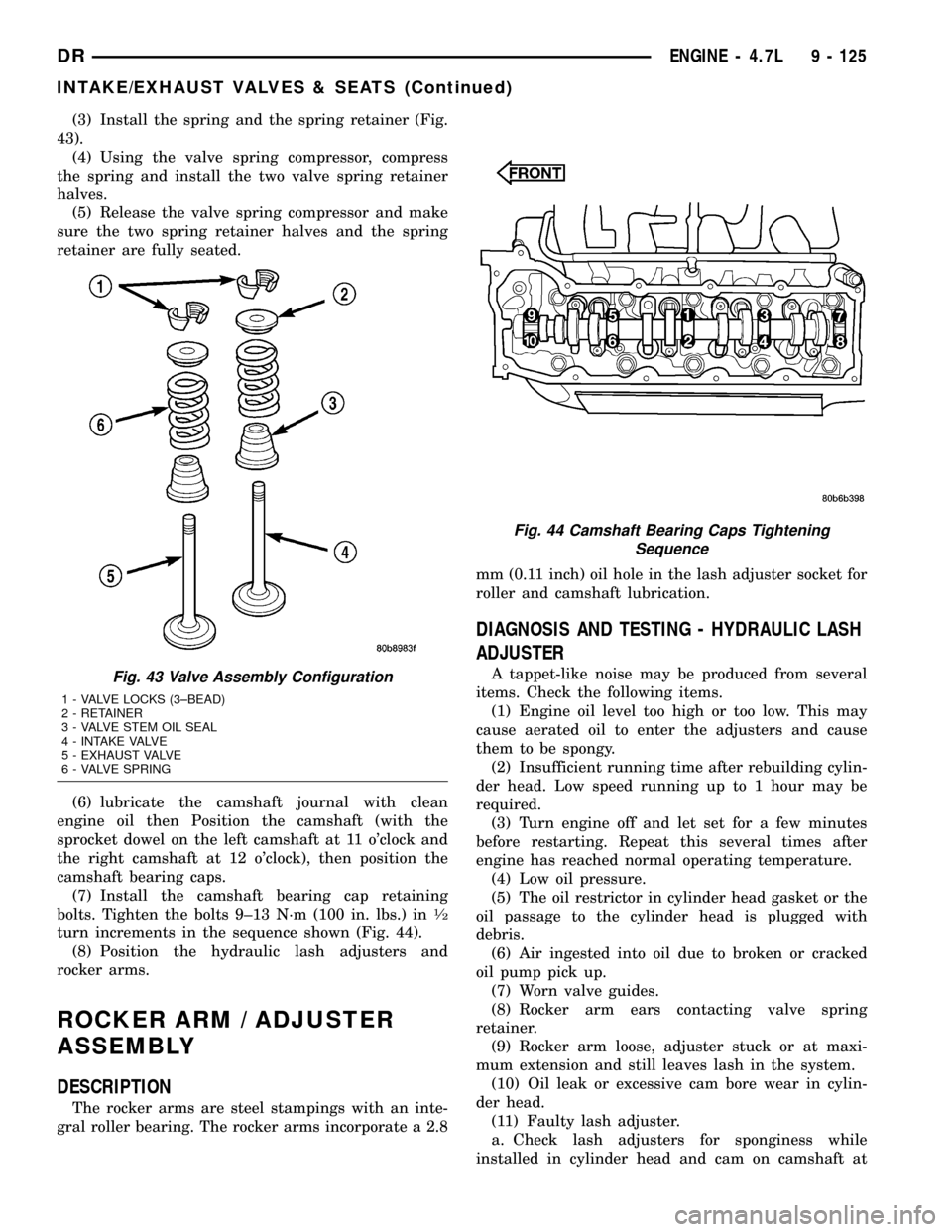
(3) Install the spring and the spring retainer (Fig.
43).
(4) Using the valve spring compressor, compress
the spring and install the two valve spring retainer
halves.
(5) Release the valve spring compressor and make
sure the two spring retainer halves and the spring
retainer are fully seated.
(6) lubricate the camshaft journal with clean
engine oil then Position the camshaft (with the
sprocket dowel on the left camshaft at 11 o'clock and
the right camshaft at 12 o'clock), then position the
camshaft bearing caps.
(7) Install the camshaft bearing cap retaining
bolts. Tighten the bolts 9±13 N´m (100 in. lbs.) in
1¤2
turn increments in the sequence shown (Fig. 44).
(8) Position the hydraulic lash adjusters and
rocker arms.
ROCKER ARM / ADJUSTER
ASSEMBLY
DESCRIPTION
The rocker arms are steel stampings with an inte-
gral roller bearing. The rocker arms incorporate a 2.8mm (0.11 inch) oil hole in the lash adjuster socket for
roller and camshaft lubrication.
DIAGNOSIS AND TESTING - HYDRAULIC LASH
ADJUSTER
A tappet-like noise may be produced from several
items. Check the following items.
(1) Engine oil level too high or too low. This may
cause aerated oil to enter the adjusters and cause
them to be spongy.
(2) Insufficient running time after rebuilding cylin-
der head. Low speed running up to 1 hour may be
required.
(3) Turn engine off and let set for a few minutes
before restarting. Repeat this several times after
engine has reached normal operating temperature.
(4) Low oil pressure.
(5) The oil restrictor in cylinder head gasket or the
oil passage to the cylinder head is plugged with
debris.
(6) Air ingested into oil due to broken or cracked
oil pump pick up.
(7) Worn valve guides.
(8) Rocker arm ears contacting valve spring
retainer.
(9) Rocker arm loose, adjuster stuck or at maxi-
mum extension and still leaves lash in the system.
(10) Oil leak or excessive cam bore wear in cylin-
der head.
(11) Faulty lash adjuster.
a. Check lash adjusters for sponginess while
installed in cylinder head and cam on camshaft atFig. 43 Valve Assembly Configuration
1 - VALVE LOCKS (3±BEAD)
2 - RETAINER
3 - VALVE STEM OIL SEAL
4 - INTAKE VALVE
5 - EXHAUST VALVE
6 - VALVE SPRING
Fig. 44 Camshaft Bearing Caps Tightening
Sequence
DRENGINE - 4.7L 9 - 125
INTAKE/EXHAUST VALVES & SEATS (Continued)
Page 1355 of 2627
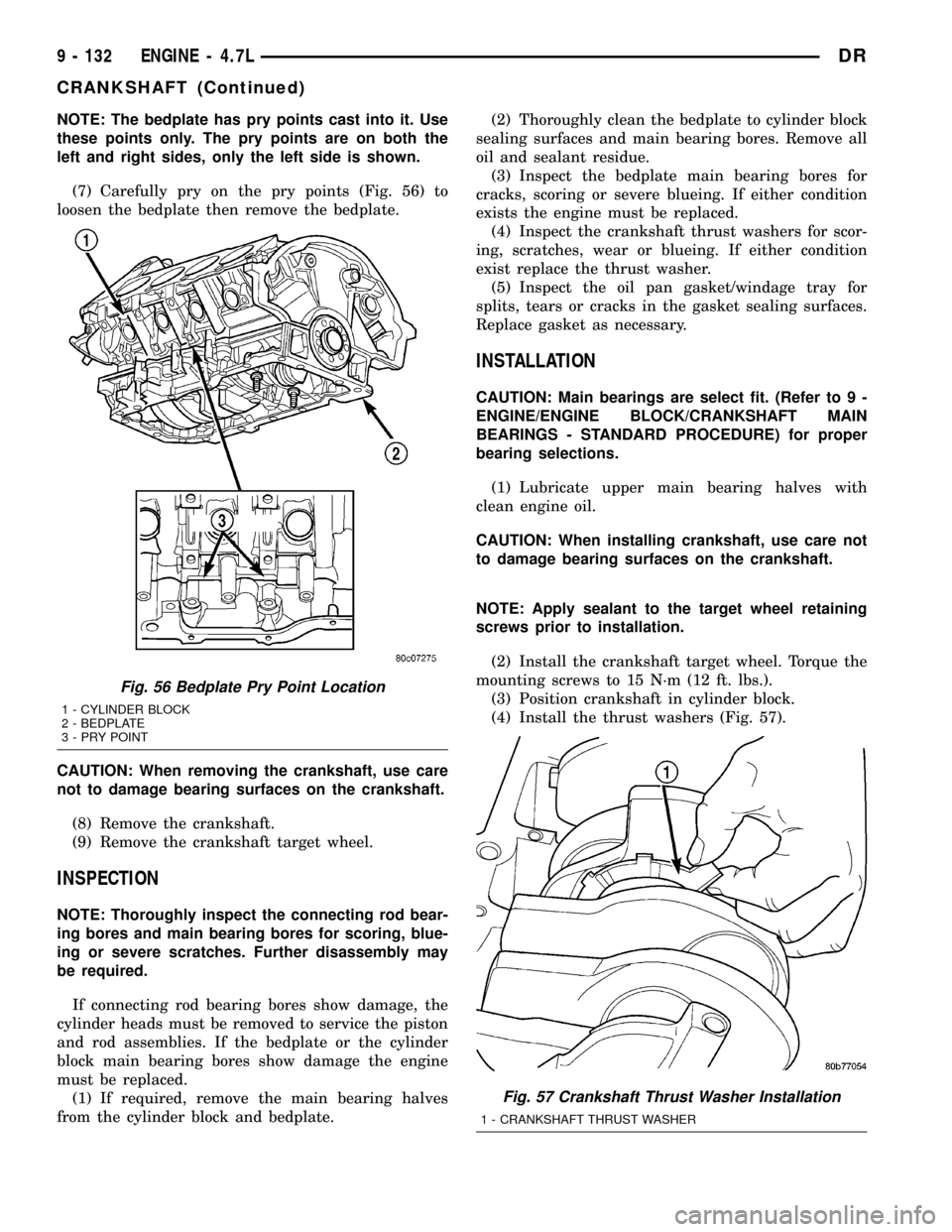
NOTE: The bedplate has pry points cast into it. Use
these points only. The pry points are on both the
left and right sides, only the left side is shown.
(7) Carefully pry on the pry points (Fig. 56) to
loosen the bedplate then remove the bedplate.
CAUTION: When removing the crankshaft, use care
not to damage bearing surfaces on the crankshaft.
(8) Remove the crankshaft.
(9) Remove the crankshaft target wheel.
INSPECTION
NOTE: Thoroughly inspect the connecting rod bear-
ing bores and main bearing bores for scoring, blue-
ing or severe scratches. Further disassembly may
be required.
If connecting rod bearing bores show damage, the
cylinder heads must be removed to service the piston
and rod assemblies. If the bedplate or the cylinder
block main bearing bores show damage the engine
must be replaced.
(1) If required, remove the main bearing halves
from the cylinder block and bedplate.(2) Thoroughly clean the bedplate to cylinder block
sealing surfaces and main bearing bores. Remove all
oil and sealant residue.
(3) Inspect the bedplate main bearing bores for
cracks, scoring or severe blueing. If either condition
exists the engine must be replaced.
(4) Inspect the crankshaft thrust washers for scor-
ing, scratches, wear or blueing. If either condition
exist replace the thrust washer.
(5) Inspect the oil pan gasket/windage tray for
splits, tears or cracks in the gasket sealing surfaces.
Replace gasket as necessary.
INSTALLATION
CAUTION: Main bearings are select fit. (Refer to 9 -
ENGINE/ENGINE BLOCK/CRANKSHAFT MAIN
BEARINGS - STANDARD PROCEDURE) for proper
bearing selections.
(1) Lubricate upper main bearing halves with
clean engine oil.
CAUTION: When installing crankshaft, use care not
to damage bearing surfaces on the crankshaft.
NOTE: Apply sealant to the target wheel retaining
screws prior to installation.
(2) Install the crankshaft target wheel. Torque the
mounting screws to 15 N´m (12 ft. lbs.).
(3) Position crankshaft in cylinder block.
(4) Install the thrust washers (Fig. 57).
Fig. 56 Bedplate Pry Point Location
1 - CYLINDER BLOCK
2 - BEDPLATE
3 - PRY POINT
Fig. 57 Crankshaft Thrust Washer Installation
1 - CRANKSHAFT THRUST WASHER
9 - 132 ENGINE - 4.7LDR
CRANKSHAFT (Continued)