1998 DODGE RAM 1500 Head gasket
[x] Cancel search: Head gasketPage 1228 of 2627
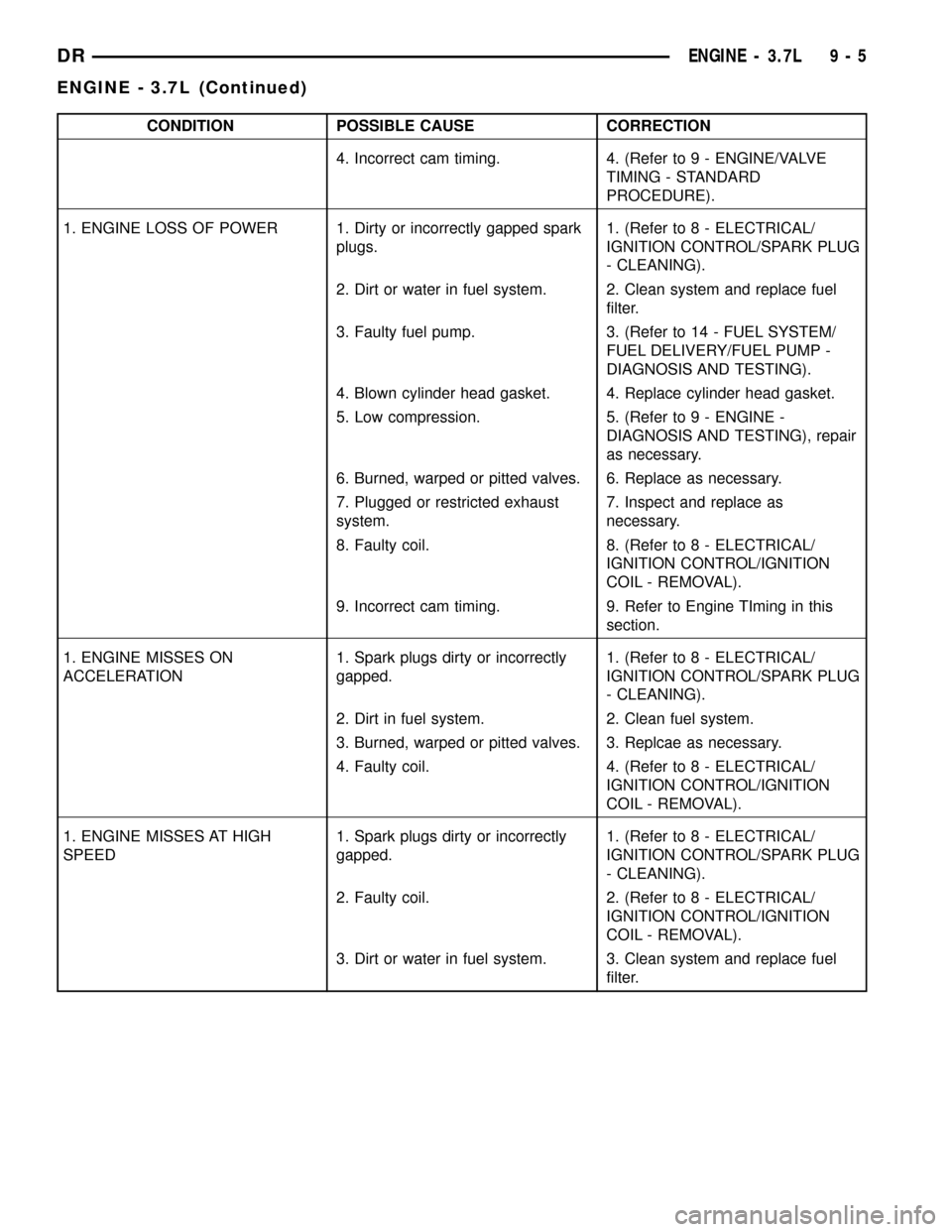
CONDITION POSSIBLE CAUSE CORRECTION
4. Incorrect cam timing. 4. (Refer to 9 - ENGINE/VALVE
TIMING - STANDARD
PROCEDURE).
1. ENGINE LOSS OF POWER 1. Dirty or incorrectly gapped spark
plugs.1. (Refer to 8 - ELECTRICAL/
IGNITION CONTROL/SPARK PLUG
- CLEANING).
2. Dirt or water in fuel system. 2. Clean system and replace fuel
filter.
3. Faulty fuel pump. 3. (Refer to 14 - FUEL SYSTEM/
FUEL DELIVERY/FUEL PUMP -
DIAGNOSIS AND TESTING).
4. Blown cylinder head gasket. 4. Replace cylinder head gasket.
5. Low compression. 5. (Refer to 9 - ENGINE -
DIAGNOSIS AND TESTING), repair
as necessary.
6. Burned, warped or pitted valves. 6. Replace as necessary.
7. Plugged or restricted exhaust
system.7. Inspect and replace as
necessary.
8. Faulty coil. 8. (Refer to 8 - ELECTRICAL/
IGNITION CONTROL/IGNITION
COIL - REMOVAL).
9. Incorrect cam timing. 9. Refer to Engine TIming in this
section.
1. ENGINE MISSES ON
ACCELERATION1. Spark plugs dirty or incorrectly
gapped.1. (Refer to 8 - ELECTRICAL/
IGNITION CONTROL/SPARK PLUG
- CLEANING).
2. Dirt in fuel system. 2. Clean fuel system.
3. Burned, warped or pitted valves. 3. Replcae as necessary.
4. Faulty coil. 4. (Refer to 8 - ELECTRICAL/
IGNITION CONTROL/IGNITION
COIL - REMOVAL).
1. ENGINE MISSES AT HIGH
SPEED1. Spark plugs dirty or incorrectly
gapped.1. (Refer to 8 - ELECTRICAL/
IGNITION CONTROL/SPARK PLUG
- CLEANING).
2. Faulty coil. 2. (Refer to 8 - ELECTRICAL/
IGNITION CONTROL/IGNITION
COIL - REMOVAL).
3. Dirt or water in fuel system. 3. Clean system and replace fuel
filter.
DRENGINE - 3.7L 9 - 5
ENGINE - 3.7L (Continued)
Page 1232 of 2627
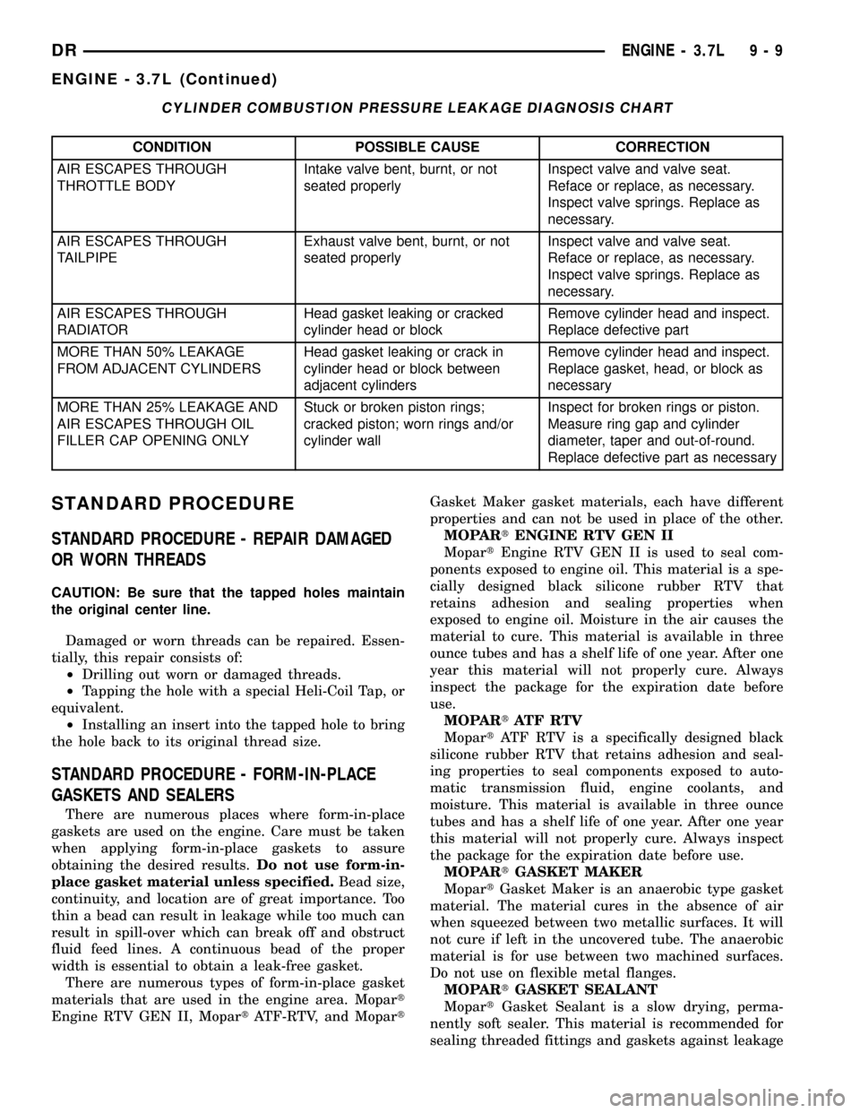
CYLINDER COMBUSTION PRESSURE LEAKAGE DIAGNOSIS CHART
CONDITION POSSIBLE CAUSE CORRECTION
AIR ESCAPES THROUGH
THROTTLE BODYIntake valve bent, burnt, or not
seated properlyInspect valve and valve seat.
Reface or replace, as necessary.
Inspect valve springs. Replace as
necessary.
AIR ESCAPES THROUGH
TAILPIPEExhaust valve bent, burnt, or not
seated properlyInspect valve and valve seat.
Reface or replace, as necessary.
Inspect valve springs. Replace as
necessary.
AIR ESCAPES THROUGH
RADIATORHead gasket leaking or cracked
cylinder head or blockRemove cylinder head and inspect.
Replace defective part
MORE THAN 50% LEAKAGE
FROM ADJACENT CYLINDERSHead gasket leaking or crack in
cylinder head or block between
adjacent cylindersRemove cylinder head and inspect.
Replace gasket, head, or block as
necessary
MORE THAN 25% LEAKAGE AND
AIR ESCAPES THROUGH OIL
FILLER CAP OPENING ONLYStuck or broken piston rings;
cracked piston; worn rings and/or
cylinder wallInspect for broken rings or piston.
Measure ring gap and cylinder
diameter, taper and out-of-round.
Replace defective part as necessary
STANDARD PROCEDURE
STANDARD PROCEDURE - REPAIR DAMAGED
OR WORN THREADS
CAUTION: Be sure that the tapped holes maintain
the original center line.
Damaged or worn threads can be repaired. Essen-
tially, this repair consists of:
²Drilling out worn or damaged threads.
²Tapping the hole with a special Heli-Coil Tap, or
equivalent.
²Installing an insert into the tapped hole to bring
the hole back to its original thread size.
STANDARD PROCEDURE - FORM-IN-PLACE
GASKETS AND SEALERS
There are numerous places where form-in-place
gaskets are used on the engine. Care must be taken
when applying form-in-place gaskets to assure
obtaining the desired results.Do not use form-in-
place gasket material unless specified.Bead size,
continuity, and location are of great importance. Too
thin a bead can result in leakage while too much can
result in spill-over which can break off and obstruct
fluid feed lines. A continuous bead of the proper
width is essential to obtain a leak-free gasket.
There are numerous types of form-in-place gasket
materials that are used in the engine area. Mopart
Engine RTV GEN II, MopartATF-RTV, and MopartGasket Maker gasket materials, each have different
properties and can not be used in place of the other.
MOPARtENGINE RTV GEN II
MopartEngine RTV GEN II is used to seal com-
ponents exposed to engine oil. This material is a spe-
cially designed black silicone rubber RTV that
retains adhesion and sealing properties when
exposed to engine oil. Moisture in the air causes the
material to cure. This material is available in three
ounce tubes and has a shelf life of one year. After one
year this material will not properly cure. Always
inspect the package for the expiration date before
use.
MOPARtATF RTV
MopartATF RTV is a specifically designed black
silicone rubber RTV that retains adhesion and seal-
ing properties to seal components exposed to auto-
matic transmission fluid, engine coolants, and
moisture. This material is available in three ounce
tubes and has a shelf life of one year. After one year
this material will not properly cure. Always inspect
the package for the expiration date before use.
MOPARtGASKET MAKER
MopartGasket Maker is an anaerobic type gasket
material. The material cures in the absence of air
when squeezed between two metallic surfaces. It will
not cure if left in the uncovered tube. The anaerobic
material is for use between two machined surfaces.
Do not use on flexible metal flanges.
MOPARtGASKET SEALANT
MopartGasket Sealant is a slow drying, perma-
nently soft sealer. This material is recommended for
sealing threaded fittings and gaskets against leakage
DRENGINE - 3.7L 9 - 9
ENGINE - 3.7L (Continued)
Page 1233 of 2627
of oil and coolant. Can be used on threaded and
machined parts under all temperatures. This mate-
rial is used on engines with multi-layer steel (MLS)
cylinder head gaskets. This material also will pre-
vent corrosion. MopartGasket Sealant is available in
a 13 oz. aerosol can or 4oz./16 oz. can w/applicator.
FORM-IN-PLACE GASKET AND SEALER
APPLICATION
Assembling parts using a form-in-place gasket
requires care but it's easier than using precut gas-
kets.
MopartGasket Maker material should be applied
sparingly 1 mm (0.040 in.) diameter or less of sealant
to one gasket surface. Be certain the material sur-
rounds each mounting hole. Excess material can eas-
ily be wiped off. Components should be torqued in
place within 15 minutes. The use of a locating dowel
is recommended during assembly to prevent smear-
ing material off the location.
MopartEngine RTV GEN II or ATF RTV gasket
material should be applied in a continuous bead
approximately 3 mm (0.120 in.) in diameter. All
mounting holes must be circled. For corner sealing, a
3.17 or 6.35 mm (1/8 or 1/4 in.) drop is placed in the
center of the gasket contact area. Uncured sealant
may be removed with a shop towel. Components
should be torqued in place while the sealant is still
wet to the touch (within 10 minutes). The usage of a
locating dowel is recommended during assembly to
prevent smearing material off the location.
MopartGasket Sealant in an aerosol can should be
applied using a thin, even coat sprayed completely
over both surfaces to be joined, and both sides of a
gasket. Then proceed with assembly. Material in a
can w/applicator can be brushed on evenly over the
sealing surfaces. Material in an aerosol can should be
used on engines with multi-layer steel gaskets.
STANDARD PROCEDURE - ENGINE GASKET
SURFACE PREPARATION
To ensure engine gasket sealing, proper surface
preparation must be performed, especially with the
use of aluminum engine components and multi-layer
steel cylinder head gaskets.
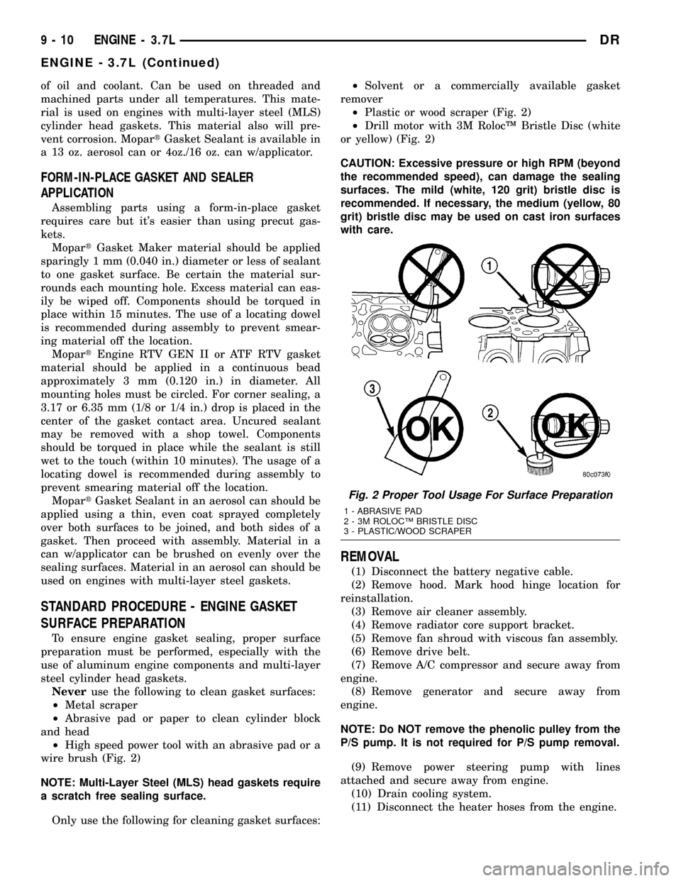
Neveruse the following to clean gasket surfaces:
²Metal scraper
²Abrasive pad or paper to clean cylinder block
and head
²High speed power tool with an abrasive pad or a
wire brush (Fig. 2)
NOTE: Multi-Layer Steel (MLS) head gaskets require
a scratch free sealing surface.
Only use the following for cleaning gasket surfaces:²Solvent or a commercially available gasket
remover
²Plastic or wood scraper (Fig. 2)
²Drill motor with 3M RolocŸ Bristle Disc (white
or yellow) (Fig. 2)
CAUTION: Excessive pressure or high RPM (beyond
the recommended speed), can damage the sealing
surfaces. The mild (white, 120 grit) bristle disc is
recommended. If necessary, the medium (yellow, 80
grit) bristle disc may be used on cast iron surfaces
with care.
REMOVAL
(1) Disconnect the battery negative cable.
(2) Remove hood. Mark hood hinge location for
reinstallation.
(3) Remove air cleaner assembly.
(4) Remove radiator core support bracket.
(5) Remove fan shroud with viscous fan assembly.
(6) Remove drive belt.
(7) Remove A/C compressor and secure away from
engine.
(8) Remove generator and secure away from
engine.
NOTE: Do NOT remove the phenolic pulley from the
P/S pump. It is not required for P/S pump removal.
(9) Remove power steering pump with lines
attached and secure away from engine.
(10) Drain cooling system.
(11) Disconnect the heater hoses from the engine.
Fig. 2 Proper Tool Usage For Surface Preparation
1 - ABRASIVE PAD
2 - 3M ROLOCŸ BRISTLE DISC
3 - PLASTIC/WOOD SCRAPER
9 - 10 ENGINE - 3.7LDR
ENGINE - 3.7L (Continued)
Page 1238 of 2627
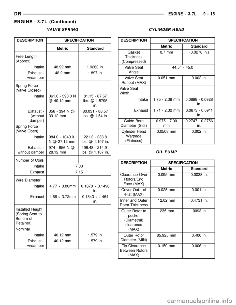
VALVE SPRING
DESCRIPTION SPECIFICATION
Metric Standard
Free Length
(Approx)
Intake 48.92 mm 1.9260 in.
Exhaust -
w/damper48.2 mm 1.897 in.
Spring Force
(Valve Closed)
Intake 361.0 - 390.0 N
@ 40.12 mm81.15 - 87.67
lbs. @ 1.5795
in.
Exhaust -
(without
damper)356-394N@
39.12 mm80.031 - 88.57
lbs. @ 1.54 in.
Spring Force
(Valve Open)
Intake 984.0 - 1040.0
N @ 27.12 mm221.2 - 233.8
lbs. @ 1.107 in.
Exhaust -
without damper974-956N@
28.12 mm196.48 - 214.91
lbs. @ 1.107 in.
Number of Coils
Intake 7.30
Exhaust 7.15
Wire Diameter
Intake 4.77 ý 3.80mm 0.1878 ý 0.1496
in.
Exhaust 4.66 ý 3.72mm 0.1843 ý .1464
in.
Installed Height
(Spring Seat to
Bottom of
Retainer)
Nominal
Intake 40.12 mm 1.579 in.
Exhaust -
w/damper40.12 mm 1.579 in.
CYLINDER HEAD
DESCRIPTION SPECIFICATION
Metric Standard
Gasket
Thickness
(Compressed)0.7 mm (0.0276 in.)
Valve Seat
Angle44.5É - 45.0É
Valve Seat
Runout (MAX)0.051 mm 0.002 in.
Valve Seat
Width
Intake 1.75 - 2.36 mm 0.0698 - 0.0928
in.
Exhaust 1.71 - 2.32 mm 0.0673 - 0.0911
in.
Guide Bore
Diameter (Std.)6.975 - 7.00
mm0.2747 - 0.2756
in.
Cylinder Head
Warpage
(Flatness)0.0508 mm 0.002 in.
OIL PUMP
DESCRIPTION SPECIFICATION
Metric Standard
Clearance Over
Rotors/End
Face (MAX)0.095 mm 0.0038 in.
Cover Out - of
-Flat (MAX)0.025 mm 0.001 in.
Inner and Outer
Rotor Thickness12.02 mm 0.4731 in.
Outer Rotor to
pocket
(Diametral)
clearance
(MAX).235 mm .0093 in.
Outer Rotor
Diameter (MIN)85.925 mm 0.400 in.
Tip Clearance
Between Rotors
(MAX)0.150 mm 0.006 in.
DRENGINE - 3.7L 9 - 15
ENGINE - 3.7L (Continued)
Page 1244 of 2627
AIR CLEANER ELEMENT
REMOVAL
Filter Element Only
Housing removal is not necessary for element (fil-
ter) replacement.
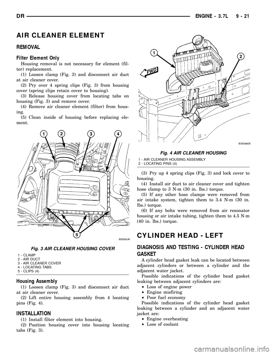
(1) Loosen clamp (Fig. 3) and disconnect air duct
at air cleaner cover.
(2) Pry over 4 spring clips (Fig. 3) from housing
cover (spring clips retain cover to housing).
(3) Release housing cover from locating tabs on
housing (Fig. 3) and remove cover.
(4) Remove air cleaner element (filter) from hous-
ing.
(5) Clean inside of housing before replacing ele-
ment.
Housing Assembly
(1) Loosen clamp (Fig. 3) and disconnect air duct
at air cleaner cover.
(2) Lift entire housing assembly from 4 locating
pins (Fig. 4).
INSTALLATION
(1) Install filter element into housing.
(2) Position housing cover into housing locating
tabs (Fig. 3).(3) Pry up 4 spring clips (Fig. 3) and lock cover to
housing.
(4) Install air duct to air cleaner cover and tighten
hose clamp to 3 N´m (30 in. lbs.) torque.
(5) If any other hose clamps were removed from
air intake system, tighten them to 3.4 N´m (30 in.
lbs.) torque.
(6) If any bolts were removed from air resonator
housing or air intake tubing, tighten them to 4.5 N´m
(40 in. lbs.) torque.
CYLINDER HEAD - LEFT
DIAGNOSIS AND TESTING - CYLINDER HEAD
GASKET
A cylinder head gasket leak can be located between
adjacent cylinders or between a cylinder and the
adjacent water jacket.
Possible indications of the cylinder head gasket
leaking between adjacent cylinders are:
²Loss of engine power
²Engine misfiring
²Poor fuel economy
Possible indications of the cylinder head gasket
leaking between a cylinder and an adjacent water
jacket are:
²Engine overheating
²Loss of coolant
Fig. 3 AIR CLEANER HOUSING COVER
1 - CLAMP
2 - AIR DUCT
3 - AIR CLEANER COVER
4 - LOCATING TABS
5 - CLIPS (4)
Fig. 4 AIR CLEANER HOUSING
1 - AIR CLEANER HOUSING ASSEMBLY
2 - LOCATING PINS (4)
DRENGINE - 3.7L 9 - 21
Page 1245 of 2627

²Excessive steam (white smoke) emitting from
exhaust
²Coolant foaming
CYLINDER-TO-CYLINDER LEAKAGE TEST
To determine if an engine cylinder head gasket is
leaking between adjacent cylinders, follow the proce-
dures in Cylinder Compression Pressure Test (Refer
to 9 - ENGINE - DIAGNOSIS AND TESTING). An
engine cylinder head gasket leaking between adja-
cent cylinders will result in approximately a 50 - 70%
reduction in compression pressure.
CYLINDER-TO-WATER JACKET LEAKAGE TEST
WARNING: USE EXTREME CAUTION WHEN THE
ENGINE IS OPERATING WITH COOLANT PRES-
SURE CAP REMOVED.
VISUAL TEST METHOD
With the engine cool, remove the coolant pressure
cap. Start the engine and allow it to warm up until
thermostat opens.
If a large combustion/compression pressure leak
exists, bubbles will be visible in the coolant.
COOLING SYSTEM TESTER METHOD
WARNING: WITH COOLING SYSTEM TESTER IN
PLACE, PRESSURE WILL BUILD UP FAST. EXCES-
SIVE PRESSURE BUILT UP, BY CONTINUOUS
ENGINE OPERATION, MUST BE RELEASED TO A
SAFE PRESSURE POINT. NEVER PERMIT PRES-
SURE TO EXCEED 138 kPa (20 psi).
Install Cooling System Tester 7700 or equivalent to
pressure cap neck. Start the engine and observe the
tester's pressure gauge. If gauge pulsates with every
power stroke of a cylinder a combustion pressure
leak is evident.
CHEMICAL TEST METHOD
Combustion leaks into the cooling system can also
be checked by using Bloc-Chek Kit C-3685-A or
equivalent. Perform test following the procedures
supplied with the tool kit.
REMOVAL
(1) Disconnect the negative cable from the battery.
(2) Raise the vehicle on a hoist.
(3) Disconnect the exhaust pipe at the left side
exhaust manifold.
(4) Drain the engine coolant(Refer to 7 - COOL-
ING - STANDARD PROCEDURE).
(5) Lower the vehicle.(6) Remove the intake manifold(Refer to 9 -
ENGINE/MANIFOLDS/INTAKE MANIFOLD -
REMOVAL).
(7) Remove the master cylinder and booster assem-
bly(Refer to 5 - BRAKES/HYDRAULIC/MECHANI-
CAL/POWER BRAKE BOOSTER - REMOVAL).
(8) Remove the cylinder head cover(Refer to 9 -
ENGINE/CYLINDER HEAD/CYLINDER HEAD
COVER(S) - REMOVAL).
(9) Remove the fan shroud and fan blade assem-
bly(Refer to 7 - COOLING/ENGINE/RADIATOR FAN
- REMOVAL).
(10) Remove accessory drive belt(Refer to 7 -
COOLING/ACCESSORY DRIVE/DRIVE BELTS -
REMOVAL).
(11) Remove the power steering pump and set
aside.
(12) Rotate the crankshaft until the damper tim-
ing mark is aligned with TDC indicator mark (Fig.
5).
(13) Verify the V6 mark on the camshaft sprocket
is at the 12 o'clock position (Fig. 6). Rotate the crank-
shaft one turn if necessary.
(14) Remove the crankshaft damper(Refer to 9 -
ENGINE/ENGINE BLOCK/VIBRATION DAMPER -
REMOVAL).
(15) Remove the timing chain cover(Refer to 9 -
ENGINE/VALVE TIMING/TIMING BELT / CHAIN
COVER(S) - REMOVAL).
Fig. 5 Engine Top Dead Center
1 - TIMING CHAIN COVER
2 - CRANKSHAFT TIMING MARKS
9 - 22 ENGINE - 3.7LDR
CYLINDER HEAD - LEFT (Continued)
Page 1247 of 2627
(20) Remove the left side secondary chain
guide(Refer to 9 - ENGINE/VALVE TIMING/TIMING
BELT/CHAIN AND SPROCKETS - REMOVAL).
(21) Remove the retaining bolt and the camshaft
drive gear.
CAUTION: Do not allow the engine to rotate. Severe
damage to the valve train can occur.
CAUTION: Do not overlook the four smaller bolts at
the front of the cylinder head. Do not attempt to
remove the cylinder head without removing these
four bolts.
NOTE: The cylinder head is attached to the cylinder
block with twelve bolts.
(22) Remove the cylinder head retaining bolts.
(23) Remove the cylinder head and gasket. Discard
the gasket.
CAUTION: Do not lay the cylinder head on its gas-
ket sealing surface, due to the design of the cylin-
der head gasket any distortion to the cylinder head
sealing surface may prevent the gasket from prop-
erly sealing resulting in leaks.
INSTALLATION
NOTE: The cylinder head bolts are tightened using
a torque plus angle procedure. The bolts must be
examined BEFORE reuse. If the threads are necked
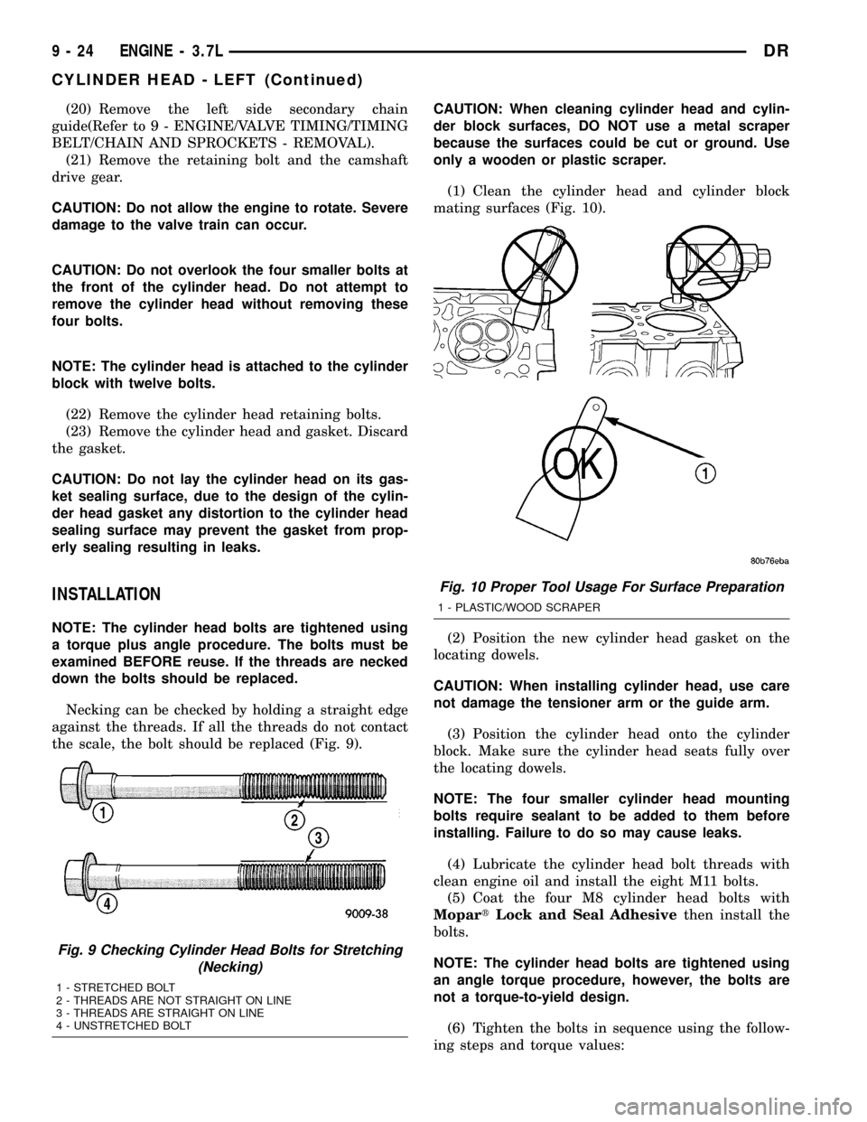
down the bolts should be replaced.
Necking can be checked by holding a straight edge
against the threads. If all the threads do not contact
the scale, the bolt should be replaced (Fig. 9).CAUTION: When cleaning cylinder head and cylin-
der block surfaces, DO NOT use a metal scraper
because the surfaces could be cut or ground. Use
only a wooden or plastic scraper.
(1) Clean the cylinder head and cylinder block
mating surfaces (Fig. 10).
(2) Position the new cylinder head gasket on the
locating dowels.
CAUTION: When installing cylinder head, use care
not damage the tensioner arm or the guide arm.
(3) Position the cylinder head onto the cylinder
block. Make sure the cylinder head seats fully over
the locating dowels.
NOTE: The four smaller cylinder head mounting
bolts require sealant to be added to them before
installing. Failure to do so may cause leaks.
(4) Lubricate the cylinder head bolt threads with
clean engine oil and install the eight M11 bolts.
(5) Coat the four M8 cylinder head bolts with
MopartLock and Seal Adhesivethen install the
bolts.
NOTE: The cylinder head bolts are tightened using
an angle torque procedure, however, the bolts are
not a torque-to-yield design.
(6) Tighten the bolts in sequence using the follow-
ing steps and torque values:
Fig. 9 Checking Cylinder Head Bolts for Stretching
(Necking)
1 - STRETCHED BOLT
2 - THREADS ARE NOT STRAIGHT ON LINE
3 - THREADS ARE STRAIGHT ON LINE
4 - UNSTRETCHED BOLT
Fig. 10 Proper Tool Usage For Surface Preparation
1 - PLASTIC/WOOD SCRAPER
9 - 24 ENGINE - 3.7LDR
CYLINDER HEAD - LEFT (Continued)
Page 1251 of 2627
REMOVAL
(1) Disconnect negative cable from battery.
(2)
Remove the resonator assemble and air inlet hose.
(3) Disconnect injector connectors and un-clip the
injector harness.
(4) Route injector harness in front of cylinder head
cover.
(5) Disconnect the left side breather tube and
remove the breather tube.
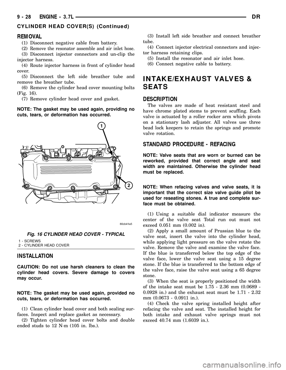
(6) Remove the cylinder head cover mounting bolts
(Fig. 16).
(7) Remove cylinder head cover and gasket.
NOTE: The gasket may be used again, providing no
cuts, tears, or deformation has occurred.
INSTALLATION
CAUTION: Do not use harsh cleaners to clean the
cylinder head covers. Severe damage to covers
may occur.
NOTE: The gasket may be used again, provided no
cuts, tears, or deformation has occurred.
(1) Clean cylinder head cover and both sealing sur-
faces. Inspect and replace gasket as necessary.
(2) Tighten cylinder head cover bolts and double
ended studs to 12 N´m (105 in. lbs.).(3) Install left side breather and connect breather
tube.
(4) Connect injector electrical connectors and injec-
tor harness retaining clips.
(5) Install the resonator and air inlet hose.
(6) Connect negative cable to battery.
INTAKE/EXHAUST VALVES &
SEATS
DESCRIPTION
The valves are made of heat resistant steel and
have chrome plated stems to prevent scuffing. Each
valve is actuated by a roller rocker arm which pivots
on a stationary lash adjuster. All valves use three
bead lock keepers to retain the springs and promote
valve rotation.
STANDARD PROCEDURE - REFACING
NOTE: Valve seats that are worn or burned can be
reworked, provided that correct angle and seat
width are maintained. Otherwise the cylinder head
must be replaced.
NOTE: When refacing valves and valve seats, it is
important that the correct size valve guide pilot be
used for reseating stones. A true and complete sur-
face must be obtained.
(1) Using a suitable dial indicator measure the
center of the valve seat Total run out must not
exceed 0.051 mm (0.002 in).
(2) Apply a small amount of Prussian blue to the
valve seat, insert the valve into the cylinder head,
while applying light pressure on the valve rotate the
valve. Remove the valve and examine the valve face.
If the blue is transferred below the top edge of the
valve face, lower the valve seat using a 15 degree
stone. If the blue is transferred to the bottom edge of
the valve face, raise the valve seat using a 65 degree
stone.
(3) When the seat is properly positioned the width
of the intake seat must be 1.75 - 2.36 mm (0.0689 -
0.0928 in.) and the exhaust seat must be 1.71 - 2.32
mm (0.0673 - 0.0911 in.).
(4) Check the valve spring installed height after
refacing the valve and seat. The installed height for
both intake and exhaust valve springs must not
exceed 40.74 mm (1.6039 in.).
Fig. 16 CYLINDER HEAD COVER - TYPICAL
1 - SCREWS
2 - CYLINDER HEAD COVER
9 - 28 ENGINE - 3.7LDR
CYLINDER HEAD COVER(S) (Continued)