1998 DODGE RAM 1500 oil
[x] Cancel search: oilPage 1467 of 2627
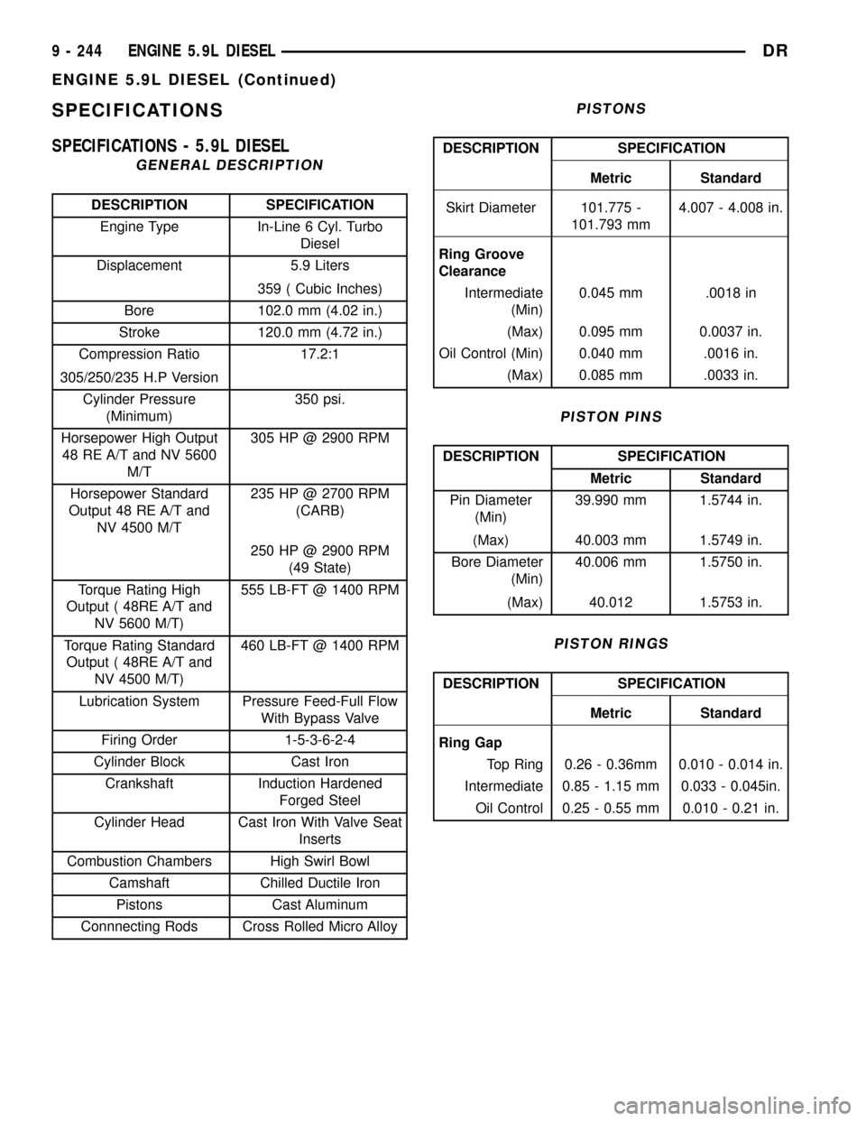
SPECIFICATIONS
SPECIFICATIONS - 5.9L DIESEL
GENERAL DESCRIPTION
DESCRIPTION SPECIFICATION
Engine Type In-Line 6 Cyl. Turbo
Diesel
Displacement 5.9 Liters
359 ( Cubic Inches)
Bore 102.0 mm (4.02 in.)
Stroke 120.0 mm (4.72 in.)
Compression Ratio 17.2:1
305/250/235 H.P Version
Cylinder Pressure
(Minimum)350 psi.
Horsepower High Output
48 RE A/T and NV 5600
M/T305 HP @ 2900 RPM
Horsepower Standard
Output 48 RE A/T and
NV 4500 M/T235 HP @ 2700 RPM
(CARB)
250 HP @ 2900 RPM
(49 State)
Torque Rating High
Output ( 48RE A/T and
NV 5600 M/T)555 LB-FT @ 1400 RPM
Torque Rating Standard
Output ( 48RE A/T and
NV 4500 M/T)460 LB-FT @ 1400 RPM
Lubrication System Pressure Feed-Full Flow
With Bypass Valve
Firing Order 1-5-3-6-2-4
Cylinder Block Cast Iron
Crankshaft Induction Hardened
Forged Steel
Cylinder Head Cast Iron With Valve Seat
Inserts
Combustion Chambers High Swirl Bowl
Camshaft Chilled Ductile Iron
Pistons Cast Aluminum
Connnecting Rods Cross Rolled Micro Alloy
PISTONS
DESCRIPTION SPECIFICATION
Metric Standard
Skirt Diameter 101.775 -
101.793 mm4.007 - 4.008 in.
Ring Groove
Clearance
Intermediate
(Min)0.045 mm .0018 in
(Max) 0.095 mm 0.0037 in.
Oil Control (Min) 0.040 mm .0016 in.
(Max) 0.085 mm .0033 in.
PISTON PINS
DESCRIPTION SPECIFICATION
Metric Standard
Pin Diameter
(Min)39.990 mm 1.5744 in.
(Max) 40.003 mm 1.5749 in.
Bore Diameter
(Min)40.006 mm 1.5750 in.
(Max) 40.012 1.5753 in.
PISTON RINGS
DESCRIPTION SPECIFICATION
Metric Standard
Ring Gap
Top Ring 0.26 - 0.36mm 0.010 - 0.014 in.
Intermediate 0.85 - 1.15 mm 0.033 - 0.045in.
Oil Control 0.25 - 0.55 mm 0.010 - 0.21 in.
9 - 244 ENGINE 5.9L DIESELDR
ENGINE 5.9L DIESEL (Continued)
Page 1468 of 2627
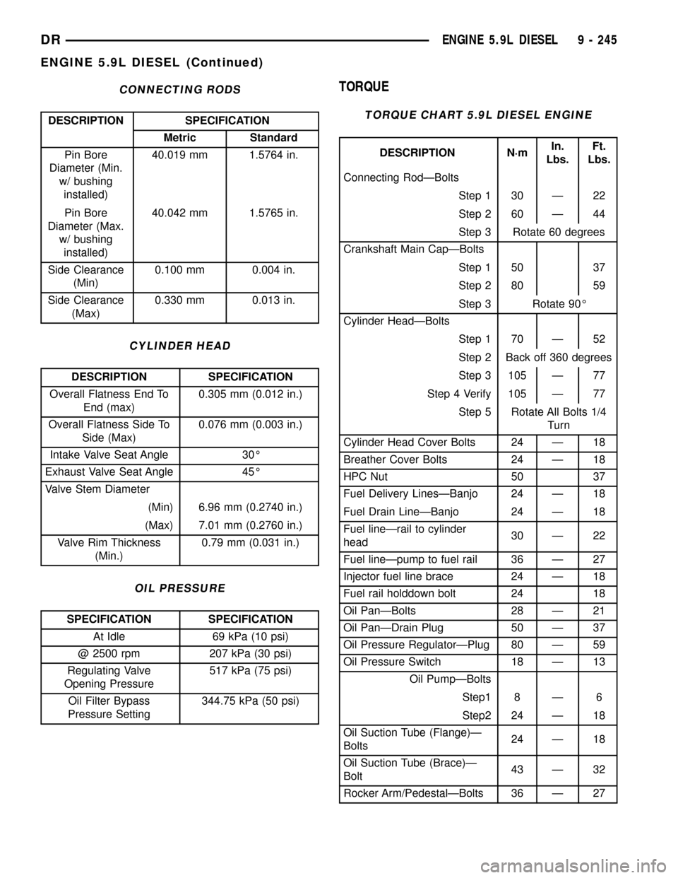
CONNECTING RODS
DESCRIPTION SPECIFICATION
Metric Standard
Pin Bore
Diameter (Min.
w/ bushing
installed)40.019 mm 1.5764 in.
Pin Bore
Diameter (Max.
w/ bushing
installed)40.042 mm 1.5765 in.
Side Clearance
(Min)0.100 mm 0.004 in.
Side Clearance
(Max)0.330 mm 0.013 in.
CYLINDER HEAD
DESCRIPTION SPECIFICATION
Overall Flatness End To
End (max)0.305 mm (0.012 in.)
Overall Flatness Side To
Side (Max)0.076 mm (0.003 in.)
Intake Valve Seat Angle 30É
Exhaust Valve Seat Angle 45É
Valve Stem Diameter
(Min) 6.96 mm (0.2740 in.)
(Max) 7.01 mm (0.2760 in.)
Valve Rim Thickness
(Min.)0.79 mm (0.031 in.)
OIL PRESSURE
SPECIFICATION SPECIFICATION
At Idle 69 kPa (10 psi)
@ 2500 rpm 207 kPa (30 psi)
Regulating Valve
Opening Pressure517 kPa (75 psi)
Oil Filter Bypass
Pressure Setting344.75 kPa (50 psi)
TORQUE
TORQUE CHART 5.9L DIESEL ENGINE
DESCRIPTION N´mIn.
Lbs.Ft.
Lbs.
Connecting RodÐBolts
Step 1 30 Ð 22
Step 2 60 Ð 44
Step 3 Rotate 60 degrees
Crankshaft Main CapÐBolts
Step 1 50 37
Step 2 80 59
Step 3 Rotate 90É
Cylinder HeadÐBolts
Step 1 70 Ð 52
Step 2 Back off 360 degrees
Step 3 105 Ð 77
Step 4 Verify 105 Ð 77
Step 5 Rotate All Bolts 1/4
Turn
Cylinder Head Cover Bolts 24 Ð 18
Breather Cover Bolts 24 Ð 18
HPC Nut 50 37
Fuel Delivery LinesÐBanjo 24 Ð 18
Fuel Drain LineÐBanjo 24 Ð 18
Fuel lineÐrail to cylinder
head30 Ð 22
Fuel lineÐpump to fuel rail 36 Ð 27
Injector fuel line brace 24 Ð 18
Fuel rail holddown bolt 24 18
Oil PanÐBolts 28 Ð 21
Oil PanÐDrain Plug 50 Ð 37
Oil Pressure RegulatorÐPlug 80 Ð 59
Oil Pressure Switch 18 Ð 13
Oil PumpÐBolts
Step1 8 Ð 6
Step2 24 Ð 18
Oil Suction Tube (Flange)Ð
Bolts24 Ð 18
Oil Suction Tube (Brace)Ð
Bolt43 Ð 32
Rocker Arm/PedestalÐBolts 36 Ð 27
DRENGINE 5.9L DIESEL 9 - 245
ENGINE 5.9L DIESEL (Continued)
Page 1469 of 2627
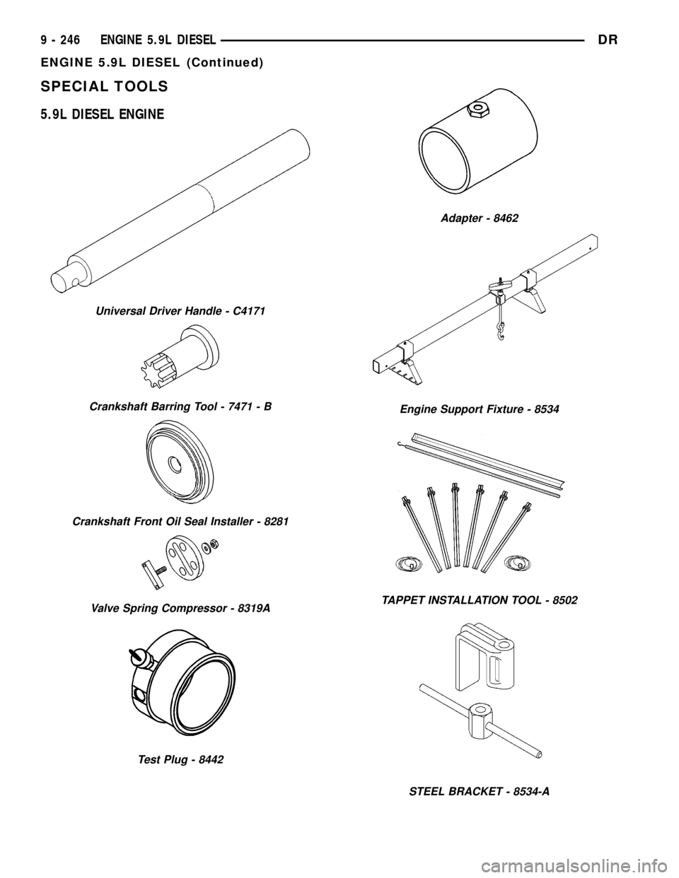
SPECIAL TOOLS
5.9L DIESEL ENGINE
Universal Driver Handle - C4171
Crankshaft Barring Tool - 7471 - B
Crankshaft Front Oil Seal Installer - 8281
Valve Spring Compressor - 8319A
Test Plug - 8442
Adapter - 8462
Engine Support Fixture - 8534
TAPPET INSTALLATION TOOL - 8502
STEEL BRACKET - 8534-A
9 - 246 ENGINE 5.9L DIESELDR
ENGINE 5.9L DIESEL (Continued)
Page 1471 of 2627
ENGINE DATA PLATE
DESCRIPTION
The engine data plate contains specific information
that is helpful to servicing and obtaining parts for
the engine. The data plate can be found affixed to the
breather cover on the left side of the engine. Informa-
tion that can be found on the data plate includes:
²Date of Engine Manufacture
²Engine Serial Number
²Control Parts List (CPL)
²Engine Rated Horsepower
²Engine Firing Order
²Engine Displacement
²Valve Lash Reset Specifications
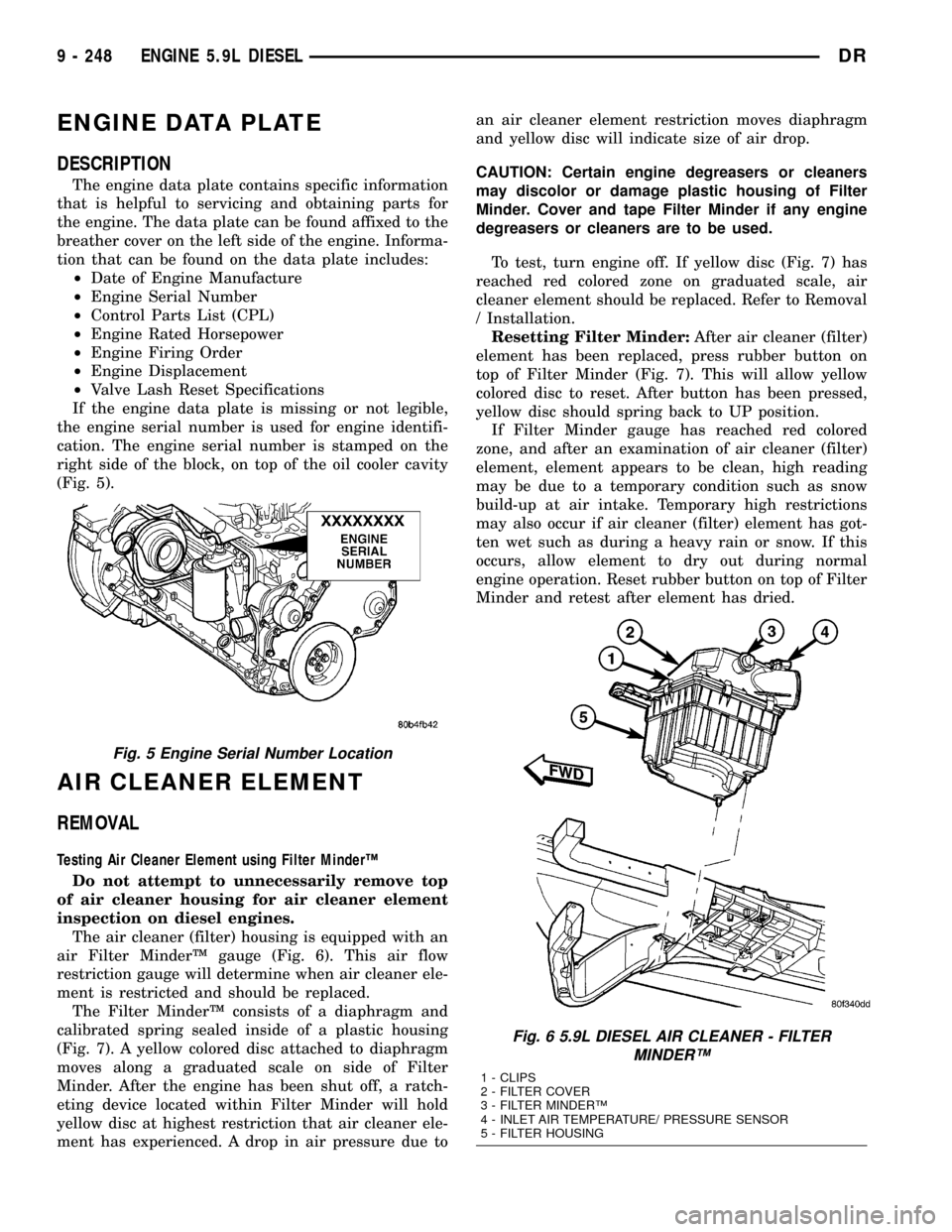
If the engine data plate is missing or not legible,
the engine serial number is used for engine identifi-
cation. The engine serial number is stamped on the
right side of the block, on top of the oil cooler cavity
(Fig. 5).
AIR CLEANER ELEMENT
REMOVAL
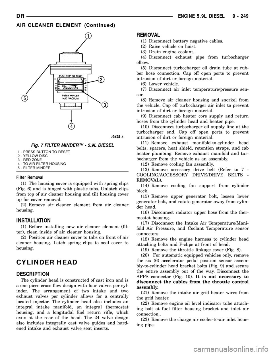
Testing Air Cleaner Element using Filter MinderŸ
Do not attempt to unnecessarily remove top
of air cleaner housing for air cleaner element
inspection on diesel engines.
The air cleaner (filter) housing is equipped with an
air Filter MinderŸ gauge (Fig. 6). This air flow
restriction gauge will determine when air cleaner ele-
ment is restricted and should be replaced.
The Filter MinderŸ consists of a diaphragm and
calibrated spring sealed inside of a plastic housing
(Fig. 7). A yellow colored disc attached to diaphragm
moves along a graduated scale on side of Filter
Minder. After the engine has been shut off, a ratch-
eting device located within Filter Minder will hold
yellow disc at highest restriction that air cleaner ele-
ment has experienced. A drop in air pressure due toan air cleaner element restriction moves diaphragm
and yellow disc will indicate size of air drop.
CAUTION: Certain engine degreasers or cleaners
may discolor or damage plastic housing of Filter
Minder. Cover and tape Filter Minder if any engine
degreasers or cleaners are to be used.
To test, turn engine off. If yellow disc (Fig. 7) has
reached red colored zone on graduated scale, air
cleaner element should be replaced. Refer to Removal
/ Installation.
Resetting Filter Minder:After air cleaner (filter)
element has been replaced, press rubber button on
top of Filter Minder (Fig. 7). This will allow yellow
colored disc to reset. After button has been pressed,
yellow disc should spring back to UP position.
If Filter Minder gauge has reached red colored
zone, and after an examination of air cleaner (filter)
element, element appears to be clean, high reading
may be due to a temporary condition such as snow
build-up at air intake. Temporary high restrictions
may also occur if air cleaner (filter) element has got-
ten wet such as during a heavy rain or snow. If this
occurs, allow element to dry out during normal
engine operation. Reset rubber button on top of Filter
Minder and retest after element has dried.
Fig. 5 Engine Serial Number Location
Fig. 6 5.9L DIESEL AIR CLEANER - FILTER
MINDERŸ
1 - CLIPS
2 - FILTER COVER
3 - FILTER MINDERŸ
4 - INLET AIR TEMPERATURE/ PRESSURE SENSOR
5 - FILTER HOUSING
9 - 248 ENGINE 5.9L DIESELDR
Page 1472 of 2627
Filter Removal
(1) The housing cover is equipped with spring clips
(Fig. 6) and is hinged with plastic tabs. Unlatch clips
from top of air cleaner housing and tilt housing cover
up for cover removal.
(2) Remove air cleaner element from air cleaner
housing.
INSTALLATION
(1) Before installing new air cleaner element (fil-
ter), clean inside of air cleaner housing.
(2) Position air cleaner cover to tabs on front of air
cleaner housing. Latch spring clips to seal cover to
housing.
CYLINDER HEAD
DESCRIPTION
The cylinder head is constructed of cast iron and is
a one piece cross flow design with four valves per cyl-
inder. The arrangement of two intake and two
exhaust valves per cylinder allows for a centrally
located injector. The cylinder head also includes an
integral intake manifold, an integral thermostat
housing, and a longitudal fuel return rifle, which
exits at the rear of the head. The 24 valve design
also includes integrally cast valve guides and hard-
ened intake and exhaust valve seat inserts.
REMOVAL
(1) Disconnect battery negative cables.
(2) Raise vehicle on hoist.
(3) Drain engine coolant.
(4) Disconnect exhaust pipe from turbocharger
elbow.
(5) Disconnect turbocharger oil drain tube at rub-
ber hose connection. Cap off open ports to prevent
intrusion of dirt or foreign material.
(6) Lower vehicle.
(7) Disconnect air inlet temperature/pressure sen-
sor.
(8) Remove air cleaner housing and snorkel from
the vehicle. Cap off turbocharger air inlet to prevent
intrusion of dirt or foreign material.
(9) Disconnect cab heater core supply and return
hoses from the cylinder head and heater pipe.
(10) Disconnect turbocharger oil supply line at the
turbocharger end. Cap off open ports to prevent
intrusion of dirt or foreign material.
(11) Remove exhaust manifold-to-cylinder head
bolts, spacers, heat shield, retention straps, and cab
heater plumbing. Remove exhaust manifold and tur-
bocharger from the vehicle as an assembly.
(12) Remove cooling fan assembly.
(13) Remove accessory drive belt (Refer to 7 -
COOLING/ACCESSORY DRIVE/DRIVE BELTS -
REMOVAL).
(14) Remove cooling fan support from cylinder
block.
(15) Remove upper generator bolt, loosen lower
generator bolt, and rotate generator away from cylin-
der head.
(16) Disconnect radiator upper hose from the ther-
mostat housing.
(17) Disconnect the Intake Air Temperature/Mani-
fold Air Pressure, and Coolant Temperature sensor
connectors.
(18) Remove the engine harness to cylinder head
attaching bolts and P-clips at front of head.
(19) Remove the throttle linkage cover (Fig. 8).
(20) For automatic equipped vehicles only, remove
the six (6) accelerator pedal position sensor assem-
bly-to-cylinder head bracket bolts (Fig. 9) and secure
the entire assembly out of the way. Disconnect the
APPS connector (Fig. 10).It is not necessary to
disconnect the cables from the throttle control
assembly.
(21) Remove the intake air grid heater wires from
the grid heater.
(22) Remove engine oil level indicator tube attach-
ing bolt at fuel filter housing bracket and inlet air
connection..
(23) Remove the charge air cooler-to-air inlet hous-
ing pipe.
Fig. 7 FILTER MINDERŸ - 5.9L DIESEL
1 - PRESS BUTTON TO RESET
2 - YELLOW DISC
3 - RED ZONE
4 - TO AIR FILTER HOUSING
5 - FILTER MINDER
DRENGINE 5.9L DIESEL 9 - 249
AIR CLEANER ELEMENT (Continued)
Page 1476 of 2627
INSPECTIONÐPUSHRODS
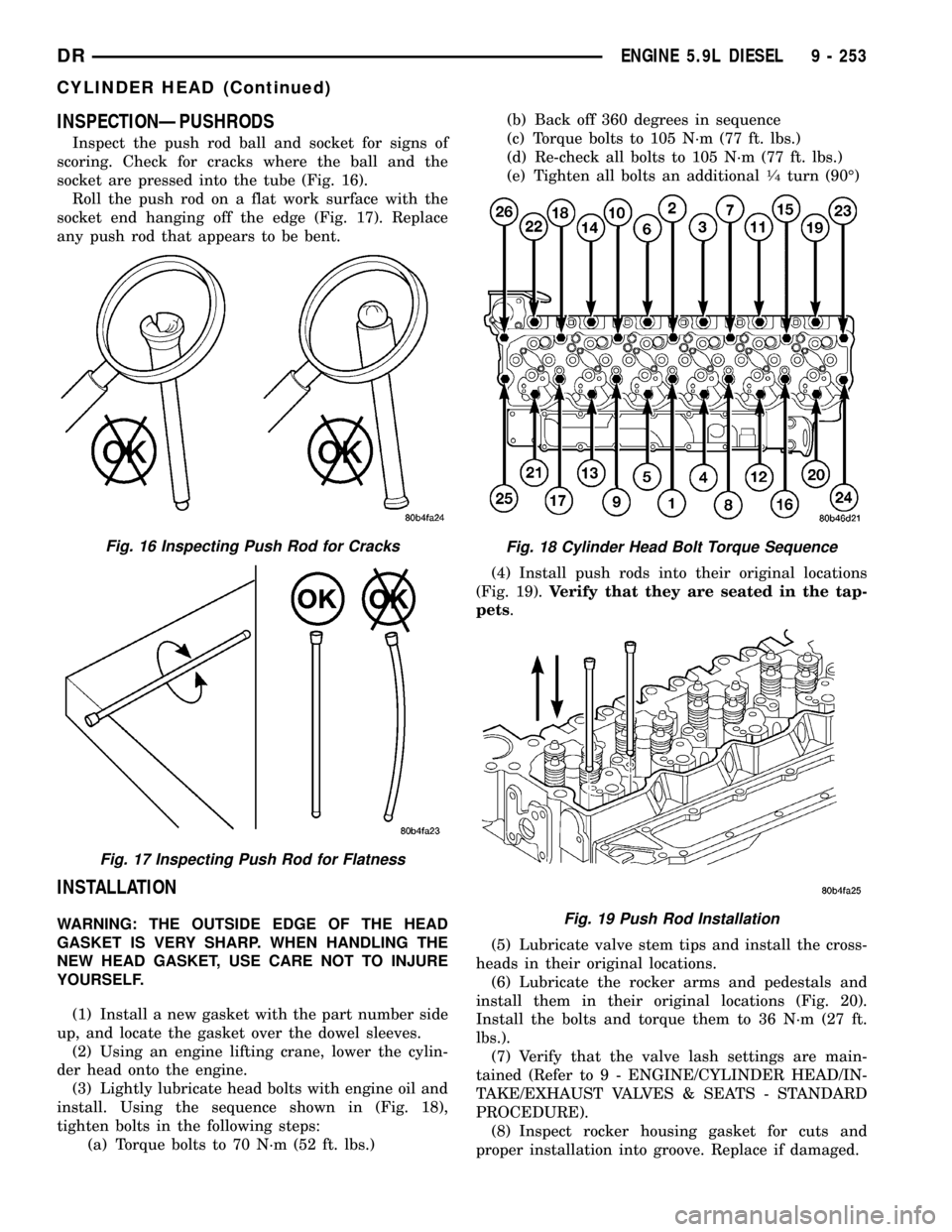
Inspect the push rod ball and socket for signs of
scoring. Check for cracks where the ball and the
socket are pressed into the tube (Fig. 16).
Roll the push rod on a flat work surface with the
socket end hanging off the edge (Fig. 17). Replace
any push rod that appears to be bent.
INSTALLATION
WARNING: THE OUTSIDE EDGE OF THE HEAD
GASKET IS VERY SHARP. WHEN HANDLING THE
NEW HEAD GASKET, USE CARE NOT TO INJURE
YOURSELF.
(1) Install a new gasket with the part number side
up, and locate the gasket over the dowel sleeves.
(2) Using an engine lifting crane, lower the cylin-
der head onto the engine.
(3) Lightly lubricate head bolts with engine oil and
install. Using the sequence shown in (Fig. 18),
tighten bolts in the following steps:
(a) Torque bolts to 70 N´m (52 ft. lbs.)(b) Back off 360 degrees in sequence
(c) Torque bolts to 105 N´m (77 ft. lbs.)
(d) Re-check all bolts to 105 N´m (77 ft. lbs.)
(e) Tighten all bolts an additional
1¤4turn (90É)
(4) Install push rods into their original locations
(Fig. 19).Verify that they are seated in the tap-
pets.
(5) Lubricate valve stem tips and install the cross-
heads in their original locations.
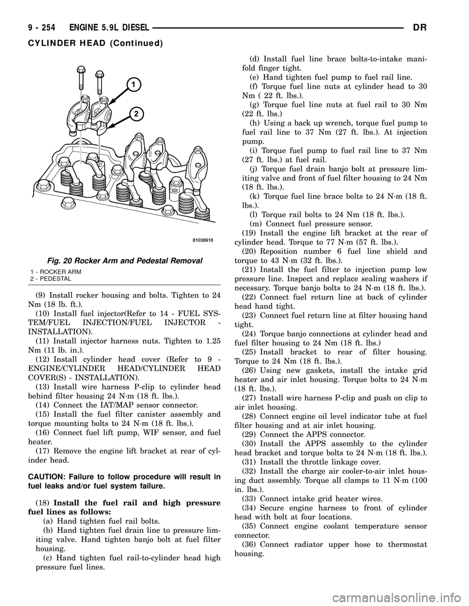
(6) Lubricate the rocker arms and pedestals and
install them in their original locations (Fig. 20).
Install the bolts and torque them to 36 N´m (27 ft.
lbs.).
(7) Verify that the valve lash settings are main-
tained (Refer to 9 - ENGINE/CYLINDER HEAD/IN-
TAKE/EXHAUST VALVES & SEATS - STANDARD
PROCEDURE).
(8) Inspect rocker housing gasket for cuts and
proper installation into groove. Replace if damaged.
Fig. 16 Inspecting Push Rod for Cracks
Fig. 17 Inspecting Push Rod for Flatness
Fig. 18 Cylinder Head Bolt Torque Sequence
Fig. 19 Push Rod Installation
DRENGINE 5.9L DIESEL 9 - 253
CYLINDER HEAD (Continued)
Page 1477 of 2627
(9) Install rocker housing and bolts. Tighten to 24
Nm (18 lb. ft.).
(10) Install fuel injector(Refer to 14 - FUEL SYS-
TEM/FUEL INJECTION/FUEL INJECTOR -
INSTALLATION).
(11) Install injector harness nuts. Tighten to 1.25
Nm (11 lb. in.).
(12) Install cylinder head cover (Refer to 9 -
ENGINE/CYLINDER HEAD/CYLINDER HEAD
COVER(S) - INSTALLATION).
(13) Install wire harness P-clip to cylinder head
behind filter housing 24 N´m (18 ft. lbs.).
(14) Connect the IAT/MAP sensor connector.
(15) Install the fuel filter canister assembly and
torque mounting bolts to 24 N´m (18 ft. lbs.).
(16) Connect fuel lift pump, WIF sensor, and fuel
heater.
(17) Remove the engine lift bracket at rear of cyl-
inder head.
CAUTION: Failure to follow procedure will result in
fuel leaks and/or fuel system failure.
(18)Install the fuel rail and high pressure
fuel lines as follows:
(a) Hand tighten fuel rail bolts.
(b) Hand tighten fuel drain line to pressure lim-
iting valve. Hand tighten banjo bolt at fuel filter
housing.
(c) Hand tighten fuel rail-to-cylinder head high
pressure fuel lines.(d) Install fuel line brace bolts-to-intake mani-
fold finger tight.
(e) Hand tighten fuel pump to fuel rail line.
(f) Torque fuel line nuts at cylinder head to 30
Nm ( 22 ft. lbs.).
(g) Torque fuel line nuts at fuel rail to 30 Nm
(22 ft. lbs.)
(h) Using a back up wrench, torque fuel pump to
fuel rail line to 37 Nm (27 ft. lbs.). At injection
pump.
(i) Torque fuel pump to fuel rail line to 37 Nm
(27 ft. lbs.) at fuel rail.
(j) Torque fuel drain banjo bolt at pressure lim-
iting valve and front of fuel filter housing to 24 Nm
(18 ft. lbs.).
(k) Torque fuel line brace bolts to 24 N´m (18 ft.
lbs.).
(l) Torque rail bolts to 24 Nm (18 ft. lbs.).
(m) Connect fuel pressure sensor.
(19) Install the engine lift bracket at the rear of
cylinder head. Torque to 77 N´m (57 ft. lbs.).
(20) Reposition number 6 fuel line shield and
torque to 43 N´m (32 ft. lbs.).
(21) Install the fuel filter to injection pump low
pressure line. Inspect and replace sealing washers if
necessary. Torque banjo bolts to 24 N´m (18 ft. lbs.).
(22) Connect fuel return line at back of cylinder
head hand tight.
(23) Connect fuel return line at filter housing hand
tight.
(24) Torque banjo connections at cylinder head and
fuel filter housing to 24 Nm (18 ft. lbs.)
(25) Install bracket to rear of filter housing.
Torque to 24 Nm (18 ft. lbs.).
(26) Using new gaskets, install the intake grid
heater and air inlet housing. Torque bolts to 24 N´m
(18 ft. lbs.).
(27) Install wire harness P-clip and push on clip to
air inlet housing.
(28) Connect engine oil level indicator tube at fuel
filter housing and at air inlet housing.
(29) Connect the APPS connector.
(30) Install the APPS assembly to the cylinder
head bracket and torque bolts to 24 N´m (18 ft. lbs.).
(31) Install the throttle linkage cover.
(32) Install the charge air cooler-to-air inlet hous-
ing duct assembly. Torque all clamps to 11 N´m (100
in. lbs.).
(33) Connect intake grid heater wires.
(34) Secure engine harness to front of cylinder
head with bolt at four locations.
(35) Connect engine coolant temperature sensor
connector.
(36) Connect radiator upper hose to thermostat
housing.
Fig. 20 Rocker Arm and Pedestal Removal
1 - ROCKER ARM
2 - PEDESTAL
9 - 254 ENGINE 5.9L DIESELDR
CYLINDER HEAD (Continued)
Page 1478 of 2627
(37) Rotate generator into position. Install upper
bolt and torque upper and lower bolts.
(38)
Install wire harness push-on clip below bracket.
(39) Install wire harness P-clip to top of bracket.
(40) Install fan support and torque to 32 N´m (24
ft. lbs.).
(41) Install cooling fan/drive refer to (Refer to 7 -
COOLING/ENGINE/RADIATOR FAN - INSTALLA-
TION).
(42) Install accessory drive belt (Refer to 7 -
COOLING/ACCESSORY DRIVE/DRIVE BELTS -
INSTALLATION).
(43) Install exhaust manifold/turbocharger assem-
bly, using new gaskets. Start all bolts/spacers by
hand. Torque bolts to 43 N´m (32 ft. lbs.).
(44) Install exhaust manifold heat shield to
exhaust manifold studs. Install retaining nuts.Torque
to 15 N´m (11 ft. lbs.).
(45) Install exhaust bolt retention straps across
cylinders5&6.
(46) Connect turbocharger oil drain tube. Torque
clamp to 8 N´m (71 in. lbs.).
(47) Perform the turbocharger pre-lube procedure.
Refer to Group 11, Exhaust System and Turbo-
charger for the correct procedure.
(48) Connect the turbocharger oil supply line.
Torque to 24 N´m (18 ft. lbs.).
(49) Install air cleaner housing and duct.
(50) Connect air inlet temperature/pressure sensor.
(51) Raise vehicle on hoist.
(52) Install exhaust pipe to turbocharger elbow.
Torque bolts to 11 N´m (100 in. lbs.).
(53) Lower vehicle.
(54) Fill engine coolant (Refer to 7 - COOLING -
STANDARD PROCEDURE).
(55) Start engine and check for leaks.
CYLINDER HEAD COVER(S)
REMOVAL
REMOVALÐCYLINDER HEAD COVER
(1) Disconnect both battery negative cables.
(2) Remove oil fill cap.
(3) Remove the breather cover.
(4) Disconnect the breather hose and breather
drain tube from the breather housing.
(5) Remove cylinder head cover bolts.
(6) Remove the cylinder head cover.
REMOVALÐROCKER HOUSING
(1) Remove cylinder head cover as outlined in this
section.
(2) Disconnect rocker housing injector harness con-
nectors.(3) Remove injector harness nuts from injectors.
(4) Remove rocker housing bolts.
(5) Remove rocker housing and gasket.
CLEANING
Using a suitable solvent, Clean and dry gasket
mating surfaces on cylinder head and rocker housing.
Wipe gasket dry and inspect for re-use.
INSPECTION
The cylinder head cover gasket and rocker hous-
ing gasket, are reusable.However, should cracks,
nicks, or tears be present in the rubber/silicone construc-
tion, the defective components should be replaced. Also
replace gasket if it is no longer flexible. Inspect o-rings
on cylinder head cover bolts.Do not reuse gasket if it
has been removed from the groove in the rocker
housing or cylinder head cover.
INSTALLATION
INSTALLATIONÐCYLINDER HEAD COVER
(1) Inspect cylinder head cover gasket for cuts and
proper installation in groove. Replace if damaged.
(2)
Position cylinder cover on top of rocker housing.
(3) Install bolts.
(4) Starting with the center bolt, torque to 24 N´m
(18 ft. lbs.).
(5) Install breather hose to breather.
(6) Install breather drain hose to breather.
(7) Install breather cover and wire harness clip.
Torque to 24 N´m (18 ft. lbs.).
INSTALLATION - ROCKER HOUSING
(1) Inspect rocker housing gasket for cuts, nicks,
or tears. Replace if damaged or if gasket has come
out of groove.
(2) Inspect rocker housing gasket for proper instal-
lation in groove. Gasket bead must be centered in
groove. A gasket bead that is tilted to the side will
cause an oil leak.
CAUTION: When installing rocker housing onto cyl-
inder head, do not slide housing from side to side,
The gasket could fall out or be damaged.
(3) Install the rocker housing. Carefully guide the
rocker housing evenly down onto the cylinder head.
(4) Install rocker housing bolts and tighten finger
tight.
(5) Torque bolts, working from center out, to 24
Nm (18ft. lbs.).
(6) Install injector harness nuts to injector sole-
noid. Torque to 1.25 Nm (11 in. lbs.).
(7) Connect rocker housing injector harness con-
nections.
DRENGINE 5.9L DIESEL 9 - 255
CYLINDER HEAD (Continued)