1998 DODGE RAM 1500 engine oil
[x] Cancel search: engine oilPage 1627 of 2627

WARNING: USE EXTREME CAUTION WHEN
INSPECTING FOR HIGH-PRESSURE FUEL LEAKS.
INSPECT FOR HIGH-PRESSURE FUEL LEAKS WITH
A SHEET OF CARDBOARD. HIGH FUEL INJECTION
PRESSURE CAN CAUSE PERSONAL INJURY IF
CONTACT IS MADE WITH THE SKIN.
DIAGNOSIS AND TESTING - HIGH-PRESSURE
FUEL LINE LEAKS
High-pressure fuel line leaks can cause starting
problems and poor engine performance.
WARNING: DUE TO EXTREME FUEL PRESSURES
OF UP TO 160,000 kPa (23,206 PSI), USE EXTREME
CAUTION WHEN INSPECTING FOR HIGH-PRES-
SURE FUEL LEAKS. DO NOT GET YOUR HAND OR
A FINGER NEAR A SUSPECTED LEAK. INSPECT
FOR HIGH-PRESSURE FUEL LEAKS WITH A SHEET
OF CARDBOARD. HIGH FUEL INJECTION PRES-
SURE CAN CAUSE PERSONAL INJURY IF CON-
TACT IS MADE WITH THE SKIN.
Start the engine. Move the cardboard (Fig. 13) over
the suspected high-pressure fuel line leak, and check
for fuel spray onto the cardboard. If line is leaking,
retorque line. Replace damaged, restricted or leaking
high-pressure fuel lines with the correct replacement
line.
CAUTION: The high-pressure fuel lines must be
clamped securely in place in the holders. The lines
cannot contact each other or other components. Do
not attempt to weld high-pressure fuel lines or to
repair lines that are damaged. Only use the recom-
mended lines when replacement of high-pressure
fuel line is necessary.
REMOVAL
CAUTION: Cleanliness cannot be overemphasized
when handling or replacing diesel fuel system com-
ponents. This especially includes the fuel injectors,
high-pressure fuel lines and fuel injection pump.
Very tight tolerances are used with these parts. Dirt
contamination could cause rapid part wear and pos-
sible plugging of fuel injector nozzle tip holes. This
in turn could lead to possible engine misfire.
Always wash/clean any fuel system component
thoroughly before disassembly and then air dry.
Cap or cover any open part after disassembly.
Before assembly, examine each part for dirt, grease
or other contaminants and clean if necessary. When
installing new parts, lubricate them with clean
engine oil or clean diesel fuel only.
(1) Disconnect both negative battery cables from
both batteries. Cover and isolate ends of cables.(2) Thoroughly clean fuel lines at both ends.
(3) If removing fuel line at either #1 or #2 cylinder,
the intake manifold air heater elements must first be
removed from top of intake manifold. Refer to Intake
Air Heater Removal / Installation for procedures.
(4) If removing fuel line at #6 cylinder, a bracket
(Fig. 14) is located above fuel line connection at cyl-
inder head. Two bolts secure this bracket to rear of
cylinder head. The upper bolt hole is slotted. Loosen
(but do not remove) these 2 bracket bolts. Tilt
bracket down to gain access to #6 fuel line connec-
tion.
(5) Remove engine lift bracket (if necessary).
(6) Remove necessary insulated fuel line support
clamps (Fig. 15) and bracket bolts at intake manifold.
DO NOT remove insulators from fuel lines.
(7) Place shop towels around fuel lines at fuel rail
and injectors. If possible, do not allow fuel to drip
down side of engine.
CAUTION: WHEN LOOSENING OR TIGHTENING
HIGH-PRESSURE LINES ATTACHED TO A SEPA-
RATE FITTING (Fig. 16) , USE A BACK-UP WRENCH
ON FITTING. DO NOT ALLOW FITTING TO ROTATE.
DAMAGE TO BOTH FUEL LINE AND FITTING WILL
RESULT.
(8) Carefully remove each fuel line from engine.
Note position of each while removing.Do not bend
lines while removing.
Fig. 13 TYPICAL TEST FOR LEAKS USING
CARDBOARD
1 - HIGH-PRESSURE LINE
2 - CARDBOARD
3 - TYPICAL HIGH-PRESSURE FITTING
14 - 58 FUEL DELIVERY - DIESELDR
FUEL LINES (Continued)
Page 1630 of 2627

INSTALLATION
(1) Inspect fuel pressure sensor sealing surface.
(2) Lubricate sensor threads with clean diesel fuel.
(3) Install sensor into fuel rail.
(4) To prevent leaks, sensormustbe tightened to
prescribed torque. Refer to Torque Specifications.
(5) Connect electrical connector to sensor.
(6) Start engine and check for fuel leaks.
FUEL PRESSURE LIMITING
VA LV E
DESCRIPTION
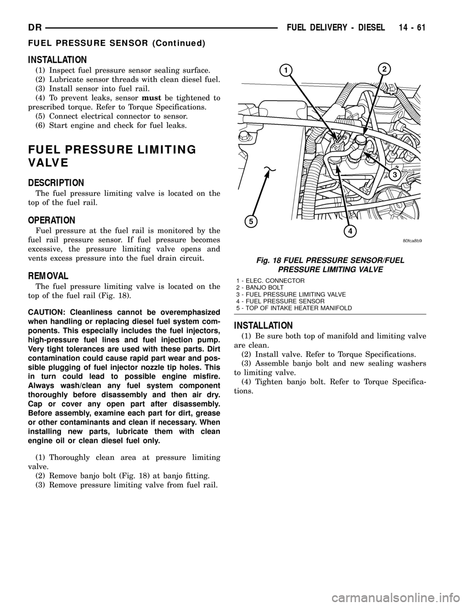
The fuel pressure limiting valve is located on the
top of the fuel rail.
OPERATION
Fuel pressure at the fuel rail is monitored by the
fuel rail pressure sensor. If fuel pressure becomes
excessive, the pressure limiting valve opens and
vents excess pressure into the fuel drain circuit.
REMOVAL
The fuel pressure limiting valve is located on the
top of the fuel rail (Fig. 18).
CAUTION: Cleanliness cannot be overemphasized
when handling or replacing diesel fuel system com-
ponents. This especially includes the fuel injectors,
high-pressure fuel lines and fuel injection pump.
Very tight tolerances are used with these parts. Dirt
contamination could cause rapid part wear and pos-
sible plugging of fuel injector nozzle tip holes. This
in turn could lead to possible engine misfire.
Always wash/clean any fuel system component
thoroughly before disassembly and then air dry.
Cap or cover any open part after disassembly.
Before assembly, examine each part for dirt, grease
or other contaminants and clean if necessary. When
installing new parts, lubricate them with clean
engine oil or clean diesel fuel only.
(1) Thoroughly clean area at pressure limiting
valve.
(2) Remove banjo bolt (Fig. 18) at banjo fitting.
(3) Remove pressure limiting valve from fuel rail.
INSTALLATION
(1) Be sure both top of manifold and limiting valve
are clean.
(2) Install valve. Refer to Torque Specifications.
(3) Assemble banjo bolt and new sealing washers
to limiting valve.
(4) Tighten banjo bolt. Refer to Torque Specifica-
tions.
Fig. 18 FUEL PRESSURE SENSOR/FUEL
PRESSURE LIMITING VALVE
1 - ELEC. CONNECTOR
2 - BANJO BOLT
3 - FUEL PRESSURE LIMITING VALVE
4 - FUEL PRESSURE SENSOR
5 - TOP OF INTAKE HEATER MANIFOLD
DRFUEL DELIVERY - DIESEL 14 - 61
FUEL PRESSURE SENSOR (Continued)
Page 1641 of 2627

is the primary engine speed indicator for the engine
after the engine is running.
REMOVAL
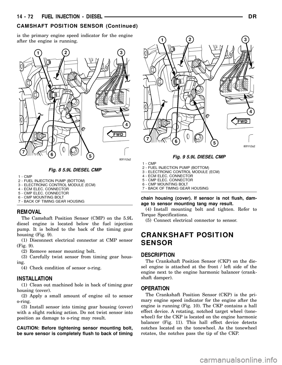
The Camshaft Position Sensor (CMP) on the 5.9L
diesel engine is located below the fuel injection
pump. It is bolted to the back of the timing gear
housing (Fig. 9).
(1) Disconnect electrical connector at CMP sensor
(Fig. 9).
(2) Remove sensor mounting bolt.
(3) Carefully twist sensor from timing gear hous-
ing.
(4) Check condition of sensor o-ring.
INSTALLATION
(1) Clean out machined hole in back of timing gear
housing (cover).
(2) Apply a small amount of engine oil to sensor
o-ring.
(3) Install sensor into timing gear housing (cover)
with a slight rocking action. Do not twist sensor into
position as damage to o-ring may result.
CAUTION: Before tightening sensor mounting bolt,
be sure sensor is completely flush to back of timingchain housing (cover). If sensor is not flush, dam-
age to sensor mounting tang may result.
(4) Install mounting bolt and tighten. Refer to
Torque Specifications.
(5) Connect electrical connector to sensor.
CRANKSHAFT POSITION
SENSOR
DESCRIPTION
The Crankshaft Position Sensor (CKP) on the die-
sel engine is attached at the front / left side of the
engine next to the engine harmonic balancer (crank-
shaft damper).
OPERATION
The Crankshaft Position Sensor (CKP) is the pri-
mary engine speed indicator for the engine after the
engine is running (Fig. 10). The CKP contains a hall
effect device. A rotating, notched target wheel (tone-
wheel) for the CKP is located on the engine harmonic
balancer (Fig. 11). This hall effect device detects
notches located on the tonewheel. As the tonewheel
rotates, the notches pass the tip of the CKP.
Fig. 8 5.9L DIESEL CMP
1 - CMP
2 - FUEL INJECTION PUMP (BOTTOM)
3 - ELECTRONIC CONTROL MODULE (ECM)
4 - ECM ELEC. CONNECTOR
5 - CMP ELEC. CONNECTOR
6 - CMP MOUNTING BOLT
7 - BACK OF TIMING GEAR HOUSING
Fig. 9 5.9L DIESEL CMP
1 - CMP
2 - FUEL INJECTION PUMP (BOTTOM)
3 - ELECTRONIC CONTROL MODULE (ECM)
4 - ECM ELEC. CONNECTOR
5 - CMP ELEC. CONNECTOR
6 - CMP MOUNTING BOLT
7 - BACK OF TIMING GEAR HOUSING
14 - 72 FUEL INJECTION - DIESELDR
CAMSHAFT POSITION SENSOR (Continued)
Page 1646 of 2627

INSTALLATION
(1)Inspect fuel injector:
(a) Look for burrs on injector inlet.
(b) Check nozzle holes for hole erosion or plug-
ging.
(c) Inspect end of nozzle for burrs or rough
machine marks.
(d) Look for cracks at nozzle end.
(e) If any of these conditions occur, replace injec-
tor.
(2) Thoroughly clean fuel injector cylinder head
bore. Blow out bore hole with compressed air.
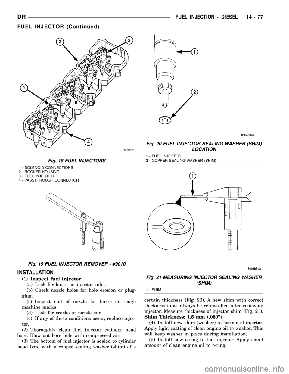
(3) The bottom of fuel injector is sealed to cylinder
head bore with a copper sealing washer (shim) of acertain thickness (Fig. 20). A new shim with correct
thickness must always be re-installed after removing
injector. Measure thickness of injector shim (Fig. 21).
Shim Thickness: 1.5 mm (.060º)
(4) Install new shim (washer) to bottom of injector.
Apply light coating of clean engine oil to washer. This
will keep washer in place during installation.
(5) Install new o-ring to fuel injector. Apply small
amount of clean engine oil to o-ring.
Fig. 18 FUEL INJECTORS
1 - SOLENOID CONNECTIONS
2 - ROCKER HOUSING
3 - FUEL INJECTOR
4 - PASSTHROUGH CONNECTOR
Fig. 19 FUEL INJECTOR REMOVER - #9010
Fig. 20 FUEL INJECTOR SEALING WASHER (SHIM)
LOCATION
1 - FUEL INJECTOR
2 - COPPER SEALING WASHER (SHIM)
Fig. 21 MEASURING INJECTOR SEALING WASHER
(SHIM)
1 - SHIM
DRFUEL INJECTION - DIESEL 14 - 77
FUEL INJECTOR (Continued)
Page 1647 of 2627

(6) Install injector into cylinder head with male
connector port facing the intake manifold. Push down
on fuel injector mounting flange to engage o-ring and
seat injector.
(7) Tightening Sequence:
(a) Install fuel injector holdown clamp (mount-
ing flange) bolts.Do a preliminary tightening
of these bolts to 5 N´m (44 in. lbs.) torque.
This preliminary tightening insures the fuel
injector is seated and centered.
(b) After tightening, relieve bolt torque, but
leave both bolts threaded in place.
(c) Install high-pressure connector and retaining
nut. Do a preliminary tightening to 15 N´m (11 ft.
lbs.) torque.
(d) Alternately tighten injector holdown bolts to
10 N´m (89 in. lbs.) torque.
(e) Do a final tightening of the high-pressure
connector and retaining nut. Tighten to 50 N´m (37
ft. lbs.) torque.
(8) Connect injector solenoid wires and nuts to top
of injectors (Fig. 18). Tighten connector nuts to 1.25
N´m (11 in. lbs.) torque.Be very careful not to
overtighten these nuts as damage to fuel injec-
tor will occur.
(9) Install exhaust rocker arm assembly. Refer to
Engine.
(10) Set exhaust valve lash. Refer to Engine.
(11) Install high pressure fuel line. Refer to Torque
Specifications.Be sure to use a secondary
back-up wrench on the connector nut (fitting)
while torquing fuel line fitting.Refer to Fuel Line
Installation for additional information.
(12) Install valve cover. Refer to Engine.
(13) Install breather assembly.
(14) Connect negative battery cables to both bat-
teries.
FUEL INJECTOR RAIL
DESCRIPTION
The fuel injector rail is bolted to the top of the
intake manifold.
OPERATION
The fuel rail is used as a distribution device to
supply high-pressure fuel to the high-pressure fuel
lines.
REMOVAL
CAUTION: Cleanliness cannot be overemphasized
when handling or replacing diesel fuel system com-
ponents. This especially includes the fuel injectors,
high-pressure fuel lines and fuel injection pump.Very tight tolerances are used with these parts. Dirt
contamination could cause rapid part wear and pos-
sible plugging of fuel injector nozzle tip holes. This
in turn could lead to possible engine misfire.
Always wash/clean any fuel system component
thoroughly before disassembly and then air dry.
Cap or cover any open part after disassembly.
Before assembly, examine each part for dirt, grease
or other contaminants and clean if necessary. When
installing new parts, lubricate them with clean
engine oil or clean diesel fuel only.
(1) Disconnect both negative battery cables at both
batteries. Isolate ends of both cables.
(2) Disconnect electrical connector at fuel pressure
sensor.
(3) Remove banjo bolt at fuel limiting valve.
(4) Disconnect necessary wiring harness retention
clips from intake manifold.
(5) Lift 2 rubber covers to gain access to positive
(+), intake heater cable nuts. Remove 2 nuts and
remove 2 cables from studs.
(6) Carefully remove 4 high-pressure fuel lines
from top of injector rail engine. Note position of each
line while removing.Do not bend lines while
removing.
CAUTION: WHEN LOOSENING OR TIGHTENING
HIGH-PRESSURE LINES ATTACHED TO A SEPA-
RATE FITTING, USE A BACK-UP WRENCH ON FIT-
TING. DO NOT ALLOW FITTING TO ROTATE.
DAMAGE TO BOTH FUEL LINE AND FITTING WILL
RESULT.
(7) Carefully remove 2 high-pressure fuel lines at
each end of injector rail. Note position of each line
while removing.Do not bend lines while remov-
ing.
(8) Remove fuel line connecting injector pump to
fuel rail.
(9) Remove 3 injector rail mounting bolts (Fig. 22).
(10) Remove rail from top of intake manifold.
INSTALLATION
(1) Clean any dirt/debris from top of intake mani-
fold and bottom of fuel rail.
(2) Position fuel rail to top of manifold and install
3 mounting bolts. Refer to Torque Specifications.
(3) Install all high-pressure lines to rail. Refer to
Fuel Lines for procedures.
(4) Reposition wiring harness to intake manifold
and install new tie wraps.
(5) Install and tighten fuel limiting valve banjo
bolt. Refer to Torque Specifications.
(6) Connect electrical connector to fuel pressure
sensor.
(7) Position 2 positive (+) cables to intake heater
studs. Install 2 nuts.
14 - 78 FUEL INJECTION - DIESELDR
FUEL INJECTOR (Continued)
Page 1649 of 2627

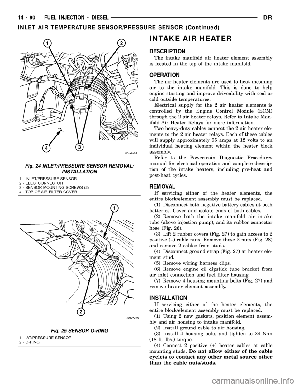
INTAKE AIR HEATER
DESCRIPTION
The intake manifold air heater element assembly
is located in the top of the intake manifold.
OPERATION
The air heater elements are used to heat incoming
air to the intake manifold. This is done to help
engine starting and improve driveability with cool or
cold outside temperatures.
Electrical supply for the 2 air heater elements is
controlled by the Engine Control Module (ECM)
through the 2 air heater relays. Refer to Intake Man-
ifold Air Heater Relays for more information.
Two heavy-duty cables connect the 2 air heater ele-
ments to the 2 air heater relays. Each of these cables
will supply approximately 95 amps at 12 volts to an
individual heating element within the heater block
assembly.
Refer to the Powertrain Diagnostic Procedures
manual for electrical operation and complete descrip-
tion of the intake heaters, including pre-heat and
post-heat cycles.
REMOVAL
If servicing either of the heater elements, the
entire block/element assembly must be replaced.
(1) Disconnect both negative battery cables at both
batteries. Cover and isolate ends of both cables.
(2) Remove both the intake manifold air intake
tube (above injection pump), and its rubber connector
hose (Fig. 26).
(3) Lift 2 rubber covers (Fig. 27) to gain access to 2
positive (+) cable nuts. Remove these 2 nuts (Fig. 28)
and remove 2 cables from studs.
(4) Disconnect ground strap (Fig. 27) at heater ele-
ment stud.
(5) Remove wiring harness clips.
(6) Remove engine oil dipstick tube bracket from
air inlet connection and fuel filter housing.
(7) Remove 4 housing mounting bolts (Fig. 27) and
remove heater element assembly.
INSTALLATION
If servicing either of the heater elements, the
entire block/element assembly must be replaced.
(1) Using 2 new gaskets, position element assem-
bly and air housing to intake manifold.
(2) Install ground cable to air housing.
(3) Install 4 housing bolts and tighten to 24 N´m
(18 ft. lbs.) torque.
(4) Connect 2 positive (+) heater cables at cable
mounting studs.Do not allow either of the cable
eyelets to contact any other metal source other
than the cable nuts/studs.
Fig. 24 INLET/PRESSURE SENSOR REMOVAL/
INSTALLATION
1 - INLET/PRESSURE SENSOR
2 - ELEC. CONNECTOR
3 - SENSOR MOUNTING SCREWS (2)
4 - TOP OF AIR FILTER COVER
Fig. 25 SENSOR O-RING
1 - IAT/PRESSURE SENSOR
2 - O-RING
14 - 80 FUEL INJECTION - DIESELDR
INLET AIR TEMPERATURE SENSOR/PRESSURE SENSOR (Continued)
Page 1650 of 2627

(5) Install engine oil dipstick tube and mounting
bolt.
(6) Connect rubber connector hose and intake tube
to air intake housing. Tighten clamp bolts to 11 N´m
(95 in. lbs.) torque.
(7) Connect both negative battery cables at both
batteries.
Fig. 26 INTAKE TUBE AND CONNECTING HOSE
1 - MANIFOLD ABOVE HEATERS
2 - RUBBER CONNECTING HOSE
3 - METAL INTAKE TUBE
4 - CLAMPS (2)
Fig. 27 AIR HEATER MANIFOLD
1 - GROUND CABLE
2 - MOUNTING BOLTS (4)
3 - RUBBER COVERS
4 - OIL DIPSTICK TUBE
5 - DIPSTICK MOUNTING BOLT
6 - NUT (GROUND CABLE)
Fig. 28 AIR HEATER ELEMENTS
1 - MOUNTING BOLTS (4)
2 - AIR HEATER MANIFOLD
3 - INTAKE MANIFOLD
4 - HEATER ELEMENTS
5 - LOWER GASKET
6 - NUTS (2) POSITIVE CABLES
7 - UPER GASKET
DRFUEL INJECTION - DIESEL 14 - 81
INTAKE AIR HEATER (Continued)
Page 1651 of 2627

INTAKE AIR HEATER RELAY
DESCRIPTION
The 2 intake manifold air heater relays are located
in the engine compartment. They are attached to a
common bracket. This bracket is attached to the
right battery tray (Fig. 29).
OPERATION
The Engine Control Module (ECM) operates the 2
heating elements through the 2 intake manifold air
heater relays.
Refer to Powertrain Diagnostic Procedures for an
electrical operation and complete description of the
intake heaters, including pre-heat and post-heat
cycles.
REMOVAL
The 2 intake manifold air heater relays are located
in the engine compartment. They are attached to a
common bracket. This bracket is attached to the
right battery tray (Fig. 29).
The mounting bracket and both relays are replaced
as an assembly.
(1) Disconnect both negative battery cables at both
batteries.
(2) Disconnect four relay trigger wires at both
relays. Note position of wiring before removing.
(3) Lift four rubber shields from all 4 cables.(4) Remove four nuts at cable connectors. Note
position of wiring before removing.
(5) Remove relay mounting bracket bolts and
remove relay assembly.
INSTALLATION
(1) Install relay assembly to battery tray. Tighten
mounting bolts to 4.5 N´m (40 in. lbs.) torque.
(2) Connect eight electrical connectors to relays.
(3) Connect battery cables to both batteries.
INTAKE AIR TEMPERATURE
SENSOR/MAP SENSOR
DESCRIPTION
The combination, dual function Intake Manifold
Air Temperature Sensor/MAP Sensor is installed into
the top of the intake manifold.
OPERATION
The combination, dual function Intake Manifold
Air Temperature Sensor/MAP Sensor is installed into
the top of the intake manifold with the sensor ele-
ment extending into the air stream.
The IAT portion of the sensor provides an input
voltage to the Engine Control Module (ECM) indicat-
ing intake manifold air temperature. The MAP por-
tion of the sensor provides an input voltage to the
ECM indicating turbocharger boost pressure.
REMOVAL
The combination, dual function Intake Manifold
Air Temperature Sensor/MAP (IAT/MAP) sensor is
installed into the top of the intake manifold (Fig. 30).
(1) Clean area around sensor.
(2) Disconnect electrical connector from IAT/MAP
sensor.
(3) Remove two T-15 Torx headed screws.
(4) Remove sensor from intake manifold.
(5) Check condition of sensor o-ring (Fig. 31).
INSTALLATION
(1) Check condition of sensor o-ring.
(2) Lubricate sensor o-ring with clean engine oil.
(3) Clean sensor mounting area at intake mani-
fold.
(4) Position sensor into intake manifold.
(5) Install and tighten 2 sensor mounting screws
to 1 N´m (9 in. lbs.) torque.
(6) Connect electrical connector to sensor.
Fig. 29 INTAKE MANIFOLD AIR HEATER RELAYS
1 - BATTERY
2 - CABLES TO INTAKE HEATERS
3 - RELAY TRIGGER WIRES
4 - INTAKE AIR HEATER RELAYS (2)
14 - 82 FUEL INJECTION - DIESELDR