1998 DODGE RAM 1500 service
[x] Cancel search: servicePage 2226 of 2627
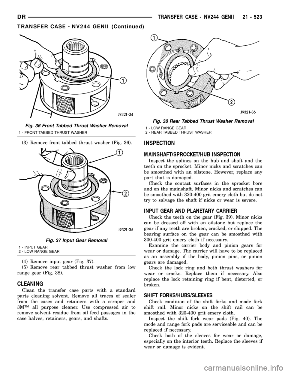
(3) Remove front tabbed thrust washer (Fig. 36).
(4) Remove input gear (Fig. 37).
(5) Remove rear tabbed thrust washer from low
range gear (Fig. 38).
CLEANING
Clean the transfer case parts with a standard
parts cleaning solvent. Remove all traces of sealer
from the cases and retainers with a scraper and
3MŸ all purpose cleaner. Use compressed air to
remove solvent residue from oil feed passages in the
case halves, retainers, gears, and shafts.
INSPECTION
MAINSHAFT/SPROCKET/HUB INSPECTION
Inspect the splines on the hub and shaft and the
teeth on the sprocket. Minor nicks and scratches can
be smoothed with an oilstone. However, replace any
part that is damaged.
Check the contact surfaces in the sprocket bore
and on the mainshaft. Minor nicks and scratches can
be smoothed with 320-400 grit emery cloth but do not
try to salvage the shaft if nicks or wear is severe.
INPUT GEAR AND PLANETARY CARRIER
Check the teeth on the gear (Fig. 39). Minor nicks
can be dressed off with an oilstone but replace the
gear if any teeth are broken, cracked, or chipped. The
bearing surface on the gear can be smoothed with
300-400 grit emery cloth if necessary.
Examine the carrier body and pinion gears for
wear or damage. The carrier will have to be replaced
as an assembly if the body, pinion pins, or pinion
gears are damaged.
Check the lock ring and both thrust washers for
wear or cracks. Replace them if necessary. Also
replace the lock retaining ring if bent, distorted, or
broken.
SHIFT FORKS/HUBS/SLEEVES
Check condition of the shift forks and mode fork
shift rail. Minor nicks on the shift rail can be
smoothed with 320-400 grit emery cloth.
Inspect the shift fork wear pads (Fig. 40). The
mode and range fork pads are serviceable and can be
replaced if necessary.
Check both of the sleeves for wear or damage,
especially on the interior teeth. Replace the sleeves if
wear or damage is evident.
Fig. 36 Front Tabbed Thrust Washer Removal
1 - FRONT TABBED THRUST WASHER
Fig. 37 Input Gear Removal
1 - INPUT GEAR
2 - LOW RANGE GEAR
Fig. 38 Rear Tabbed Thrust Washer Removal
1 - LOW RANGE GEAR
2 - REAR TABBED THRUST WASHER
DRTRANSFER CASE - NV244 GENII 21 - 523
TRANSFER CASE - NV244 GENII (Continued)
Page 2227 of 2627

REAR EXTENSION HOUSING
Inspect the extension housing seal and bushing.
Replace both components if either show any sign of
wear or damage.
FRONT OUTPUT SHAFT AND DRIVE CHAIN
Inspect the shaft splines and bearing surfaces.
Minor nicks on the splines can be smoothed with an
oilstone. Use 320-400 grit emery to smooth minor
scratches on the shaft bearing surfaces. Replace the
shaft if the bearing surfaces are scored or if any of
the splines are cracked or broken.Examine the drive chain and shaft bearings.
Replace the chain and both sprockets if the chain is
stretched, distorted, or if any of the links bind.
Replace the bearings if rough, or noisy.
LOW RANGE ANNULUS GEAR
Inspect annulus gear condition carefully. The gear
is only serviced as part of the front case. If the gear
is damaged, it will be necessary to replace the gear
and front case as an assembly. Do not attempt to
remove the gear (Fig. 41)
Fig. 39 Input Gear and Carrier Components
1 - PLANETARY CARRIER 4 - CARRIER LOCK RING
2 - REAR THRUST WASHER 5 - CARRIER LOCK RETAINING RING
3 - FRONT THRUST WASHER 6 - INPUT GEAR
Fig. 40 Shift Fork and Wear Pad Locations
1 - RANGE FORK
2 - MODE FORK
3 - WEAR PADS (SERVICEABLE)
4 - WEAR PADS (SERVICEABLE)
Fig. 41 Low Range Annulus Gear
1 - FRONT CASE
2 - LOW RANGE ANNULUS GEAR
21 - 524 TRANSFER CASE - NV244 GENIIDR
TRANSFER CASE - NV244 GENII (Continued)
Page 2228 of 2627
FRONT AND REAR CASES
Inspect the cases for wear and damage.
Check case condition. If leaks were a problem, look
for gouges and severe scoring of case sealing sur-
faces. Also make sure the front case mounting studs
are in good condition.
Check the front case mounting studs and vent
tube. The tube can be secured with LoctiteŸ 271 or
680 if loose. The stud threads can be cleaned up with
a die if necessary. Also check condition of the fill/
drain plug threads in the rear case. The threads can
be repaired with a thread chaser or tap if necessary.
Or the threads can be repaired with Helicoiltstain-
less steel inserts if required.
OIL PUMP/OIL PICKUP
Examine the oil pump pickup parts. Replace the
pump if any part appears to be worn or damaged. Do
not disassemble the pump as individual parts are not
available. The pump is only available as a complete
assembly. The pickup screen, hose, and tube are the
only serviceable parts and are available separately.
ASSEMBLY
BEARINGS AND SEALS
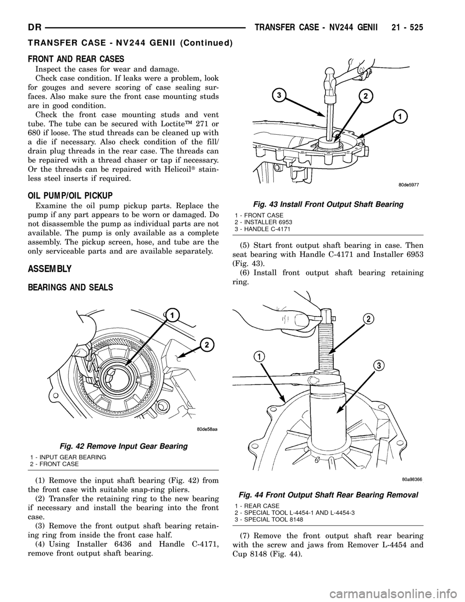
(1) Remove the input shaft bearing (Fig. 42) from
the front case with suitable snap-ring pliers.
(2) Transfer the retaining ring to the new bearing
if necessary and install the bearing into the front
case.
(3) Remove the front output shaft bearing retain-
ing ring from inside the front case half.
(4) Using Installer 6436 and Handle C-4171,
remove front output shaft bearing.(5) Start front output shaft bearing in case. Then
seat bearing with Handle C-4171 and Installer 6953
(Fig. 43).
(6) Install front output shaft bearing retaining
ring.
(7) Remove the front output shaft rear bearing
with the screw and jaws from Remover L-4454 and
Cup 8148 (Fig. 44).
Fig. 42 Remove Input Gear Bearing
1 - INPUT GEAR BEARING
2 - FRONT CASE
Fig. 43 Install Front Output Shaft Bearing
1 - FRONT CASE
2 - INSTALLER 6953
3 - HANDLE C-4171
Fig. 44 Front Output Shaft Rear Bearing Removal
1 - REAR CASE
2 - SPECIAL TOOL L-4454-1 AND L-4454-3
3 - SPECIAL TOOL 8148
DRTRANSFER CASE - NV244 GENII 21 - 525
TRANSFER CASE - NV244 GENII (Continued)
Page 2258 of 2627
SHIFT FORKS/HUBS/SLEEVES
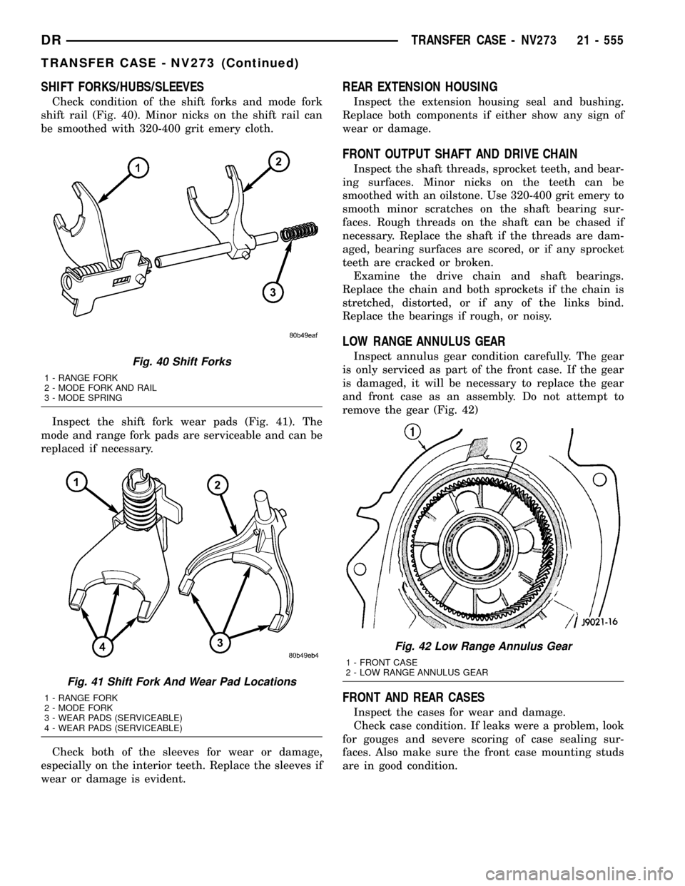
Check condition of the shift forks and mode fork
shift rail (Fig. 40). Minor nicks on the shift rail can
be smoothed with 320-400 grit emery cloth.
Inspect the shift fork wear pads (Fig. 41). The
mode and range fork pads are serviceable and can be
replaced if necessary.
Check both of the sleeves for wear or damage,
especially on the interior teeth. Replace the sleeves if
wear or damage is evident.
REAR EXTENSION HOUSING
Inspect the extension housing seal and bushing.
Replace both components if either show any sign of
wear or damage.
FRONT OUTPUT SHAFT AND DRIVE CHAIN
Inspect the shaft threads, sprocket teeth, and bear-
ing surfaces. Minor nicks on the teeth can be
smoothed with an oilstone. Use 320-400 grit emery to
smooth minor scratches on the shaft bearing sur-
faces. Rough threads on the shaft can be chased if
necessary. Replace the shaft if the threads are dam-
aged, bearing surfaces are scored, or if any sprocket
teeth are cracked or broken.
Examine the drive chain and shaft bearings.
Replace the chain and both sprockets if the chain is
stretched, distorted, or if any of the links bind.
Replace the bearings if rough, or noisy.
LOW RANGE ANNULUS GEAR
Inspect annulus gear condition carefully. The gear
is only serviced as part of the front case. If the gear
is damaged, it will be necessary to replace the gear
and front case as an assembly. Do not attempt to
remove the gear (Fig. 42)
FRONT AND REAR CASES
Inspect the cases for wear and damage.
Check case condition. If leaks were a problem, look
for gouges and severe scoring of case sealing sur-
faces. Also make sure the front case mounting studs
are in good condition.
Fig. 40 Shift Forks
1 - RANGE FORK
2 - MODE FORK AND RAIL
3 - MODE SPRING
Fig. 41 Shift Fork And Wear Pad Locations
1 - RANGE FORK
2 - MODE FORK
3 - WEAR PADS (SERVICEABLE)
4 - WEAR PADS (SERVICEABLE)
Fig. 42 Low Range Annulus Gear
1 - FRONT CASE
2 - LOW RANGE ANNULUS GEAR
DRTRANSFER CASE - NV273 21 - 555
TRANSFER CASE - NV273 (Continued)
Page 2259 of 2627
Check the front case mounting studs and vent
tube. The tube can be secured with LoctiteŸ 271 or
680 if loose. The stud threads can be cleaned up with
a die if necessary. Also check condition of the fill/
drain plug threads in the rear case. The threads can
be repaired with a thread chaser or tap if necessary.
Or the threads can be repaired with Helicoiltstain-
less steel inserts if required.
OIL PUMP/OIL PICKUP
Examine the oil pump pickup parts. Replace the
pump if any part appears to be worn or damaged. Do
not disassemble the pump as individual parts are not
available. The pump is only available as a complete
assembly. The pickup screen, hose, and tube are the
only serviceable parts and are available separately.
ASSEMBLY
BEARINGS AND SEALS
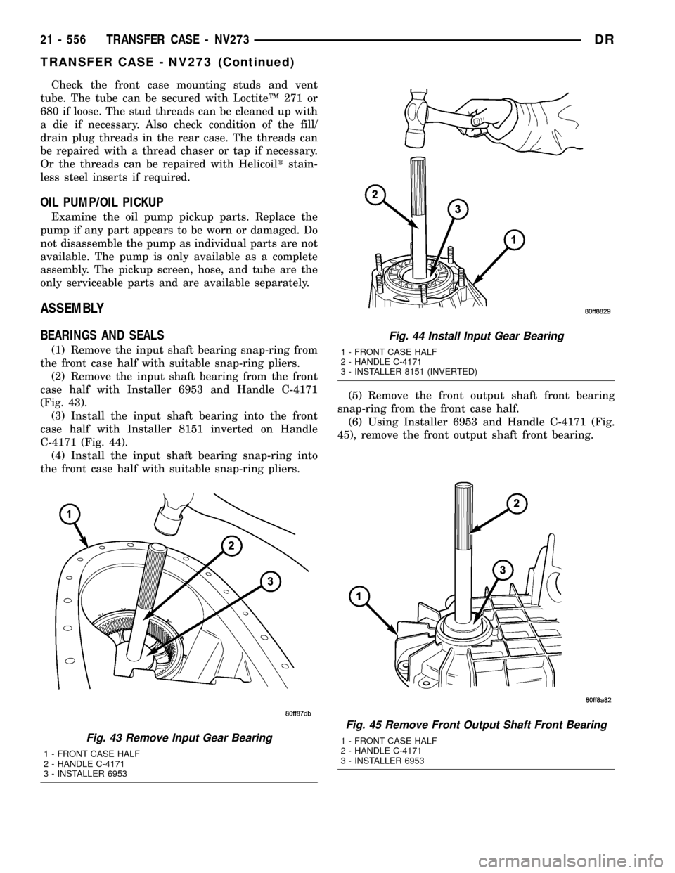
(1) Remove the input shaft bearing snap-ring from
the front case half with suitable snap-ring pliers.
(2) Remove the input shaft bearing from the front
case half with Installer 6953 and Handle C-4171
(Fig. 43).
(3) Install the input shaft bearing into the front
case half with Installer 8151 inverted on Handle
C-4171 (Fig. 44).
(4) Install the input shaft bearing snap-ring into
the front case half with suitable snap-ring pliers.(5) Remove the front output shaft front bearing
snap-ring from the front case half.
(6) Using Installer 6953 and Handle C-4171 (Fig.
45), remove the front output shaft front bearing.
Fig. 45 Remove Front Output Shaft Front Bearing
1 - FRONT CASE HALF
2 - HANDLE C-4171
3 - INSTALLER 6953Fig. 43 Remove Input Gear Bearing
1 - FRONT CASE HALF
2 - HANDLE C-4171
3 - INSTALLER 6953
Fig. 44 Install Input Gear Bearing
1 - FRONT CASE HALF
2 - HANDLE C-4171
3 - INSTALLER 8151 (INVERTED)
21 - 556 TRANSFER CASE - NV273DR
TRANSFER CASE - NV273 (Continued)
Page 2281 of 2627
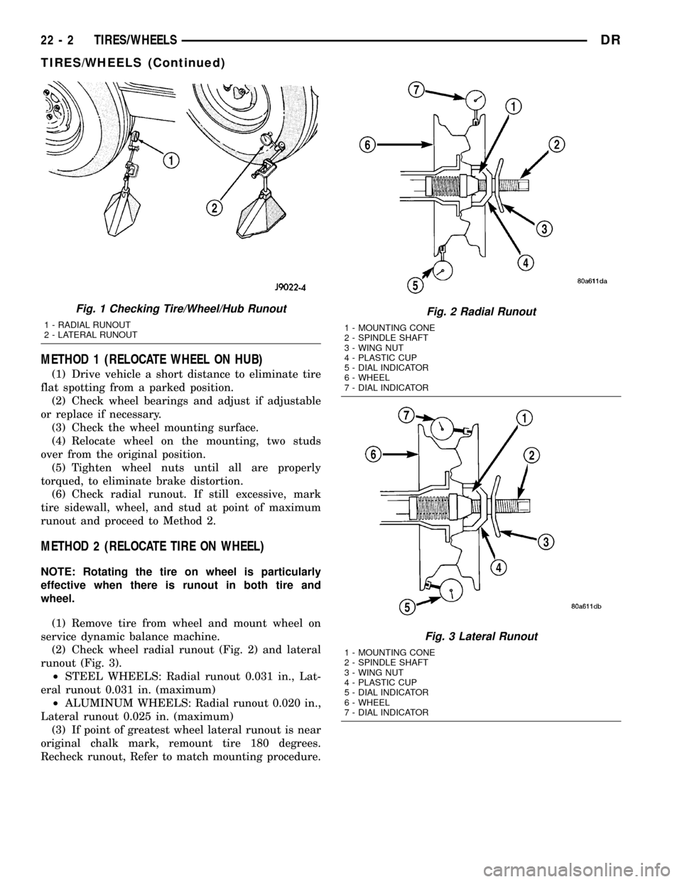
METHOD 1 (RELOCATE WHEEL ON HUB)
(1) Drive vehicle a short distance to eliminate tire
flat spotting from a parked position.
(2) Check wheel bearings and adjust if adjustable
or replace if necessary.
(3) Check the wheel mounting surface.
(4) Relocate wheel on the mounting, two studs
over from the original position.
(5) Tighten wheel nuts until all are properly
torqued, to eliminate brake distortion.
(6) Check radial runout. If still excessive, mark
tire sidewall, wheel, and stud at point of maximum
runout and proceed to Method 2.
METHOD 2 (RELOCATE TIRE ON WHEEL)
NOTE: Rotating the tire on wheel is particularly
effective when there is runout in both tire and
wheel.
(1) Remove tire from wheel and mount wheel on
service dynamic balance machine.
(2) Check wheel radial runout (Fig. 2) and lateral
runout (Fig. 3).
²STEEL WHEELS: Radial runout 0.031 in., Lat-
eral runout 0.031 in. (maximum)
²ALUMINUM WHEELS: Radial runout 0.020 in.,
Lateral runout 0.025 in. (maximum)
(3) If point of greatest wheel lateral runout is near
original chalk mark, remount tire 180 degrees.
Recheck runout, Refer to match mounting procedure.
Fig. 1 Checking Tire/Wheel/Hub Runout
1 - RADIAL RUNOUT
2 - LATERAL RUNOUT
Fig. 2 Radial Runout
1 - MOUNTING CONE
2 - SPINDLE SHAFT
3 - WING NUT
4 - PLASTIC CUP
5 - DIAL INDICATOR
6 - WHEEL
7 - DIAL INDICATOR
Fig. 3 Lateral Runout
1 - MOUNTING CONE
2 - SPINDLE SHAFT
3 - WING NUT
4 - PLASTIC CUP
5 - DIAL INDICATOR
6 - WHEEL
7 - DIAL INDICATOR
22 - 2 TIRES/WHEELSDR
TIRES/WHEELS (Continued)
Page 2282 of 2627

STANDARD PROCEDURE
STANDARD PROCEDURE - TIRE ROTATION
Tires on the front and rear axles operate at differ-
ent loads and perform different steering, driving, and
braking functions. For these reasons, the tires wear
at unequal rates. They may also develop irregular
wear patterns. These effects can be reduced by rotat-
ing the tires according to the maintenance schedule
in the Owners Manual. This will improve tread life,
traction and maintain a smooth quiet ride.
The recommended method of tire rotation is (Fig.
4) & (Fig. 5). Other methods can be used, but may
not provide the same tire longevity benefits.
CAUTION: 3500 Dual rear tires have a new tire rota-
tion pattern. This is to accommodate the asymmet-
rical design of the ON/OFF road tires and the use of
the outlined white letter (OWL) tires. When replac-
ing a flat, the spare tire may have to be remounted
on the rim or installed at a different location to
maintain the correct placement of the asymmetrical
design or the (OWL).
STANDARD PROCEDURE - MATCH MOUNTING
Wheels and tires are match mounted at the factory.
This means that the high spot of the tire is matched
to the low spot on the wheel rim. Each are marked
with a bright colored temporary label on the out-
board surface for alignment. The wheel is also
marked permanently on the inside of the rim in the
tire well. This permanent mark may be a paint dot
or line, a permanent label or a stamped impression
such as an X. An optional location mark is a small
spherical indentation on the vertical face of the out-
board flange on some non styled base steel wheels.
The tire must be removed to locate the permanent
mark on the inside of the wheel.
Before dismounting a tire from its wheel, a refer-
ence mark should be placed on the tire at the valve
stem location. This reference will ensure that it is
remounted in the original position on the wheel.
(1) Remove the tire and wheel assembly from the
vehicle and mount on a service dynamic balance
machine.
(2) Measure the total runout on the center of the
tire tread rib with a dial indicator. Record the indi-
cator reading. Mark the tire to indicate the high spot.
Place a mark on the tire at the valve stem location
(Fig. 6).
Fig. 4 TIRE ROTATION PATTERN - SINGLE REAR
WHEEL (SRW)
Fig. 5 TIRE ROTATION PATTERN - DUAL REAR
WHEELS (DRW)
Fig. 6 First Measurement On Tire
1 - REFERENCE MARK
2 - 1ST MEASUREMENT HIGH SPOT MARK TIRE AND RIM
3 - WHEEL
4 - VALVE STEM
DRTIRES/WHEELS 22 - 3
TIRES/WHEELS (Continued)
Page 2283 of 2627

(3) Break down the tire and remount it 180
degrees on the rim (Fig. 7).
(4) Measure the total indicator runout again. Mark
the tire to indicate the high spot.
(5) If runout is still excessive, the following proce-
dures must be done.
²If the high spot is within 101.6 mm (4.0 in.) of
the first spot and is still excessive, replace the tire.
²If the high spot is within 101.6 mm (4.0 in.) of
the first spot on the wheel, the wheel may be out of
specifications. Refer to Wheel and Tire Runout.
²If the high spot is NOT within 101.6 mm (4.0
in.) of either high spot, draw an arrow on the tread
from second high spot to first. Break down the tire
and remount it 90 degrees on rim in that direction
(Fig. 8). This procedure will normally reduce the
runout to an acceptable amount, if not replace the
rim.
STANDARD PROCEDURE - TIRE AND WHEEL
BALANCE
It is recommended that a two plane service
dynamic balancer be used when a tire and wheel
assembly require balancing. Refer to balancer opera-
tion instructions for proper cone mounting proce-
dures. Typically use front cone mounting method for
steel wheels. For aluminum wheel use back cone
mounting method without cone spring.NOTE: Static should be used only when a two plane
balancer is not available.
NOTE: Cast aluminum and forged aluminum wheels
require coated balance weights and special align-
ment equipment.
Wheel balancing can be accomplished with either
on or off vehicle equipment. When using on-vehicle
balancing equipment, remove the opposite wheel/tire.
Off-vehicle balancing is recommended.
For static balancing, find the location of the heavy
spot causing the imbalance. Counter balance wheel
directly opposite the heavy spot. Determine weight
required to counter balance the area of imbalance.
Place half of this weight on theinnerrim flange and
the other half on theouterrim flange (Fig. 9).
For dynamic balancing, the balancing equipment is
designed to locate the amount of weight to be applied
to both the inner and outer rim flange (Fig. 10).
Fig. 7 Remount Tire 180 Degrees
1 - VALVE STEM
2 - REFERENCE MARK
Fig. 8 Remount Tire 90 Degrees In Direction of
Arrow
1 - 2ND HIGH SPOT ON TIRE
2 - 1ST HIGH SPOT ON TIRE
22 - 4 TIRES/WHEELSDR
TIRES/WHEELS (Continued)