1998 DODGE RAM 1500 transfer
[x] Cancel search: transferPage 2273 of 2627

Installer - 8891
Socket - 9033
Installer, Bearing - 9035
Installer, Seal - 9036
Installer, Seal - 9037
21 - 570 TRANSFER CASE - NV273DR
TRANSFER CASE - NV273 (Continued)
Page 2274 of 2627

EXTENSION HOUSING SEAL
AND DUST BOOT
REMOVAL
(1) Raise and support vehicle.
(2) Remove rear propeller shaft. (Refer to 3 - DIF-
FERENTIAL & DRIVELINE/PROPELLER SHAFT/
PROPELLER SHAFT - REMOVAL)
(3) Use a suitable chisel or pry tool to remove the
rear extension housing dust boot (Fig. 89).
(4) Use a suitable chisel or pry tool to remove the
rear extension housing seal.
INSTALLATION
(1) Clean fluid residue from sealing surface and
inspect for defects.
(2) Install the extension housing dust boot and
seal assembly with Installer 9037 and Handle C-4171
(Fig. 90).
(3) Install propeller shaft. (Refer to 3 - DIFFER-
ENTIAL & DRIVELINE/PROPELLER SHAFT/PRO-
PELLER SHAFT - INSTALLATION)
(4) Verify proper transfer case fluid level.
(5) Lower vehicle.
FLUID
STANDARD PROCEDURE - FLUID DRAIN AND
REFILL
The fill and drain plugs are both in the rear case
(Fig. 91).
(1) Raise vehicle.(2) Position drain pan under transfer case.
(3) Remove drain and fill plugs and drain lubri-
cant completely.
(4) Install drain plug. Tighten plug to 41-54 N´m
(30-40 ft. lbs.).
(5) Remove drain pan.
Fig. 89 Remove Extension Housing Dust Boot
1 - EXTENSION HOUSING
2 - DUST BOOT
Fig. 90 Install Extension Housing Seal
1 - EXTENSION HOUSING
2 - HANDLE C-4171
3 - INSTALLER 9037
Fig. 91 Drain and Fill Locations
1 - FILL HOLE
2 - DRAIN HOLE
DRTRANSFER CASE - NV273 21 - 571
Page 2275 of 2627

(6) Fill transfer case to bottom edge of fill plug
opening with MopartATF +4, Automatic Transmis-
sion fluid.
(7) Install and tighten fill plug to 41-54 N´m
(30-40 ft. lbs.).
(8) Lower vehicle.
FRONT OUTPUT SHAFT SEAL
REMOVAL
(1) Remove the front propeller shaft (Refer to 3 -
DIFFERENTIAL & DRIVELINE/PROPELLER
SHAFT/PROPELLER SHAFT - REMOVAL).
(2) Install two bolts 180É apart into the front out-
put shaft companion flange.
(3) Place holder over the bolts and against the
companion flange (Fig. 92).
(4) Remove and discard the front companion flange
nut.
(5) Remove the companion flange from the front
output shaft. It may be necessary to use Flange
puller 8992 to remove the companion flange.
(6) Using a screw and a slide hammer, remove the
front output shaft seal.
INSTALLATION
(1) Install the new front output shaft seal with
Installer MB991168A.
(2) Install the front companion flange onto the
front output shaft.
(3) Install two bolts 180É apart into the front out-
put shaft companion flange.
(4) Place holder over the bolts and against the
companion flange (Fig. 93).
(5) Install a new front companion flange nut.
Tighten the companion flange nut to 258-312 N´m
(190-230 ft.lbs.).
(6) Install front propeller shaft (Refer to 3 - DIF-
FERENTIAL & DRIVELINE/PROPELLER SHAFT/
PROPELLER SHAFT - INSTALLATION).
Fig. 92 Remove Companion Flange Nut
1 - HOLDER 6719
2 - BOLTS
Fig. 93 Install Companion Flange Nut
1 - HOLDER 6719
2 - BOLTS
21 - 572 TRANSFER CASE - NV273DR
FLUID (Continued)
Page 2276 of 2627

MODE SENSOR
DESCRIPTION
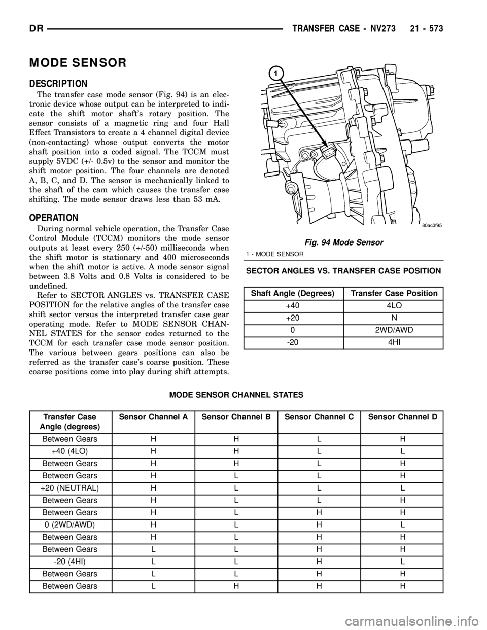
The transfer case mode sensor (Fig. 94) is an elec-
tronic device whose output can be interpreted to indi-
cate the shift motor shaft's rotary position. The
sensor consists of a magnetic ring and four Hall
Effect Transistors to create a 4 channel digital device
(non-contacting) whose output converts the motor
shaft position into a coded signal. The TCCM must
supply 5VDC (+/- 0.5v) to the sensor and monitor the
shift motor position. The four channels are denoted
A, B, C, and D. The sensor is mechanically linked to
the shaft of the cam which causes the transfer case
shifting. The mode sensor draws less than 53 mA.
OPERATION
During normal vehicle operation, the Transfer Case
Control Module (TCCM) monitors the mode sensor
outputs at least every 250 (+/-50) milliseconds when
the shift motor is stationary and 400 microseconds
when the shift motor is active. A mode sensor signal
between 3.8 Volts and 0.8 Volts is considered to be
undefined.
Refer to SECTOR ANGLES vs. TRANSFER CASE
POSITION for the relative angles of the transfer case
shift sector versus the interpreted transfer case gear
operating mode. Refer to MODE SENSOR CHAN-
NEL STATES for the sensor codes returned to the
TCCM for each transfer case mode sensor position.
The various between gears positions can also be
referred as the transfer case's coarse position. These
coarse positions come into play during shift attempts.SECTOR ANGLES VS. TRANSFER CASE POSITION
Shaft Angle (Degrees) Transfer Case Position
+40 4LO
+20 N
0 2WD/AWD
-20 4HI
MODE SENSOR CHANNEL STATES
Transfer Case
Angle (degrees)Sensor Channel A Sensor Channel B Sensor Channel C Sensor Channel D
Between Gears H H L H
+40 (4LO) H H L L
Between Gears H H L H
Between Gears H L L H
+20 (NEUTRAL) H L L L
Between Gears H L L H
Between Gears H L H H
0 (2WD/AWD) H L H L
Between Gears H L H H
Between Gears L L H H
-20 (4HI) L L H L
Between Gears L L H H
Between Gears L H H H
Fig. 94 Mode Sensor
1 - MODE SENSOR
DRTRANSFER CASE - NV273 21 - 573
Page 2277 of 2627

SELECTOR SWITCH
DESCRIPTION
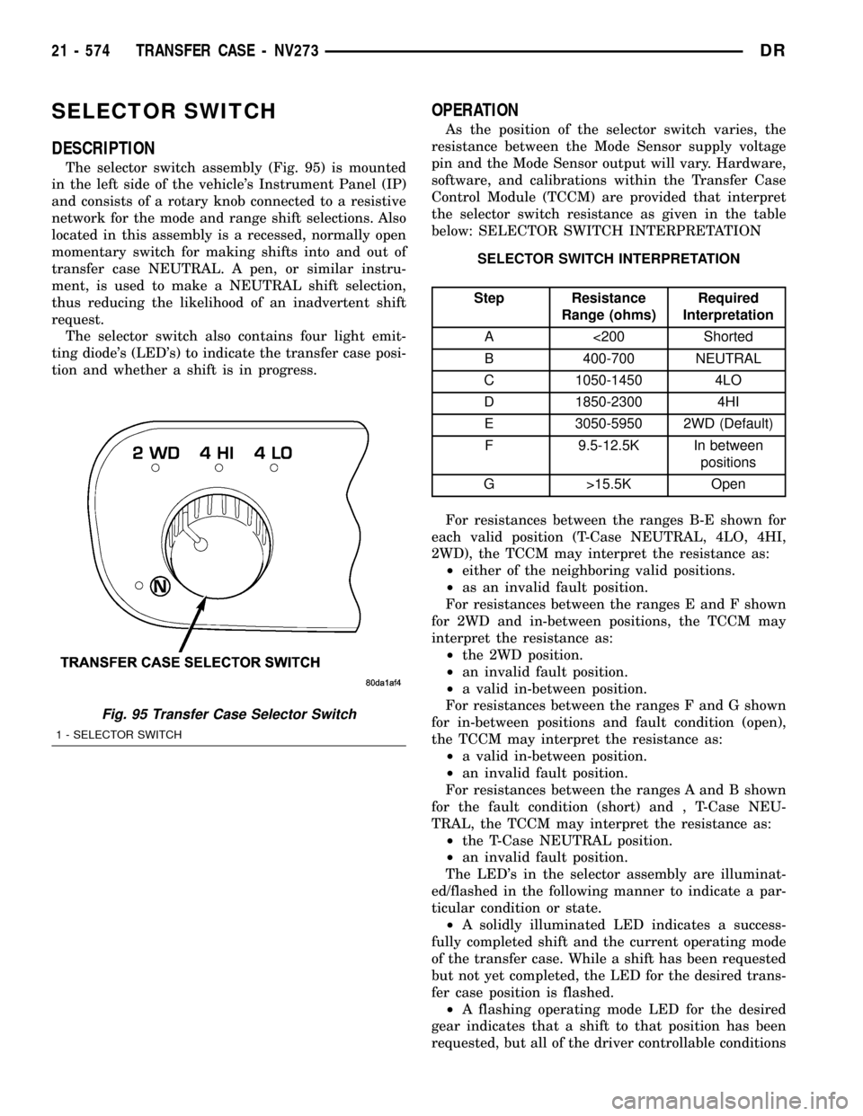
The selector switch assembly (Fig. 95) is mounted
in the left side of the vehicle's Instrument Panel (IP)
and consists of a rotary knob connected to a resistive
network for the mode and range shift selections. Also
located in this assembly is a recessed, normally open
momentary switch for making shifts into and out of
transfer case NEUTRAL. A pen, or similar instru-
ment, is used to make a NEUTRAL shift selection,
thus reducing the likelihood of an inadvertent shift
request.
The selector switch also contains four light emit-
ting diode's (LED's) to indicate the transfer case posi-
tion and whether a shift is in progress.
OPERATION
As the position of the selector switch varies, the
resistance between the Mode Sensor supply voltage
pin and the Mode Sensor output will vary. Hardware,
software, and calibrations within the Transfer Case
Control Module (TCCM) are provided that interpret
the selector switch resistance as given in the table
below: SELECTOR SWITCH INTERPRETATION
SELECTOR SWITCH INTERPRETATION
Step Resistance
Range (ohms)Required
Interpretation
A <200 Shorted
B 400-700 NEUTRAL
C 1050-1450 4LO
D 1850-2300 4HI
E 3050-5950 2WD (Default)
F 9.5-12.5K In between
positions
G >15.5K Open
For resistances between the ranges B-E shown for
each valid position (T-Case NEUTRAL, 4LO, 4HI,
2WD), the TCCM may interpret the resistance as:
²either of the neighboring valid positions.
²as an invalid fault position.
For resistances between the ranges E and F shown
for 2WD and in-between positions, the TCCM may
interpret the resistance as:
²the 2WD position.
²an invalid fault position.
²a valid in-between position.
For resistances between the ranges F and G shown
for in-between positions and fault condition (open),
the TCCM may interpret the resistance as:
²a valid in-between position.
²an invalid fault position.
For resistances between the ranges A and B shown
for the fault condition (short) and , T-Case NEU-
TRAL, the TCCM may interpret the resistance as:
²the T-Case NEUTRAL position.
²an invalid fault position.
The LED's in the selector assembly are illuminat-
ed/flashed in the following manner to indicate a par-
ticular condition or state.
²A solidly illuminated LED indicates a success-
fully completed shift and the current operating mode
of the transfer case. While a shift has been requested
but not yet completed, the LED for the desired trans-
fer case position is flashed.
²A flashing operating mode LED for the desired
gear indicates that a shift to that position has been
requested, but all of the driver controllable conditions
Fig. 95 Transfer Case Selector Switch
1 - SELECTOR SWITCH
21 - 574 TRANSFER CASE - NV273DR
Page 2278 of 2627

have not been met. This is in an attempt to notify
the driver that the transmission needs to be put into
NEUTRAL, the vehicle speed is too great, or some
other condition outlined (other than a diagnostic fail-
ure that would prevent this shift) elsewhere (Refer to
8 - ELECTRICAL/ELECTRONIC CONTROL MOD-
ULES/TRANSFER CASE CONTROL MODULE -
OPERATION) is not met. Note that this flashing will
continue indefinitely until the conditions are eventu-
ally met, or the selector switch position is changed,
or if diagnostic routines no longer allow the
requested shift.
²
If the driver attempts to make a shift into transfer
case NEUTRAL, and any of the driver controllable con-
ditions are not met, the request will be ignored until all
of the conditions are met or until the NEUTRAL select
button is released. Additionally the neutral lamp will
flash, or begin to flash while the button is depressed
and operator controllable conditions are not being met.
All of the LED's except the Neutral will flash if any of
the operator controllable conditions for shifting are not
met while the Neutral button is depressed. This9toggle9
type of feature is necessary because the TCCM would
interpret another request immediately after the shift
into transfer case NEUTRAL has completed.
²No LED's illuminated indicate a fault in the
transfer case control system.
SHIFT MOTOR
DESCRIPTION
The shift motor (Fig. 96) consists of a permanent
magnet D.C. motor with gear reduction to convert a
high speed-low torque device into a low speed-high
torque device. The output of the device is coupled to
a shaft which internally moves the mode and range
forks that change the transfer case operating ranges.
The motor is rated at 25 amps maximum at 72É F
with 10 volts at the motor leads.
OPERATION
The transfer case shift motor responds to the
Transfer Case Control Module (TCCM) commands to
move the transfer case shift sector bi-directionally, as
required, to obtain the transfer case operating mode
indicated by the instrument panel mounted selector
switch.
REMOVAL
NOTE: New shift motor assemblies are shipped in
the 2WD/AWD position. If a new shift motor assem-
bly will be installed, it will be necessary to shift the
transfer case to the 2WD/AWD position prior to
motor removal.(1) Raise the vehicle on a suitable hoist.
(2) Disengage the wiring connectors from the shift
motor and mode sensor.
(3) Remove the bolts holding the shift motor and
mode sensor assembly onto the transfer case.
(4) Separate the shift motor and mode sensor
assembly from the transfer case.
INSTALLATION
(1) Verify that the shift sector o-ring is clean and
properly positioned over the shift sector and against
the transfer case.
NOTE: Verify that the shift motor position and sec-
tor shaft orientation are aligned. It may be neces-
sary to manually shift the transfer case if the shift
motor and sector shaft are not aligned.
(2) Position the shift motor and mode sensor
assembly onto the transfer case.
(3) Install the bolts to hold the assembly onto the
transfer case. Tighten the bolts to 16-24 N´m (12-18
ft.lbs.).
CAUTION: If the original shift motor and mode sen-
sor assembly bolts are reused, be sure to use
MoparTLock & Seal or LoctiteŸ 242 to replenish
the lock patch material originally found on the bolts
(4) Engage the wiring connectors to the shift motor
and mode sensor.
(5) Refill the transfer case as necessary.
(6) Lower vehicle and verify transfer case
operation.
Fig. 96 Shift Motor - Shown Inverted - Typical
1 - SHIFT MOTOR
DRTRANSFER CASE - NV273 21 - 575
SELECTOR SWITCH (Continued)
Page 2300 of 2627

CODE FAMILY NAME COMMON TRADE NAME TYPICAL APPLICATION
PC/ABS PC/ABS ALLOY GERMAX, BAY BLENDS,
PULSEDOORS, INSTRUMENT
PANELS
PPO POLYPHENYLENE OXIDE AZDEL, HOSTALEN,
MARLEX, PRFAX, NORYL,
GTX, PPOINTERIOR TRIM, DOOR
PANELS, SPLASH SHIELDS,
STEERING COLUMN
SHROUD
PPO/PA POLYPHENYLENE/
POLYAMIDPPO/PA, GTX 910 FENDERS, QUARTER
PANELS
PR/FV FIBERGLASS REINFORCED
PLASTICFIBERGLASS, FV, PR/FV BODY PANELS
PS POLYSTYRENE LUSTREX, STYRON, PS DOOR PANELS, DASH
PANELS
RTM RESIN TRANSFER
MOLDING COMPOUNDRTM BODY PANELS
SMC SHEET MOLDED
COMPOUNDSMC BODY PANELS
TMC TRANSFER MOLDING
COMPOUNDTMC GRILLES
UP UNSATURATED
POLYESTER
(THERMOSETTING)SMC, BMC, TMC, ZMC, IMC,
XSMC, UPGRILLE OPENING PANEL,
LIFTGATES, FLARESIDE
FENDERS, FENDER
EXTENSIONS
EEBC ETHER/ESTER BLOCKED
CO-POLYMEREEBC BUMPERS
EEBC/PBTP EEBC/POLYBUTYLENE
TEREPTHALATEEEBC, PBTP, BEXLOY BUMPER, ROCKER PANELS
EMPP ETHYLENE MODIFIED
POLYPROPYLENEEMPP BUMPER COVERS
EPDM ETHYLENE/
PROPROPYLENE DIENE
MONOMEREPDM, NORDEL, VISTALON BUMPERS
EPM ETHYLENE/
PROPROPYLENE CO-
POLYMEREPM FENDERS
MPU FOAM POLYURETHANE MPU SPOILERS
PE POLYETHYLENE ALATHON, DYLAN,
LUPOLEN, MARLEX-
PP POLYPROPYLENE
(BLENDS)NORYL, AZDEL, MARLOX,
DYLON, PRAVEXINNER FENDER, SPOILERS,
KICK PANELS
PP/EPDM PP/EPDM ALLOY PP/EPDM SPOILERS, GRILLES
PUR POLYURETHANE COLONELS, PUR, PU FASCIAS, BUMPERS
PUR/PC PUR/PC ALLOY TEXIN BUMPERS
PVC POLYVINYL CHLORIDE APEX, GEON, VINYLITE BODY MOLDINGS, WIRE
INSULATION, STEERING
WHEELS
RIM REACTION INJECTED
MOLDED POLYURETHANERIM, BAYFLEX FRONT FASCIAS, MODULAR
WINDOWS
DRBODY 23 - 5
BODY (Continued)
Page 2514 of 2627

NOTE: The instrument panel air outlets are retained
into the outlet housings by a light snap fit.
(1) Using a trim stick or another suitable wide
flat-bladed tool, gently pry the panel air outlet(s) out
of the panel outlet housing(s) as required (Fig. 1).
INSTALLATION
(1) Position the air outlet(s) onto the outlet hous-
ing(s).
(2) Gently push the air outlet into the housing
until it snaps into position.
BLEND DOOR
REMOVAL
WARNING: ON VEHICLES EQUIPPED WITH AIR-
BAGS, DISABLE THE AIRBAG SYSTEM BEFORE
ATTEMPTING ANY STEERING WHEEL, STEERING
COLUMN, OR INSTRUMENT PANEL COMPONENT
DIAGNOSIS OR SERVICE. DISCONNECT AND ISO-
LATE THE BATTERY NEGATIVE (GROUND) CABLE,
THEN WAIT TWO MINUTES FOR THE AIRBAG SYS-
TEM CAPACITOR TO DISCHARGE BEFORE PER-
FORMING FURTHER DIAGNOSIS OR SERVICE. THIS
IS THE ONLY SURE WAY TO DISABLE THE AIRBAG
SYSTEM. FAILURE TO TAKE THE PROPER PRE-
CAUTIONS COULD RESULT IN AN ACCIDENTAL
AIRBAG DEPLOYMENT AND POSSIBLE PERSONAL
INJURY.NOTE: Vehicles equiped with single zone HVAC
systems have one blend door, dual zone systems
have two blend doors.
(1) Remove the HVAC housing from the vehicle
(Refer to 24 - HEATING & AIR CONDITIONING/
DISTRIBUTION/HVAC HOUSING - REMOVAL).
(2) Disassemble the HVAC housing (Refer to 24 -
HEATING & AIR CONDITIONING/DISTRIBUTION/
HVAC HOUSING - DISASSEMBLY).
(3) Remove the levers from the driver and/or pas-
senger side blend door (if equipped) (Fig. 2).
(4) Gently slide the drivers and/or passenger side
blend door toward the out side of the housing. Tilt
and lift the door(s) out of the housing.
(5) Inspect the blend door(s), seals and the HVAC
housing for damage or binding and repair or replace
components as required.
INSTALLATION
(1) Position the blend door pivot shafts into the
pivot hole and actuator in the bottom of the lower
half of the HVAC housing.
(2) Install the blend door(s) by carefully tipping
the doors into the HVAC housing, then sliding each
door into it's operating position.
(3) Install the levers to the driver and/or passen-
ger side blend door (if equipped).
(4) Assemble the HVAC housing (Refer to 24 -
HEATING & AIR CONDITIONING/DISTRIBUTION/
HVAC HOUSING - ASSEMBLY)
Fig. 1 Instrument Panel Air Outlets
1 - HEADLIGHT SWITCH
2 - AIR OUTLETS
3 - INSTRUMENT CLUSTER
4 - CLIMATE CONTROL
5 - RADIO
6 - AIRBAG
7 - GLOVE BOX
8 - HEATED SEAT SWITCH (IF EQUIPPED)
9 - TRANSFER CASE SWITCH (IF EQUIPPED)
10 - CIGAR LIGHTER
11 - CUP HOLDERS
12 - ASH TRAY (IF EQUIPPED)
13 - POWER OUTLET
Fig. 2 Blend Door - Dual Zone Shown, Single Zone
Typical
1 - PASSENGER SIDE BLEND DOOR LEVER
2 - PASSENGER SIDE BLEND DOOR
3 - EVAPORATOR TEMPERATURE SENSOR WIRE
4 - HVAC HOUSING
5 - A/C EVAPORATOR
6 - EVAPORATOR TEMPERATURE SENSOR PROBE
7 - DRIVER SIDE BLEND DOOR
8 - DRIVER SIDE BLEND DOOR LEVER
DRDISTRIBUTION 24 - 27
AIR OUTLETS (Continued)