1998 DODGE RAM 1500 servo cable
[x] Cancel search: servo cablePage 1524 of 2627

(23) Install the windshield washer reservoir to the
fan shroud and connect the washer pump supply
hose and electrical connection.
(24) Install the coolant recovery bottle to the fan
shroud and connect the hose to the radiator filler
neck.
(25) Install the radiator upper hose and clamps.
(26) Add engine oil.
(27) Add coolant (Refer to 7 - COOLING - STAN-
DARD PROCEDURE).
(28) Connect the battery cables.
(29) Start engine and inspect for leaks.
GEAR HOUSING COVER
REMOVAL
(1) Disconnect both battery negative cables.
(2) Raise vehicle on hoist.
(3) Partially drain engine coolant into container
suitable for re-use (Refer to 7 - COOLING - STAN-
DARD PROCEDURE).
(4) Lower vehicle.
(5) Remove radiator upper hose.
(6) Disconnect coolant recovery bottle hose from
radiator filler neck and lift bottle off of fan shroud.
(7) Disconnect windshield washer pump supply
hose and electrical connections and lift washer bottle
off of fan shroud.
(8) Remove viscous fan/drive assembly (Refer to 7 -
COOLING/ENGINE/RADIATOR FAN - REMOVAL).
(9) Remove the accessory drive belt (Refer to 7 -
COOLING/ACCESSORY DRIVE/DRIVE BELTS -
REMOVAL).
(10) Remove the cooling fan support/hub from the
front of the engine.
(11) Raise the vehicle on hoist.
(12) Remove power steering pump.
(13) Remove accessory drive belt tensioner.
(14) Remove the crankshaft damper and speed
indicator ring (Refer to 9 - ENGINE/ENGINE
BLOCK/VIBRATION DAMPER - REMOVAL).
(15) Lower the vehicle.
(16) Remove the gear cover-to-housing bolts and
gently pry the cover away from the housing, taking
care not to mar the gasket surfaces.
INSTALLATION
(1) Install a new front crankshaft oil seal.
(2) Obtain a seal pilot/installation tool from a
crankshaft front seal service kit and install the pilot
into the seal.
(3) Apply a bead of MopartSilicone Rubber Adhe-
sive Sealant or equivalent to the gear housing cover.
Be sure to surround all through holes.(4) Using the seal pilot to align the cover (Fig.
123), install the cover to the housing and install the
bolts. Tighten the bolts to 24 N´m (18 ft. lbs.) torque.
(5) Remove the seal pilot. Install front seal dust
shield.
(6) Raise the vehicle.
(7) Install the speed indicator ring and the crank-
shaft damper (Refer to 9 - ENGINE/ENGINE
BLOCK/VIBRATION DAMPER - INSTALLATION).
(8) Lower vehicle.
(9) Install the fan support/hub assy, and tighten
bolts to 32 N´m (24 ft. lbs.) torque.
(10) Install power steering pump.
(11) Install accessory drive belt tensioner. Torque
bolt to 43 N´m (32 ft. lbs.) torque.
(12) Install the accessory drive belt (Refer to 7 -
COOLING/ACCESSORY DRIVE/DRIVE BELTS -
INSTALLATION).
(13) Install the cooling fan and shroud together
(Refer to 7 - COOLING/ENGINE/RADIATOR FAN -
INSTALLATION).
(14) Install the windshield washer reservoir to the
fan shroud and connect the washer pump supply
hose and electrical connection.
(15) Install the coolant recovery bottle to the fan
shroud and connect the hose to the radiator filler
neck.
(16) Install the radiator upper hose and clamps.
(17) Add coolant (Refer to 7 - COOLING - STAN-
DARD PROCEDURE).
(18) Connect the battery cables.
(19) Start engine and inspect for leaks.
Fig. 123 Installing Cover with Seal Pilot
1 - SEAL PILOT
DRENGINE 5.9L DIESEL 9 - 301
GEAR HOUSING (Continued)
Page 1638 of 2627

CAUTION: Do not attempt to remove sensor from
its mounting bracket as electronic calibration will
be destroyed (sensor-to-bracket mounting screws
are permanently attached). Two accelerator lever
set screws (Fig. 3) are used to position lever. Do
not attempt to alter positions of these set screws as
electronic calibration will be destroyed.
(1) Disconnect both negative battery cables at both
batteries.
(2) Remove cable cover (Fig. 1). Cable cover is
attached with 2 Phillips screws, 2 plastic retention
clips and 2 push tabs (Fig. 1). Remove 2 Phillips
screws and carefully pry out 2 retention clips. After
clip removal, push rearward on front tab, and
upward on lower tab for cover removal.
(3) Using finger pressure only, disconnect end of
speed control servo cable from throttle lever pin by
pulling forward on connector while holding lever
rearward (Fig. 2).DO NOT try to pull connector
off perpendicular to lever pin. Connector will
be broken.
(4) Using two small screwdrivers, pry throttle
cable connector socket from throttle lever ball (Fig.
2).Be very careful not to bend throttle lever
arm.
(5) Disconnect transmission control cable at lever
arm (if equipped). Refer to 21, Transmission.
(6) Squeeze pinch tabs on speed control cable (Fig.
2) and pull cable rearward to remove from cable
mounting bracket.
(7) Squeeze pinch tabs on throttle cable (Fig. 2)
and pull cable rearward to remove from cable mount-
ing bracket.
(8) Refer to 21, Transmission for transmission con-
trol cable removal procedures.
(9) Disconnect wiring harness clip (Fig. 3) at bot-
tom of bracket.
(10) Remove 6 mounting bolts (Fig. 3) and par-
tially remove APPS assembly from engine. After
assembly is partially removed, disconnect electrical
connector from bottom of sensor by pushing on con-
nector tab (Fig. 4).
(11) Remove APPS assembly from engine.
Battery Tray Mounted Sensor :
The APPS is serviced (replaced) as one assembly
including the sensor, plastic housing and cable. The
APPS assembly is located under the left (drivers
side) vehicle battery tray (Fig. 5). Access to APPS is
gained from over top of left / front tire.
(1) Disconnect negative battery cable at battery.
(2) Disconnect APPS cable at accelerator pedal.
Refer to Accelerator Pedal Removal / Installation.
(3) Remove wheel house liner at left / front wheel.
Refer to Body.(4) Gain access to APPS electrical connector by
opening swing-down door (Fig. 6). Disconnect electri-
cal connector.
(5) Remove 3 mounting bolts (Fig. 6).
(6) Remove APPS assembly from battery tray.
Fig. 1 CABLE/LEVER/THROTTLE LINKAGE COVER
1 - CABLE/LEVER/LINKAGE COVER
2 - PUSH UP LOWER TAB
3 - SCREWS/CLIPS (2)
4 - TAB PUSH HERE
Fig. 2 SERVO CABLE AT THROTTLE LEVER
1 - PINCH (2) TABS
2 - CABLE MOUNTING BRACKET
3 - PINCH TABS (2)
4 - OFF
5 - THROTTLE CABLE
6 - THROTTLE LEVER
7 - THROTTLE LEVER PIN
8 - OFF
9 - CONNECTOR
10 - SPEED CONTROL CABLE
DRFUEL INJECTION - DIESEL 14 - 69
ACCELERATOR PEDAL POSITION SENSOR (Continued)
Page 1653 of 2627

(6) Remove cable housing from dash panel and
pull cable into engine compartment.
(7) Remove cable housing at APPS bracket by
pressing on release tab with a small screwdriver.Toprevent cable housing breakage, press on tab
only enough to release cable from APPS
bracket.
INSTALLATION
Accelerator Pedal Position Sensor Mounted To Engine
(1) Install cable through mounting hole on cable
mounting bracket (Fig. 34). Cable snaps into bracket.
Be sure 2 pinch tabs are secure.
(2) Using large pliers, connect cable end socket to
throttle lever ball (snaps on).
(3) Install remaining cable housing end into and
through dash panel opening (snaps into position).
The two plastic pinch tabs should lock cable to dash
panel.
(4) From inside vehicle, hold up accelerator pedal.
Install throttle cable core wire and plastic cable
retainer into and through upper end of pedal arm
(the plastic retainer is snapped into pedal arm).
When installing plastic retainer to accelerator pedal
arm, note index tab on pedal arm (Fig. 32). Align
index slot on plastic cable retainer to this index tab.
(5) Connect negative battery cables to both batter-
ies.
(6) Before starting engine, operate accelerator
pedal to check for any binding.
(7) Install cable/lever cover.
Fig. 32 ACCELERATOR PEDAL MOUNTING
1 - ACCELERATOR CABLE
2 - PLASTIC RETAINER (CLIP)
3 - THROTTLE PEDAL ARM
4 - PEDAL / BRACKET ASSEMBLY
5 - CABLE CLIP
Fig. 33 CABLE/LEVER/THROTTLE LINKAGE COVER
1 - CABLE/LEVER/LINKAGE COVER
2 - PUSH UP LOWER TAB
3 - SCREWS/CLIPS (2)
4 - TAB PUSH HERE
Fig. 34 SERVO CABLE AT THROTTLE LEVER
1 - PINCH (2) TABS
2 - CABLE MOUNTING BRACKET
3 - PINCH TABS (2)
4 - OFF
5 - THROTTLE CABLE
6 - THROTTLE LEVER
7 - THROTTLE LEVER PIN
8 - OFF
9 - CONNECTOR
10 - SPEED CONTROL CABLE
14 - 84 FUEL INJECTION - DIESELDR
THROTTLE CONTROL CABLE (Continued)
Page 1833 of 2627

AUTOMATIC TRANSMISSION - 48RE
TABLE OF CONTENTS
page page
AUTOMATIC TRANSMISSION - 48RE
DESCRIPTION........................132
OPERATION..........................134
DIAGNOSIS AND TESTING
DIAGNOSIS AND TESTING - AUTOMATIC
TRANSMISSION.....................140
DIAGNOSIS AND TESTING - PRELIMINARY . 140
DIAGNOSIS AND TESTING - ROAD
TESTING...........................140
DIAGNOSIS AND TESTING - HYDRAULIC
PRESSURE TEST....................141
DIAGNOSIS AND TESTING - AIR TESTING
TRANSMISSION CLUTCH AND BAND
OPERATION........................144
DIAGNOSIS AND TESTING - CONVERTER
HOUSING FLUID LEAK................144
DIAGNOSIS AND TESTING - DIAGNOSIS
CHARTS...........................145
STANDARD PROCEDURE - ALUMINUM
THREAD REPAIR.....................158
REMOVAL............................158
DISASSEMBLY........................160
CLEANING...........................166
INSPECTION.........................166
ASSEMBLY...........................166
INSTALLATION........................174
SCHEMATICS AND DIAGRAMS
HYDRAULIC SCHEMATICS.............176
SPECIFICATIONS
TRANSMISSION.....................189
SPECIAL TOOLS
RE TRANSMISSION..................191
ACCUMULATOR
DESCRIPTION........................193
OPERATION..........................193
INSPECTION.........................194
BANDS
DESCRIPTION........................194
OPERATION..........................194
ADJUSTMENTS
ADJUSTMENT - BANDS...............195
BRAKE TRANSMISSION SHIFT INTERLOCK
SYSTEM
DESCRIPTION........................196
OPERATION..........................196
DIAGNOSIS AND TESTING - BRAKE
TRANSMISSION SHIFT INTERLOCK......196
ADJUSTMENTS - BRAKE TRANSMISSION
SHIFT INTERLOCK...................196ELECTRONIC GOVERNOR
DESCRIPTION........................197
OPERATION..........................198
REMOVAL............................199
INSTALLATION........................200
EXTENSION HOUSING SEAL
REMOVAL............................201
INSTALLATION........................201
FLUID AND FILTER
DIAGNOSIS AND TESTING
DIAGNOSIS AND TESTING - EFFECTS OF
INCORRECT FLUID LEVEL.............201
DIAGNOSIS AND TESTING - CAUSES OF
BURNT FLUID.......................201
DIAGNOSIS AND TESTING - FLUID
CONTAMINATION....................202
STANDARD PROCEDURE
STANDARD PROCEDURE - FLUID LEVEL
CHECK............................202
STANDARD PROCEDURE - FLUID AND
FILTER REPLACEMENT...............203
STANDARD PROCEDURE - TRANSMISSION
FILL...............................204
FRONT CLUTCH
DESCRIPTION........................205
OPERATION..........................205
DISASSEMBLY........................205
INSPECTION.........................206
ASSEMBLY...........................207
FRONT SERVO
DESCRIPTION........................208
OPERATION..........................208
DISASSEMBLY........................209
CLEANING...........................209
INSPECTION.........................209
ASSEMBLY...........................209
GEARSHIFT CABLE
DIAGNOSIS AND TESTING - GEARSHIFT
CABLE.............................210
REMOVAL............................210
INSTALLATION........................211
ADJUSTMENTS
GEARSHIFT CABLE..................212
OIL PUMP
DESCRIPTION........................213
OPERATION..........................213
DISASSEMBLY........................214
CLEANING...........................214
INSPECTION.........................214
ASSEMBLY...........................214
21 - 130 AUTOMATIC TRANSMISSION - 48REDR
Page 1834 of 2627

OUTPUT SHAFT FRONT BEARING
REMOVAL............................216
INSTALLATION........................216
OUTPUT SHAFT REAR BEARING
REMOVAL............................216
INSTALLATION........................217
OVERDRIVE CLUTCH
DESCRIPTION........................217
OPERATION..........................217
OVERDRIVE UNIT
REMOVAL............................218
DISASSEMBLY........................218
CLEANING...........................225
INSPECTION.........................225
ASSEMBLY...........................226
INSTALLATION........................235
OVERRUNNING CLUTCH CAM/OVERDRIVE
PISTON RETAINER
DESCRIPTION........................236
OPERATION..........................236
DISASSEMBLY........................236
CLEANING...........................236
INSPECTION.........................237
ASSEMBLY...........................237
PISTONS
DESCRIPTION........................239
OPERATION..........................239
PLANETARY GEARTRAIN/OUTPUT SHAFT
DESCRIPTION........................241
OPERATION..........................241
DISASSEMBLY........................242
INSPECTION.........................243
ASSEMBLY...........................244
REAR CLUTCH
DESCRIPTION........................247
OPERATION..........................248
DISASSEMBLY........................248
CLEANING...........................248
INSPECTION.........................248
ASSEMBLY...........................249
REAR SERVO
DESCRIPTION........................251
OPERATION..........................251
DISASSEMBLY........................251
CLEANING...........................251
ASSEMBLY...........................251
SHIFT MECHANISM
DESCRIPTION........................252OPERATION..........................252
SOLENOID
DESCRIPTION........................252
OPERATION..........................252
SPEED SENSOR
DESCRIPTION........................253
OPERATION..........................253
THROTTLE VALVE CABLE
DESCRIPTION........................253
ADJUSTMENTS - THROTTLE VALVE CABLE . 254
TORQUE CONVERTER
DESCRIPTION........................255
OPERATION..........................259
REMOVAL............................260
INSTALLATION........................260
TORQUE CONVERTER DRAINBACK VALVE
DESCRIPTION........................261
OPERATION..........................261
STANDARD PROCEDURE - TORQUE
CONVERTER DRAINBACK VALVE........261
TOW/HAUL OVERDRIVE SWITCH
DESCRIPTION........................261
OPERATION..........................262
DIAGNOSIS AND TESTING - OVERDRIVE
ELECTRICAL CONTROLS..............262
REMOVAL............................262
INSTALLATION........................262
TRANSMISSION RANGE SENSOR
DESCRIPTION........................263
OPERATION..........................263
DIAGNOSIS AND TESTING - TRANSMISSION
RANGE SENSOR (TRS)................264
REMOVAL............................265
INSTALLATION........................266
TRANSMISSION TEMPERATURE SENSOR
DESCRIPTION........................267
OPERATION..........................267
VALVE BODY
DESCRIPTION........................267
OPERATION..........................272
REMOVAL............................286
DISASSEMBLY........................287
CLEANING...........................298
INSPECTION.........................298
ASSEMBLY...........................299
INSTALLATION........................309
ADJUSTMENTS - VALVE BODY...........310
DRAUTOMATIC TRANSMISSION - 48RE 21 - 131
Page 1845 of 2627

The rear servo and governor pressure ports are at
the right rear of the transmission case. The overdrive
clutch pressure port is at the left rear of the case.
Test One - Transmission In Manual Low
This test checks pump output, pressure regulation,
and condition of the rear clutch and servo circuit.
Both test gauges are required for this test.
(1) Connect tachometer to engine. Position tachom-
eter so it can be observed from driver seat if helper
will be operating engine. Raise vehicle on hoist that
will allow rear wheels to rotate freely.
(2) Connect 100 psi Gauge C-3292 to accumulator
port. Then connect 300 psi Gauge C-3293-SP to rear
servo port.
(3) Disconnect throttle and gearshift cables from
levers on transmission valve body manual shaft.
(4) Have helper start and run engine at 1000 rpm.
(5) Move transmission shift lever fully forward
into 1 range.
(6) Gradually move transmission throttle lever
from full forward to full rearward position and note
pressures on both gauges:²Line pressure at accumulator port should be
54-60 psi (372-414 kPa) with throttle lever forward
and gradually increase to 90-96 psi (621-662 kPa) as
throttle lever is moved rearward.
²Rear servo pressure should be same as line pres-
sure within 3 psi (20.68 kPa).
Test Two - Transmission In 2 Range
This test checks pump output, line pressure and
pressure regulation. Use 100 psi Test Gauge C-3292
for this test.
(1) Leave vehicle in place on hoist and leave Test
Gauge C-3292 connected to accumulator port.
(2) Have helper start and run engine at 1000 rpm.
(3) Move transmission shift lever one detent rear-
ward from full forward position. This is 2 range.
(4) Move transmission throttle lever from full for-
ward to full rearward position and read pressure on
gauge.
(5) Line pressure should be 54-60 psi (372-414
kPa) with throttle lever forward and gradually
increase to 90-96 psi (621-662 kPa) as lever is moved
rearward.
Test Three - Transmission In D Range Third Gear
This test checks pressure regulation and condition
of the clutch circuits. Both test gauges are required
for this test.
(1) Turn OD switch off.
(2) Leave vehicle on hoist and leave Gauge C-3292
in place at accumulator port.
(3) Move Gauge C-3293-SP over to front servo port
for this test.
(4) Have helper start and run engine at 1600 rpm
for this test.
(5) Move transmission shift lever two detents rear-
ward from full forward position. This is D range.
(6) Read pressures on both gauges as transmission
throttle lever is gradually moved from full forward to
full rearward position:
²Line pressure at accumulator in D range third
gear, should be 54-60 psi (372-414 kPa) with throttle
lever forward and increase as lever is moved rear-
ward.
²Front servo pressure in D range third gear,
should be within 3 psi (21 kPa) of line pressure up to
kickdown point.
Test Four - Transmission In Reverse
This test checks pump output, pressure regulation
and the front clutch and rear servo circuits. Use 300
psi Test Gauge C-3293-SP for this test.
(1) Leave vehicle on hoist and leave gauge C-3292
in place at accumulator port.
(2) Move 300 psi Gauge C-3293-SP back to rear
servo port.
Fig. 9 Pressure Test Port Locations
1 - REAR SERVO TEST PORT
2 - GOVERNOR TEST PORT
3 - ACCUMULATOR TEST PORT
4 - FRONT SERVO TEST PORT
5 - OVERDRIVE CLUTCH TEST PORT
21 - 142 AUTOMATIC TRANSMISSION - 48REDR
AUTOMATIC TRANSMISSION - 48RE (Continued)
Page 1851 of 2627
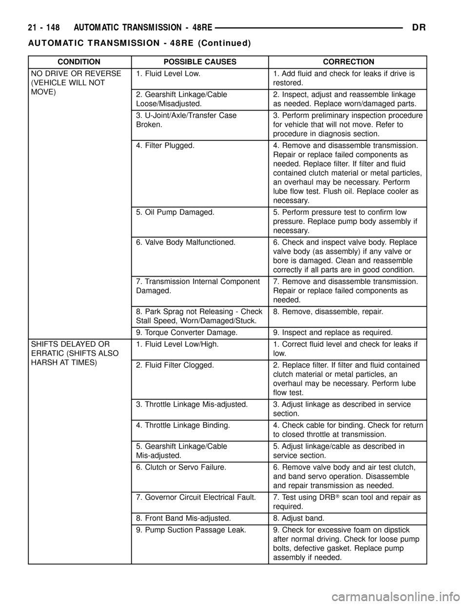
CONDITION POSSIBLE CAUSES CORRECTION
NO DRIVE OR REVERSE
(VEHICLE WILL NOT
MOVE)1. Fluid Level Low. 1. Add fluid and check for leaks if drive is
restored.
2. Gearshift Linkage/Cable
Loose/Misadjusted.2. Inspect, adjust and reassemble linkage
as needed. Replace worn/damaged parts.
3. U-Joint/Axle/Transfer Case
Broken.3. Perform preliminary inspection procedure
for vehicle that will not move. Refer to
procedure in diagnosis section.
4. Filter Plugged. 4. Remove and disassemble transmission.
Repair or replace failed components as
needed. Replace filter. If filter and fluid
contained clutch material or metal particles,
an overhaul may be necessary. Perform
lube flow test. Flush oil. Replace cooler as
necessary.
5. Oil Pump Damaged. 5. Perform pressure test to confirm low
pressure. Replace pump body assembly if
necessary.
6. Valve Body Malfunctioned. 6. Check and inspect valve body. Replace
valve body (as assembly) if any valve or
bore is damaged. Clean and reassemble
correctly if all parts are in good condition.
7. Transmission Internal Component
Damaged.7. Remove and disassemble transmission.
Repair or replace failed components as
needed.
8. Park Sprag not Releasing - Check
Stall Speed, Worn/Damaged/Stuck.8. Remove, disassemble, repair.
9. Torque Converter Damage. 9. Inspect and replace as required.
SHIFTS DELAYED OR
ERRATIC (SHIFTS ALSO
HARSH AT TIMES)1. Fluid Level Low/High. 1. Correct fluid level and check for leaks if
low.
2. Fluid Filter Clogged. 2. Replace filter. If filter and fluid contained
clutch material or metal particles, an
overhaul may be necessary. Perform lube
flow test.
3. Throttle Linkage Mis-adjusted. 3. Adjust linkage as described in service
section.
4. Throttle Linkage Binding. 4. Check cable for binding. Check for return
to closed throttle at transmission.
5. Gearshift Linkage/Cable
Mis-adjusted.5. Adjust linkage/cable as described in
service section.
6. Clutch or Servo Failure. 6. Remove valve body and air test clutch,
and band servo operation. Disassemble
and repair transmission as needed.
7. Governor Circuit Electrical Fault. 7. Test using DRBTscan tool and repair as
required.
8. Front Band Mis-adjusted. 8. Adjust band.
9. Pump Suction Passage Leak. 9. Check for excessive foam on dipstick
after normal driving. Check for loose pump
bolts, defective gasket. Replace pump
assembly if needed.
21 - 148 AUTOMATIC TRANSMISSION - 48REDR
AUTOMATIC TRANSMISSION - 48RE (Continued)
Page 1852 of 2627
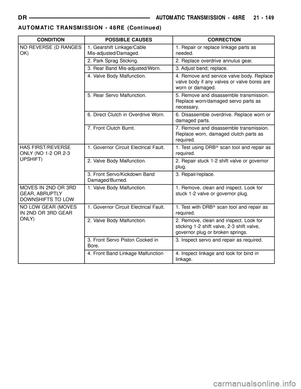
CONDITION POSSIBLE CAUSES CORRECTION
NO REVERSE (D RANGES
OK)1. Gearshift Linkage/Cable
Mis-adjusted/Damaged.1. Repair or replace linkage parts as
needed.
2. Park Sprag Sticking. 2. Replace overdrive annulus gear.
3. Rear Band Mis-adjusted/Worn. 3. Adjust band; replace.
4. Valve Body Malfunction. 4. Remove and service valve body. Replace
valve body if any valves or valve bores are
worn or damaged.
5. Rear Servo Malfunction. 5. Remove and disassemble transmission.
Replace worn/damaged servo parts as
necessary.
6. Direct Clutch in Overdrive Worn. 6. Disassemble overdrive. Replace worn or
damaged parts.
7. Front Clutch Burnt. 7. Remove and disassemble transmission.
Replace worn, damaged clutch parts as
required.
HAS FIRST/REVERSE
ONLY (NO 1-2 OR 2-3
UPSHIFT)1. Governor Circuit Electrical Fault. 1. Test using DRBTscan tool and repair as
required.
2. Valve Body Malfunction. 2. Repair stuck 1-2 shift valve or governor
plug.
3. Front Servo/Kickdown Band
Damaged/Burned.3. Repair/replace.
MOVES IN 2ND OR 3RD
GEAR, ABRUPTLY
DOWNSHIFTS TO LOW1. Valve Body Malfunction. 1. Remove, clean and inspect. Look for
stuck 1-2 valve or governor plug.
NO LOW GEAR (MOVES
IN 2ND OR 3RD GEAR
ONLY)1. Governor Circuit Electrical Fault. 1. Test with DRBTscan tool and repair as
required.
2. Valve Body Malfunction. 2. Remove, clean and inspect. Look for
sticking 1-2 shift valve, 2-3 shift valve,
governor plug or broken springs.
3. Front Servo Piston Cocked in
Bore.3. Inspect servo and repair as required.
4. Front Band Linkage Malfunction 4. Inspect linkage and look for bind in
linkage.
DRAUTOMATIC TRANSMISSION - 48RE 21 - 149
AUTOMATIC TRANSMISSION - 48RE (Continued)