1998 DODGE RAM 1500 servo cable
[x] Cancel search: servo cablePage 708 of 2627

INSTALLATION
(1) Install a new rubber grommet seal into the
washer fluid level switch mounting hole in the
washer reservoir. Always use a new rubber grommet
seal on the reservoir.
(2) Insert the float of the washer fluid level switch
through the rubber grommet seal and into the
washer reservoir. The connector receptacle of the
washer fluid level switch should be pointed upward.
(3) Using hand pressure, press firmly and evenly
on the washer fluid level switch mounting flange
until the barbed nipple is fully seated in the rubber
grommet seal in the washer reservoir mounting hole.
(4) Reconnect the right (except diesel engine) or
left (diesel engine only) headlamp and dash wire har-
ness connector for the washer fluid level switch to
the switch connector receptacle (Fig. 7) or (Fig. 8).
(5) Reconnect the removed washer hose to the
barbed outlet nipple of the washer pump/motor unit.
(6) Refill the washer reservoir with the washer
fluid drained from the reservoir during the removal
procedure.
(7) Reconnect the battery negative cable.
(8) Close and latch the hood.
WASHER HOSES/TUBES
DESCRIPTION
The washer plumbing consists of a small diameter
rubber reservoir washer hose that is routed from the
barbed outlet nipple of the electric washer pump/mo-tor unit on the washer reservoir through a trough
molded into the back of the reservoir above the
washer pump and to the engine compartment washer
hose (Fig. 9). On models equipped with an optional
diesel engine, the reservoir washer hose is routed
through routing clips on the top of the radiator fan
shroud from the washer reservoir on the left side of
the radiator to the engine compartment washer hose
on the right side of the radiator. The engine compart-
ment washer hose is contained within the right head-
lamp and dash wire harness, which is routed through
the engine compartment along the top of the right
front fender wheel house to the dash panel.
The engine compartment washer hose is connected
to the washer reservoir washer hose and to the cowl
plenum washer hose with molded plastic in-line fit-
tings that have a barbed nipple on each end. The
cowl plenum washer hose is routed from the engine
compartment into the cowl plenum area through a
trough formation located near the right end of the
cowl plenum cover/grille panel. The cowl plenum
washer hose is connected to the washer system check
valve/wye fitting on the underside of the cowl plenum
cover/grille panel. The cowl plenum washer hose and
the two washer nozzle hoses are routed through inte-
gral routing clips on the underside of the cowl ple-
num cover/grille panel. The cowl plenum washer hose
is connected to one nipple on the wye fitting and the
two washer nozzle hoses are connected to the other
two wye fitting nipples. The washer nozzle hoses are
then routed along the underside of the cowl plenum
cover/grille panel to the two washer nozzles.
Washer hose is available for service only as roll
stock, which must then be cut to length. The molded
plastic washer hose fittings cannot be repaired. If
these fittings are faulty or damaged, they must be
replaced.
OPERATION
Washer fluid in the washer reservoir is pressurized
and fed by the washer pump/motor through the
washer system plumbing and fittings to the two
washer nozzles. Whenever routing the washer hose
or a wire harness containing a washer hose, it must
be routed away from hot, sharp, or moving parts;
and, sharp bends that might pinch the hose must be
avoided.
WASHER NOZZLE
DESCRIPTION
The two washer nozzles have integral snap fea-
tures and an anti-rotation tab that secure them in
dedicated holes in the cowl plenum cover/grille panel
located near the base of the windshield (Fig. 10). The
Fig. 9 Engine Compartment Washer Hose
1 - RIGHT FENDER
2 - RIGHT HEADLAMP & DASH WIRE HARNESS
3 - ENGINE COMPARTMENT WASHER HOSE (TO COWL
PLENUM)
4 - COWL PLENUM WASHER HOSE
5 - ENGINE COMPARTMENT WASHER HOSE (TO WASHER
RESERVOIR)
DRWIPERS/WASHERS 8R - 11
WASHER FLUID LEVEL SWITCH (Continued)
Page 711 of 2627

inputs and outputs related to the washer pump/mo-
tor unit operation requires the use of a DRBIIItscan
tool. Refer to the appropriate diagnostic information.
REMOVAL
The washer pump/motor unit can be removed from
the washer reservoir without removing the reservoir
from the vehicle.
(1) Unlatch and open the hood.
(2) Disconnect and isolate the battery negative
cable.
(3) Disconnect the washer hose from the barbed
outlet nipple of the washer pump/motor unit and
allow the washer fluid to drain into a clean container
for reuse.
(4) Disconnect the right (except diesel engine) or
left (diesel engine only) headlamp and dash wire har-
ness connector for the washer pump/motor unit from
the motor connector receptacle (Fig. 13).
(5) Firmly grasp the top of the washer pump/motor
housing.
(6) Pull lightly outward on the top of the washer
pump/motor housing away from the washer reservoir
far enough to disengage the snap post on the top of
the motor from the receptacle in the reservoir.(7) Pull the washer pump/motor unit straight out
from the washer reservoir far enough to disengage
the barbed pump inlet nipple from the rubber grom-
met seal in the reservoir.
(8) Disconnect the reservoir washer hose from the
washer pump/motor unit outlet nipple.
(9) Remove washer pump/motor unit from the back
of the washer reservoir.
(10) Remove the rubber grommet seal from the
washer reservoir and discard.
INSTALLATION
(1) Install a new rubber grommet seal into the
washer pump mounting hole in the washer reservoir.
Always use a new rubber grommet seal on the reser-
voir.
(2) Position the barbed inlet nipple of the washer
pump to the rubber grommet seal in the washer res-
ervoir (Fig. 13).
(3) Using hand pressure, press on the washer
pump/motor unit firmly and evenly until the barbed
inlet nipple is fully seated in the rubber grommet
seal in the washer reservoir mounting hole.
(4) Align the washer pump/motor snap post on the
top of the motor housing with the snap post recepta-
cle in the washer reservoir.
(5) Using hand pressure, press firmly and evenly
on the top of washer pump/motor unit until the snap
post snaps into the washer reservoir receptacle.
(6) Reconnect the washer reservoir hose to the
barbed outlet nipple of the washer pump.
(7) Reconnect the right (except diesel engine) or
left (diesel engine only) headlamp and dash wire har-
ness connector for the washer pump/motor unit to
the motor connector receptacle.
(8) Refill the washer reservoir with the washer
fluid drained from the reservoir during the removal
procedure.
(9) Reconnect the battery negative cable.
(10) Close and latch the hood.
WASHER RESERVOIR
DESCRIPTION
Except on models equipped with an optional diesel
engine, the molded plastic washer fluid reservoir is
mounted on the right rearward facing surface of the
cooling module radiator shroud in the engine com-
partment (Fig. 14). On models with the diesel engine,
the molded plastic washer fluid reservoir is mounted
on the rearward facing surface of the left vertical
member of the radiator support in the engine com-
partment. The reservoir is a molded unit constructed
of a translucent plastic that allows the washer fluid
level to be inspected without removing the washer
Fig. 13 Washer Pump/Motor Remove/Install
1 - CONNECTOR RECEPTACLE
2 - SNAP POST
3 - SNAP POST RECEPTACLE
4 - GROMMET SEAL
5 - WASHER FLUID LEVEL SWITCH
6 - WASHER RESERVOIR
7 - INLET NIPPLE
8 - OUTLET NIPPLE
8R - 14 WIPERS/WASHERSDR
WASHER PUMP/MOTOR (Continued)
Page 712 of 2627

reservoir cap. The most visible component of the
washer reservoir is the filler cap unit, which is
secured to and hinges on a hook feature that is inte-
gral to the filler neck near the top of the reservoir.
The bright yellow plastic filler cap snaps over the
filler neck opening and seals the reservoir opening
with an integral rubber gasket. The filler cap is
labeled with an International Control and Display
Symbol icon for ªWindshield Washerº and the text
ªWasher Fluid Onlyº that are molded into it and
highlighted in black against the yellow plastic cap for
visibility.
There are dedicated holes near the bottom of the
rearward facing side of the reservoir provided for the
mounting of the washer pump/motor unit and the
washer fluid level switch. A snap post receptacle
molded into the reservoir allows for mounting of the
washer pump without the use of fasteners. The res-
ervoir also features an integral hose routing trough
on its rearward facing side. Except on models with a
diesel engine, the washer reservoir is secured to the
cooling module radiator shroud with three integral
tabs, two at the bottom and one at the top. The two
bottom tabs are inserted into two slots near the bot-tom of the shroud, while the upper tab slides into an
integral channel-like slot near the top of the shroud.
A molded lock feature on the forward facing surface
of the reservoir engages a molded depression on the
rearward facing surface of the radiator shroud when
the reservoir is fully seated on the shroud, locking
the unit securely in place. On models with a diesel
engine, the washer reservoir is secured with two
screws through integral mounting tabs to the left
vertical member of the radiator support. On many
models, a molded plastic coolant recovery container
or a coolant pressure container must be detached
from the top of the cooling module and moved aside
to access the washer fluid reservoir for service. This
may be accomplished without opening or draining the
engine cooling system.
OPERATION
The washer fluid reservoir provides a secure,
on-vehicle storage location for a large reserve of
washer fluid for operation of the washer system. The
washer reservoir filler neck provides a clearly
marked and readily accessible point from which to
add washer fluid to the reservoir. The washer/pump
motor unit is located in a sump area near the bottom
of the reservoir to be certain that washer fluid will
be available to the pump as the fluid level in the res-
ervoir becomes depleted. The washer pump/motor
unit is mounted in the lowest position in the sump.
The washer fluid level switch is mounted just above
the sump area of the reservoir so that there will be
adequate warning to the vehicle operator that the
washer fluid level is low, well before the washer sys-
tem will no longer operate.
REMOVAL
REMOVAL - EXCEPT DIESEL ENGINE
(1) Unlatch and open the hood.
(2) Disconnect and isolate the battery negative
cable.
(3) Remove the fasteners securing the coolant
recovery container or the coolant pressure container
to the top of the cooling module and move the con-
tainer aside. It is not necessary to open or drain the
engine cooling system. (Refer to 7 - COOLING/EN-
GINE/COOLANT RECOVERY CONTAINER -
REMOVAL) or (Refer to 7 - COOLING/ENGINE/
COOLANT RECOVERY PRESSURE CONTAINER -
REMOVAL).
(4) Disconnect the reservoir washer hose from the
barbed nipple of the inline fitting at the engine com-
partment washer hose in the right headlamp and
dash wire harness and allow the washer fluid to
Fig. 14 Washer Reservoir - except Diesel Engine
1-TOPTAB
2 - HOOK FEATURE
3 - CAP
4 - RESERVOIR
5 - TROUGH
6 - HOSE
7 - LOCK FEATURE
8 - WASHER FLUID LEVEL SWITCH
9 - WASHER PUMP/MOTOR
10 - BOTTOM TAB (2)
DRWIPERS/WASHERS 8R - 15
WASHER RESERVOIR (Continued)
Page 713 of 2627

drain from the reservoir into a clean container for
reuse (Fig. 15).
(5) Disconnect the right headlamp and dash wire
harness connector for the washer fluid level switch
from the switch connector receptacle.
(6) Disconnect the right headlamp and dash wire
harness connector for the washer pump/motor unit
from the motor connector receptacle.
(7) Grasp the bottom of the washer reservoir
firmly with both hands and pull the unit sharply
upward to disengage the locking feature on the
washer reservoir from the depression in the radiator
shroud.
(8) Continue lifting the washer reservoir upward
far enough to disengage the three mounting tabs (one
at the top and two at the bottom) from the channel-
like slot at the top and the two slots at the bottom of
the radiator shroud.
(9) Remove the washer reservoir from the right
side of the engine compartment.REMOVAL - DIESEL ENGINE
(1) Unlatch and open the hood.
(2) Disconnect and isolate the battery negative
cable.
(3) Disengage the reservoir washer hose from the
integral routing clips on the top of the radiator fan
shroud (Fig. 16).
(4) Disconnect the reservoir washer hose from the
barbed nipple of the inline fitting at the engine com-
partment washer hose in the right headlamp and
dash wire harness and allow the washer fluid to
drain from the reservoir into a clean container for
reuse.
(5) Disconnect the left headlamp and dash wire
harness connector for the washer fluid level switch
from the switch connector receptacle.
(6) Disconnect the left headlamp and dash wire
harness connector for the washer pump/motor unit
from the motor connector receptacle.
(7) Remove the two screws that secure the washer
reservoir to the left vertical member of the radiator
support (Fig. 17).
(8) Remove the washer reservoir from the left side
of the engine compartment.
Fig. 15 Washer Reservoir Remove/Install
1-TOPTAB
2 - RADIATOR SHROUD
3 - TOP SLOT
4 - RIGHT HEADLAMP & DASH WIRE HARNESS
5 - ENGINE COMPARTMENT WASHER HOSE
6 - BOTTOM SLOT (2)
7 - RESERVOIR WASHER HOSE
8 - BOTTOM TAB (2)
9 - WASHER FLUID LEVEL SWITCH
10 - WASHER PUMP/MOTOR
11 - WASHER RESERVOIR
12 - LOCK FEATURE
Fig. 16 Washer Reservoir Connections - Diesel
Engine
1 - WIRE HARNESS
2 - WASHER RESERVOIR
3 - WASHER PUMP/MOTOR
4 - WASHER HOSE
5 - WASHER FLUID LEVEL SWITCH
8R - 16 WIPERS/WASHERSDR
WASHER RESERVOIR (Continued)
Page 714 of 2627

INSTALLATION
INSTALLATION - EXCEPT DIESEL ENGINE
(1) Position the washer reservoir into the right
side of the engine compartment.
(2) Align and insert the three mounting tabs (one
at the top and two at the bottom) into the two slots
at the bottom and the channel-like slot at the top of
the radiator shroud (Fig. 15).
(3) Place both hands on the top of the washer res-
ervoir and push the unit downward far enough for
the locking feature on the washer reservoir to snap
into the depression in the radiator shroud.
(4) Reconnect the right headlamp and dash wire
harness connector for the washer pump/motor unit to
the motor connector receptacle.
(5) Reconnect the right headlamp and dash wire
harness connector for the washer fluid level switch to
the switch connector receptacle.
(6) Reconnect the reservoir washer hose to the
barbed nipple of the inline fitting at the engine com-
partment washer hose in the right headlamp and
dash wire harness.
(7) Reposition the coolant recovery container or the
coolant pressure container to the top of the cooling
module and reinstall the fasteners that secure it
there. (Refer to 7 - COOLING/ENGINE/COOLANT
RECOVERY CONTAINER - INSTALLATION) or
(Refer to 7 - COOLING/ENGINE/COOLANT RECOV-
ERY PRESSURE CONTAINER - INSTALLATION).
(8) Refill the washer reservoir with the washer
fluid drained from the reservoir during the removal
procedure.
(9) Reconnect the battery negative cable.
(10) Close and latch the hood.
INSTALLATION - DIESEL ENGINE
(1) Position the washer reservoir into the left side
of the engine compartment (Fig. 17).
(2) Install and tighten the two screws that secure
the washer reservoir to the left vertical member of
the radiator support. Tighten the screws to 10 N´m
(85 in. lbs.).
(3) Reconnect the left headlamp and dash wire
harness connector for the washer pump/motor unit to
the motor connector receptacle (Fig. 16).
(4) Reconnect the left headlamp and dash wire
harness connector for the washer fluid level switch to
the switch connector receptacle.
(5) Reconnect the reservoir washer hose to the
barbed nipple of the inline fitting at the engine com-
partment washer hose in the right headlamp and
dash wire harness.
(6) Engage the reservoir washer hose into the inte-
gral routing clips on the top of the radiator fan
shroud.
(7) Refill the washer reservoir with the washer
fluid drained from the reservoir during the removal
procedure.
(8) Reconnect the battery negative cable.
(9) Close and latch the hood.
WIPER ARM
DESCRIPTION
The wiper arms are the rigid members located
between the wiper pivots that protrude from the cowl
Fig. 17 Washer Reservoir
Remove/Install - Diesel Engine
1 - RESERVOIR WASHER HOSE
2 - RADIATOR SUPPORT
3 - SCREW (2)
4 - WASHER RESERVOIR
Fig. 18 Wiper Arm
1 - HOOK
2 - STRAP
3 - PIVOT END
4 - KEY
5-LATCH
6 - HINGE PIN
7 - TENSION SPRING
8 - CHANNEL
DRWIPERS/WASHERS 8R - 17
WASHER RESERVOIR (Continued)
Page 1160 of 2627
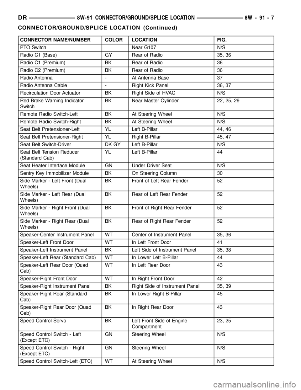
CONNECTOR NAME/NUMBER COLOR LOCATION FIG.
PTO Switch Near G107 N/S
Radio C1 (Base) GY Rear of Radio 35, 36
Radio C1 (Premium) BK Rear of Radio 36
Radio C2 (Premium) BK Rear of Radio 36
Radio Antenna - At Antenna Base 37
Radio Antenna Cable - Right Kick Panel 36, 37
Recirculation Door Actuator BK Right Side of HVAC N/S
Red Brake Warning Indicator
SwitchBK Near Master Cylinder 22, 25, 29
Remote Radio Switch-Left BK At Steering Wheel N/S
Remote Radio Switch-Right BK At Steering Wheel N/S
Seat Belt Pretensioner-Left YL Left B-Pillar 44, 46
Seat Belt Pretensioner-Right YL Right B-Pillar 45, 47
Seat Belt Switch-Driver DK GY Left B-Pillar N/S
Seat Belt Tension Reducer
(Standard Cab)YL Left B-Pillar 44
Seat Heater Interface Module GN Under Driver Seat N/S
Sentry Key Immobilizer Module BK On Steering Column 30
Side Marker - Left Front (Dual
Wheels)BK Front of Left Rear Fender 52
Side Marker - Left Rear (Dual
Wheels)BK Rear of Left Rear Fender 52
Side Marker - Right Front (Dual
Wheels)BK Front of Right Rear Fender 52
Side Marker - Right Rear (Dual
Wheels)BK Rear of Right Rear Fender 52
Speaker-Center Instrument Panel WT Center of Instrument Panel 35, 36
Speaker-Left Front Door WT In Left Front Door 41
Speaker-Left Instrument Panel BK Left Side of Instrument Panel 35, 38
Speaker-Left Rear (Standard Cab) WT In Lower Left B-Pillar 44
Speaker-Left Rear Door (Quad
Cab)WT In Left Rear Door 43
Speaker-Right Front Door WT In Right Front Door 42
Speaker-Right Instrument Panel BK Right Side of Instrument Panel 35, 39
Speaker-Right Rear (Standard
Cab)BK In Lower Right B-Pillar 45
Speaker-Right Rear Door (Quad
Cab)BK In Right Rear Door 43
Speed Control Servo BK Left Front Side of Engine
Compartment23, 25
Speed Control Switch - Left
(Except ETC)GN Steering Wheel N/S
Speed Control Switch - Right
(Except ETC)GN Steering Wheel N/S
Speed Control Switch-Left (ETC) WT At Steering Wheel N/S
DR8W-91 CONNECTOR/GROUND/SPLICE LOCATION 8W - 91 - 7
CONNECTOR/GROUND/SPLICE LOCATION (Continued)
Page 1296 of 2627

(1) Start the engine.
(2) Spray a small stream of water (spray bottle) at
the suspected leak area.
(3) If engine RPM'S change, the area of the sus-
pected leak has been found.
(4) Repair as required.
REMOVAL
(1) Disconnect negative cable from battery.
(2) Remove resonator assembly and air inlet hose.
(3) Disconnect throttle and speed control cables.
(4) Disconnect electrical connectors for the follow-
ing components: Refer to FUEL SYSTEM for compo-
nent locations.
²Manifold Absolute Pressure (MAP) Sensor
²Intake Air Temperature (IAT) Sensor
²Throttle Position (TPS) Sensor
²Coolant Temperature (CTS) Sensor
²Idle Air Control (IAC) Motor
(5) Disconnect vapor purge hose, brake booster
hose, speed control servo hose, positive crankcase
ventilation (PCV) hose.
(6) Disconnect generator electrical connections.
(7) Disconnect air conditioning compressor electri-
cal connections.
(8) Disconnect left and right radio suppressor
straps.
(9) Disconnect and remove ignition coil towers.
(10) Remove top oil dipstick tube retaining bolt
and ground strap.
(11) Bleed fuel system (Refer to 14 - FUEL SYS-
TEM/FUEL DELIVERY - STANDARD PROCE-
DURE).
(12) Remove fuel rail.
(13) Remove throttle body assembly and mounting
bracket.
(14) Drain cooling system below coolant tempera-
ture level (Refer to 7 - COOLING - STANDARD
PROCEDURE).
(15) Remove the heater hoses from the engine
front cover and the heater core.
(16) Unclip and remove heater hoses and tubes
from intake manifold.
(17) Remove coolant temperature sensor (Refer to
7 - COOLING/ENGINE/ENGINE COOLANT TEMP
SENSOR - REMOVAL).
(18) Remove intake manifold retaining fasteners in
reverse order of tightening sequence.
(19) Remove intake manifold.
INSTALLATION
(1) Install intake manifold gaskets.
(2) Install intake manifold.
(3) Install intake manifold retaining bolts and
tighten in sequence shown in to 12 N´m (105 in. lbs.)
(Fig. 89).(4) Install left and right radio suppressor straps.
(5) Install throttle body assembly.
(6) Connect throttle cable and speed control cable
to throttle body.
(7) Install fuel rail.
(8) Install ignition coil towers.
(9) Position and install heater hoses and tubes
onto intake manifold.
(10) Install the heater hoses to the heater core and
engine front cover.
(11) Connect electrical connectors for the following
components:
²Manifold Absolute Pressure (MAP) Sensor
²Intake Air Temperature (IAT) Sensor
²Throttle Position (TPS) Sensor
²Coolant Temperature (CTS) Sensor
²Idle Air Control (IAC) Motor
²Ignition coil towers
²Fuel injectors
(12) Install top oil dipstick tube retaining bolt and
ground strap.
(13) Connect generator electrical connections.
(14) Connect Vapor purge hose, Brake booster
hose, Speed control servo hose, Positive crankcase
ventilation (PCV) hose.
(15) Fill cooling system (Refer to 7 - COOLING -
STANDARD PROCEDURE).
(16) Install resonator assembly and air inlet hose.
(17) Connect negative cable to battery.
Fig. 89 Intake Manifold Tightening Sequence
DRENGINE - 3.7L 9 - 73
INTAKE MANIFOLD (Continued)
Page 1495 of 2627
(6) Remove the wooden dowel rods and rubber
bands from the tappets.
(7) Lubricate the push rods with engine oil and
install in their original location.Verify that they
are seated in the tappets.
(8) Lubricate the valve tips with engine oil and
install the crossheads in their original locations.
(9) Lubricate the crossheads and push rod sockets
with engine oil and install the rocker arms and ped-
estals in their original locations. Tighten bolts to 36
N´m (27 ft. lbs.) torque.
(10)Verify valve lash adjustment (Refer to 9 -
ENGINE/CYLINDER HEAD/INTAKE/EXHAUST
VALVES & SEATS - STANDARD PROCEDURE).
(11) Install the cylinder head cover and reusable
gasket (Refer to 9 - ENGINE/CYLINDER HEAD/
CYLINDER HEAD COVER(S) - INSTALLATION).
(12) Install gear housing cover (Refer to 9 -
ENGINE/VALVE TIMING/GEAR HOUSING COVER
- INSTALLATION). Install front crankshaft dust
seal.
(13) Install the crankshaft damper with the speed
indicator ring (Refer to 9 - ENGINE/ENGINE
BLOCK/VIBRATION DAMPER - INSTALLATION).
(14) Install the fan support/hub assembly Refer to
(Refer to 7 - COOLING/ENGINE/RADIATOR FAN -
INSTALLATION).
(15) Install the power steering pump.
(16) Install accessory drive belt tensioner. Torque
bolt to 43 Nm (32 ft. lbs.).
(17) Install the accessory drive belt (Refer to 7 -
COOLING/ACCESSORY DRIVE/DRIVE BELTS -
INSTALLATION).
(18) Install the charge air cooler (with a/c con-
denser and auxiliary transmission oil cooler, if
equipped) and tighten the mounting bolts to 2 N´m
(17 in. lbs.) torque.
(19) Connect charge air cooler inlet and outlet
pipes. Tighten clamps to 11 N´m (95 in. lbs.) torque.
(20) Install the radiator upper support panel.
(21) Close radiator petcock and lower the radiator
into the engine compartment. Tighten the mounting
bolts to 11 N´m (95 in. lbs.) torque.
(22) Raise vehicle on hoist.
(23) Connect radiator lower hose and install
clamp.
(24) Connect transmission auxiliary oil cooler lines
(if equipped).
(25) Lower vehicle.
(26) Install the fan shroud and tighten the mount-
ing screws to 6 N´m (50 in. lbs.) torque.
(27) Install the electronically controlled viscous
fan/drive assembly. Connect harness connector.(Refer
to 7 - COOLING/ENGINE/RADIATOR FAN -
INSTALLATION).(28) Install the coolant recovery and windshield
washer fluid reservoirs to the fan shroud.
(29) Connect the coolant recovery hose to the radi-
ator filler neck.
(30) Add engine coolant (Refer to 7 - COOLING -
STANDARD PROCEDURE).
(31) Charge A/C system with refrigerant (if A/C
equipped) (Refer to 24 - HEATING & AIR CONDI-
TIONING/PLUMBING - STANDARD PROCEDURE).
(32) Connect the battery negative cables.
(33) Start engine and check for engine oil and cool-
ant leaks.
CONNECTING ROD BEARINGS
STANDARD PROCEDURE - CONNECTING ROD
BEARING AND CRANKSHAFT JOURNAL
CLEARANCE
(1) Measure the connecting rod bore with bearings
removedand the bolts tightened to 100 N´m (73 ft.
lbs.) torque..
(2) Measure the connecting rod bore with the bear-
ingsinstalledand the bolts tightened to 100 N´m
(73 ft. lbs.) torque.
Measure within 20É arc from each side of the part-
ing line. Also measure 90É from parting line.
Record the smallest and largest diameter.
Measure the diameter of the rod journal at the
location shown (Fig. 63). Calculate the average diam-
eter for each side of the journal.
Determine minimum bearing clearance by calculat-
ing the differance between the smallest connecting
rod bore diameter with the bearing installed and the
average diameter for each side of the crankshaft jour-
nal.
Determine the maximum bearing clearance by cal-
culating the difference between the largest connect-
ing rod bore diameter and the average diameter with
the bearing installed for each side of the crankshaft
journal.
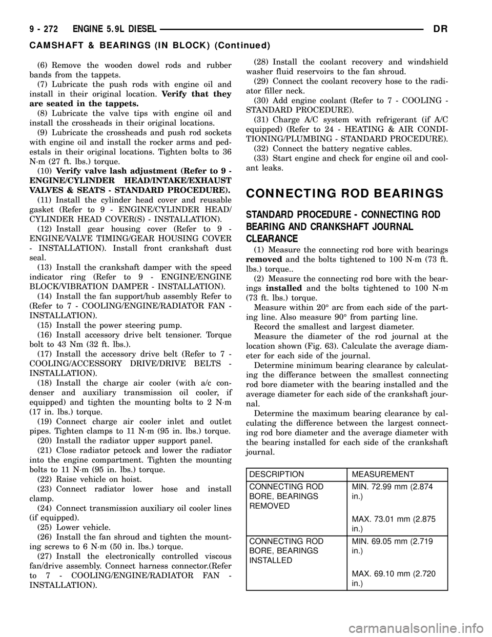
DESCRIPTION MEASUREMENT
CONNECTING ROD
BORE, BEARINGS
REMOVEDMIN. 72.99 mm (2.874
in.)
MAX. 73.01 mm (2.875
in.)
CONNECTING ROD
BORE, BEARINGS
INSTALLEDMIN. 69.05 mm (2.719
in.)
MAX. 69.10 mm (2.720
in.)
9 - 272 ENGINE 5.9L DIESELDR
CAMSHAFT & BEARINGS (IN BLOCK) (Continued)