1998 DODGE RAM 1500 radiator cap
[x] Cancel search: radiator capPage 1245 of 2627
²Excessive steam (white smoke) emitting from
exhaust
²Coolant foaming
CYLINDER-TO-CYLINDER LEAKAGE TEST
To determine if an engine cylinder head gasket is
leaking between adjacent cylinders, follow the proce-
dures in Cylinder Compression Pressure Test (Refer
to 9 - ENGINE - DIAGNOSIS AND TESTING). An
engine cylinder head gasket leaking between adja-
cent cylinders will result in approximately a 50 - 70%
reduction in compression pressure.
CYLINDER-TO-WATER JACKET LEAKAGE TEST
WARNING: USE EXTREME CAUTION WHEN THE
ENGINE IS OPERATING WITH COOLANT PRES-
SURE CAP REMOVED.
VISUAL TEST METHOD
With the engine cool, remove the coolant pressure
cap. Start the engine and allow it to warm up until
thermostat opens.
If a large combustion/compression pressure leak
exists, bubbles will be visible in the coolant.
COOLING SYSTEM TESTER METHOD
WARNING: WITH COOLING SYSTEM TESTER IN
PLACE, PRESSURE WILL BUILD UP FAST. EXCES-
SIVE PRESSURE BUILT UP, BY CONTINUOUS
ENGINE OPERATION, MUST BE RELEASED TO A
SAFE PRESSURE POINT. NEVER PERMIT PRES-
SURE TO EXCEED 138 kPa (20 psi).
Install Cooling System Tester 7700 or equivalent to
pressure cap neck. Start the engine and observe the
tester's pressure gauge. If gauge pulsates with every
power stroke of a cylinder a combustion pressure
leak is evident.
CHEMICAL TEST METHOD
Combustion leaks into the cooling system can also
be checked by using Bloc-Chek Kit C-3685-A or
equivalent. Perform test following the procedures
supplied with the tool kit.
REMOVAL
(1) Disconnect the negative cable from the battery.
(2) Raise the vehicle on a hoist.
(3) Disconnect the exhaust pipe at the left side
exhaust manifold.
(4) Drain the engine coolant(Refer to 7 - COOL-
ING - STANDARD PROCEDURE).
(5) Lower the vehicle.(6) Remove the intake manifold(Refer to 9 -
ENGINE/MANIFOLDS/INTAKE MANIFOLD -
REMOVAL).
(7) Remove the master cylinder and booster assem-
bly(Refer to 5 - BRAKES/HYDRAULIC/MECHANI-
CAL/POWER BRAKE BOOSTER - REMOVAL).
(8) Remove the cylinder head cover(Refer to 9 -
ENGINE/CYLINDER HEAD/CYLINDER HEAD
COVER(S) - REMOVAL).
(9) Remove the fan shroud and fan blade assem-
bly(Refer to 7 - COOLING/ENGINE/RADIATOR FAN
- REMOVAL).
(10) Remove accessory drive belt(Refer to 7 -
COOLING/ACCESSORY DRIVE/DRIVE BELTS -
REMOVAL).
(11) Remove the power steering pump and set
aside.
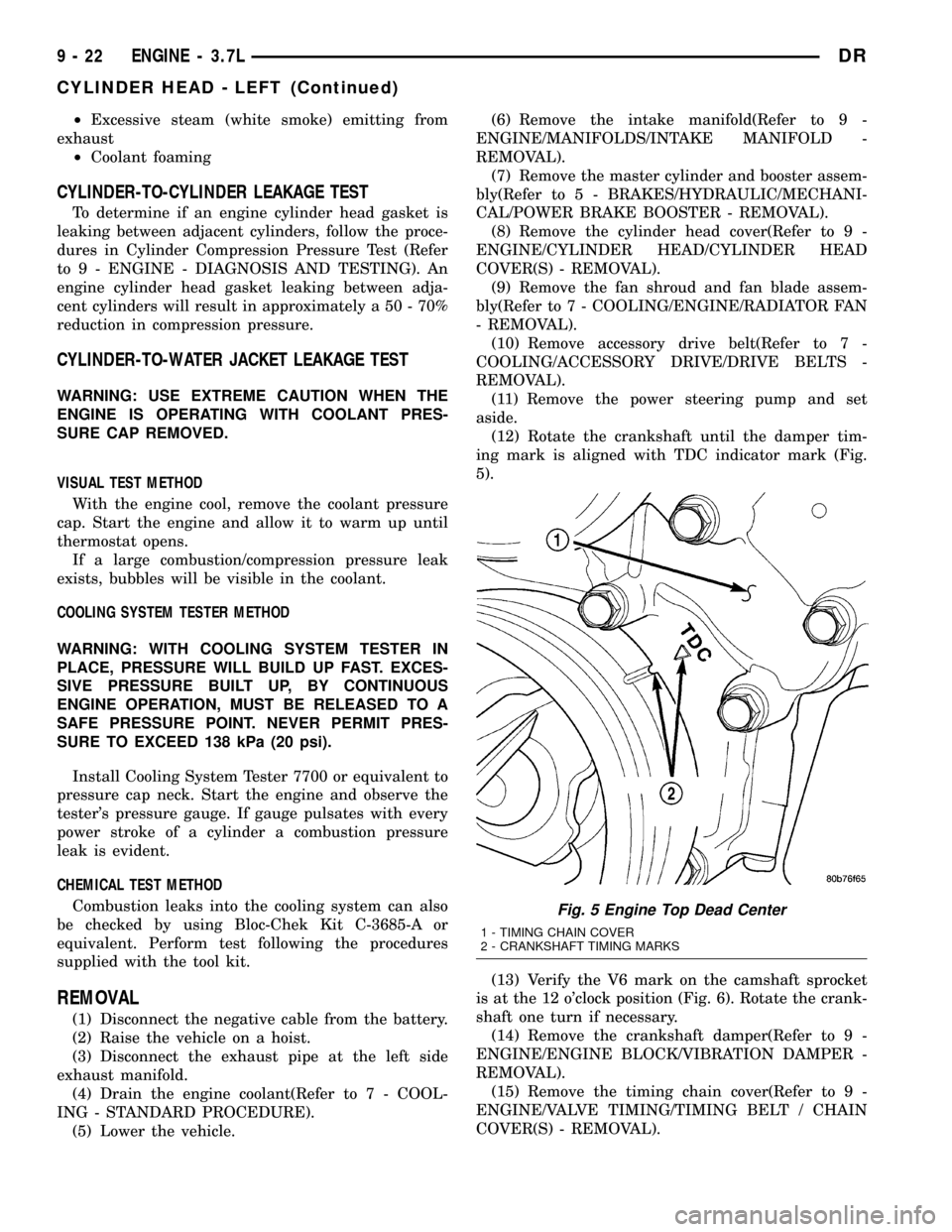
(12) Rotate the crankshaft until the damper tim-
ing mark is aligned with TDC indicator mark (Fig.
5).
(13) Verify the V6 mark on the camshaft sprocket
is at the 12 o'clock position (Fig. 6). Rotate the crank-
shaft one turn if necessary.
(14) Remove the crankshaft damper(Refer to 9 -
ENGINE/ENGINE BLOCK/VIBRATION DAMPER -
REMOVAL).
(15) Remove the timing chain cover(Refer to 9 -
ENGINE/VALVE TIMING/TIMING BELT / CHAIN
COVER(S) - REMOVAL).
Fig. 5 Engine Top Dead Center
1 - TIMING CHAIN COVER
2 - CRANKSHAFT TIMING MARKS
9 - 22 ENGINE - 3.7LDR
CYLINDER HEAD - LEFT (Continued)
Page 1316 of 2627
DIAGNOSIS AND TESTING - CYLINDER
COMPRESSION PRESSURE
The results of a cylinder compression pressure test
can be utilized to diagnose several engine malfunc-
tions.
Ensure the battery is completely charged and the
engine starter motor is in good operating condition.
Otherwise the indicated compression pressures may
not be valid for diagnosis purposes.
(1) Clean the spark plug recesses with compressed
air.
(2) Remove the spark plugs.
(3) Disable the fuel system (Refer to 14 - FUEL
SYSTEM/FUEL DELIVERY - DESCRIPTION).
(4) Remove the ASD relay (Refer to 8 - ELECTRI-
CAL/IGNITION CONTROL/AUTO SHUT DOWN
RELAY - REMOVAL).
(5) Insert a compression pressure gauge and rotate
the engine with the engine starter motor for three
revolutions.
(6)
Record the compression pressure on the 3rd revo-
lution. Continue the test for the remaining cylinders.
(7) (Refer to 9 - ENGINE - SPECIFICATIONS) for
the correct engine compression pressures.
DIAGNOSIS AND TESTING - CYLINDER
COMBUSTION PRESSURE LEAKAGE
The combustion pressure leakage test provides an
accurate means for determining engine condition.
Combustion pressure leakage testing will detect:
²
Exhaust and intake valve leaks (improper seating).
²Leaks between adjacent cylinders or into water
jacket.
²Any causes for combustion/compression pressure
loss.
(1) Check the coolant level and fill as required. DO
NOT install the radiator cap.
(2) Start and operate the engine until it attains
normal operating temperature, then turn the engine
OFF.
(3) Remove the spark plugs.
(4) Remove the oil filler cap.
(5) Remove the air cleaner hose.
(6) Calibrate the tester according to the manufac-
turer's instructions. The shop air source for testing
should maintain 483 kPa (70 psi) minimum, 1,379
kPa (200 psi) maximum and 552 kPa (80 psi) recom-
mended.
(7) Perform the test procedures on each cylinder
according to the tester manufacturer's instructions.
Set piston of cylinder to be tested at TDC compres-
sion,While testing, listen for pressurized air escaping
through the throttle body, tailpipe and oil filler cap
opening. Check for bubbles in the radiator coolant.
All gauge pressure indications should be equal,
with no more than 25% leakage.
FOR EXAMPLE:At 552 kPa (80 psi) input pres-
sure, a minimum of 414 kPa (60 psi) should be main-
tained in the cylinder.
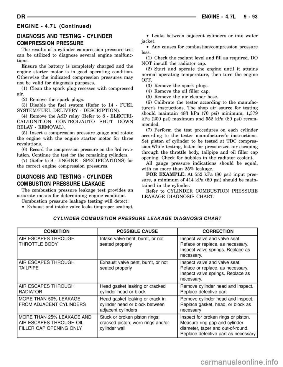
Refer to CYLINDER COMBUSTION PRESSURE
LEAKAGE DIAGNOSIS CHART.
CYLINDER COMBUSTION PRESSURE LEAKAGE DIAGNOSIS CHART
CONDITION POSSIBLE CAUSE CORRECTION
AIR ESCAPES THROUGH
THROTTLE BODYIntake valve bent, burnt, or not
seated properlyInspect valve and valve seat.
Reface or replace, as necessary.
Inspect valve springs. Replace as
necessary.
AIR ESCAPES THROUGH
TAILPIPEExhaust valve bent, burnt, or not
seated properlyInspect valve and valve seat.
Reface or replace, as necessary.
Inspect valve springs. Replace as
necessary.
AIR ESCAPES THROUGH
RADIATORHead gasket leaking or cracked
cylinder head or blockRemove cylinder head and inspect.
Replace defective part
MORE THAN 50% LEAKAGE
FROM ADJACENT CYLINDERSHead gasket leaking or crack in
cylinder head or block between
adjacent cylindersRemove cylinder head and inspect.
Replace gasket, head, or block as
necessary
MORE THAN 25% LEAKAGE AND
AIR ESCAPES THROUGH OIL
FILLER CAP OPENING ONLYStuck or broken piston rings;
cracked piston; worn rings and/or
cylinder wallInspect for broken rings or piston.
Measure ring gap and cylinder
diameter, taper and out-of-round.
Replace defective part as necessary
DRENGINE - 4.7L 9 - 93
ENGINE - 4.7L (Continued)
Page 1409 of 2627
DIAGNOSIS AND TESTING - CYLINDER
COMPRESSION PRESSURE
The results of a cylinder compression pressure test
can be utilized to diagnose several engine malfunc-
tions.
Ensure the battery is completely charged and the
engine starter motor is in good operating condition.
Otherwise the indicated compression pressures may
not be valid for diagnosis purposes.
(1) Clean the spark plug recesses with compressed
air.
(2) Remove the spark plugs.
(3) Disable the fuel system (Refer to 14 - FUEL
SYSTEM/FUEL DELIVERY - DESCRIPTION).
(4) Remove the ASD relay (Refer to 8 - ELECTRI-
CAL/IGNITION CONTROL/AUTO SHUT DOWN
RELAY - REMOVAL).
(5) Insert a compression pressure gauge and rotate
the engine with the engine starter motor for three
revolutions.
(6) Record the compression pressure on the 3rd
revolution. Continue the test for the remaining cylin-
ders.
(7) (Refer to 9 - ENGINE - SPECIFICATIONS) for
the correct engine compression pressures.
DIAGNOSIS AND TESTING - CYLINDER
COMBUSTION PRESSURE LEAKAGE
The combustion pressure leakage test provides an
accurate means for determining engine condition.
Combustion pressure leakage testing will detect:
²Exhaust and intake valve leaks (improper seat-
ing).²Leaks between adjacent cylinders or into water
jacket.
²Any causes for combustion/compression pressure
loss.
(1) Check the coolant level and fill as required. DO
NOT install the radiator cap.
(2) Start and operate the engine until it attains
normal operating temperature, then turn the engine
OFF.
(3) Remove the spark plugs.
(4) Remove the oil filler cap.
(5) Remove the air cleaner hose.
(6) Calibrate the tester according to the manufac-
turer's instructions. The shop air source for testing
should maintain 483 kPa (70 psi) minimum, 1,379
kPa (200 psi) maximum and 552 kPa (80 psi) recom-
mended.
(7) Perform the test procedures on each cylinder
according to the tester manufacturer's instructions.
Set piston of cylinder to be tested at TDC compres-
sion,While testing, listen for pressurized air escaping
through the throttle body, tailpipe and oil filler cap
opening. Check for bubbles in the radiator coolant.
All gauge pressure indications should be equal,
with no more than 25% leakage.
FOR EXAMPLE:At 552 kPa (80 psi) input pres-
sure, a minimum of 414 kPa (60 psi) should be main-
tained in the cylinder.
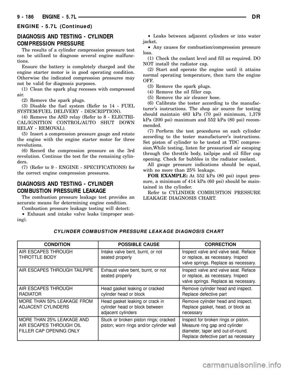
Refer to CYLINDER COMBUSTION PRESSURE
LEAKAGE DIAGNOSIS CHART.
CYLINDER COMBUSTION PRESSURE LEAKAGE DIAGNOSIS CHART
CONDITION POSSIBLE CAUSE CORRECTION
AIR ESCAPES THROUGH
THROTTLE BODYIntake valve bent, burnt, or not
seated properlyInspect valve and valve seat. Reface
or replace, as necessary. Inspect
valve springs. Replace as necessary.
AIR ESCAPES THROUGH TAILPIPE Exhaust valve bent, burnt, or not
seated properlyInspect valve and valve seat. Reface
or replace, as necessary. Inspect
valve springs. Replace as necessary.
AIR ESCAPES THROUGH
RADIATORHead gasket leaking or cracked
cylinder head or blockRemove cylinder head and inspect.
Replace defective part
MORE THAN 50% LEAKAGE FROM
ADJACENT CYLINDERSHead gasket leaking or crack in
cylinder head or block between
adjacent cylindersRemove cylinder head and inspect.
Replace gasket, head, or block as
necessary
MORE THAN 25% LEAKAGE AND
AIR ESCAPES THROUGH OIL
FILLER CAP OPENING ONLYStuck or broken piston rings; cracked
piston; worn rings and/or cylinder wallInspect for broken rings or piston.
Measure ring gap and cylinder
diameter, taper and out-of-round.
Replace defective part as necessary
9 - 186 ENGINE - 5.7LDR
ENGINE - 5.7L (Continued)
Page 1428 of 2627
ENGINE BLOCK
CLEANING
Thoroughly clean the oil pan and engine block gas-
ket surfaces.
Use compressed air to clean out:
²The galley at the oil filter adaptor hole.
²The front and rear oil galley holes.
²The feed holes for the crankshaft main bearings.
Once the block has been completely cleaned, apply
Loctite PST pipe sealant with Teflon 592 to the
threads of the front and rear oil galley plugs. Tighten
the 1/4 inch NPT plugs to 20 N´m (177 in. lbs.)
torque. Tighten the 3/8 inch NPT plugs to 27 N´m
(240 in. lbs.) torque.
INSPECTION
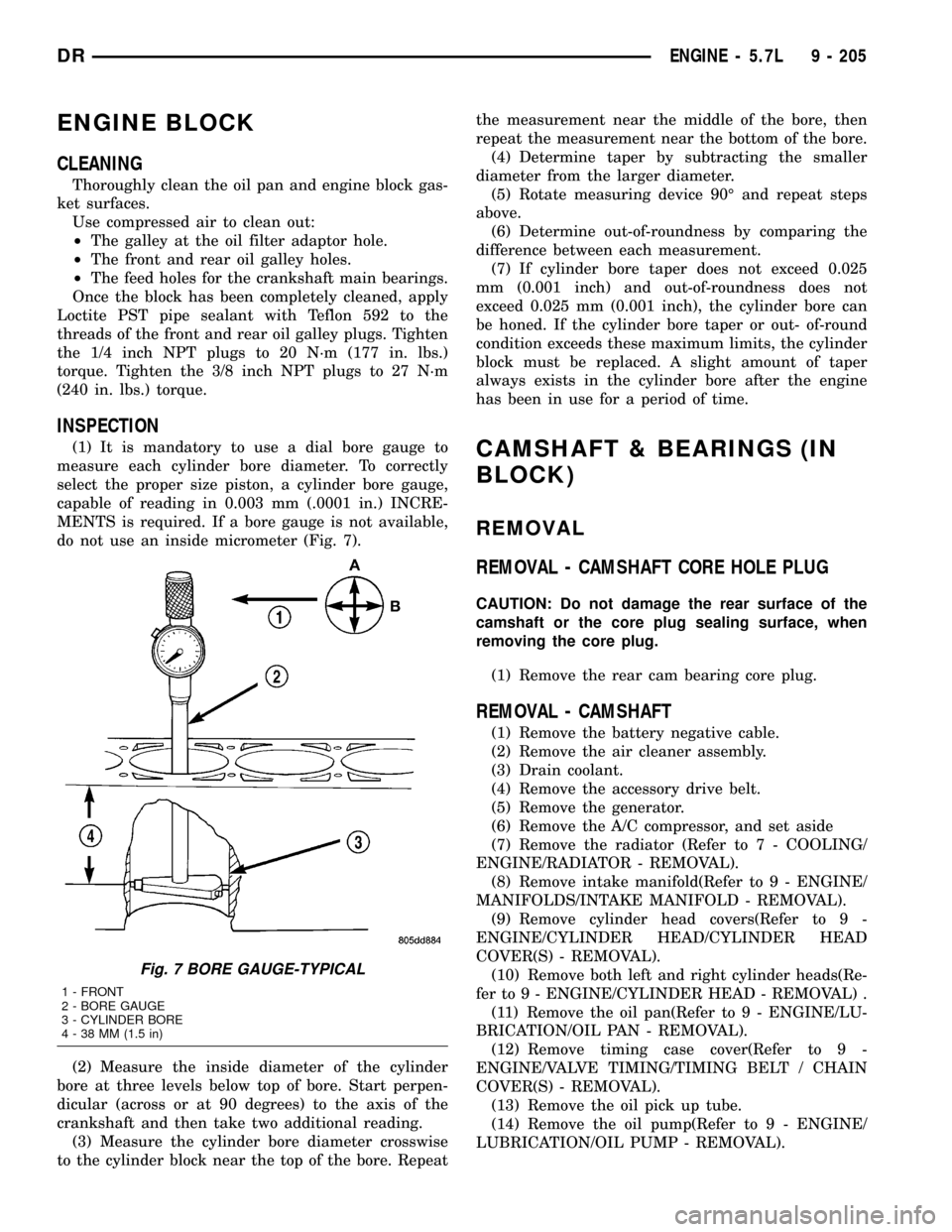
(1) It is mandatory to use a dial bore gauge to
measure each cylinder bore diameter. To correctly
select the proper size piston, a cylinder bore gauge,
capable of reading in 0.003 mm (.0001 in.) INCRE-
MENTS is required. If a bore gauge is not available,
do not use an inside micrometer (Fig. 7).
(2) Measure the inside diameter of the cylinder
bore at three levels below top of bore. Start perpen-
dicular (across or at 90 degrees) to the axis of the
crankshaft and then take two additional reading.
(3) Measure the cylinder bore diameter crosswise
to the cylinder block near the top of the bore. Repeatthe measurement near the middle of the bore, then
repeat the measurement near the bottom of the bore.
(4) Determine taper by subtracting the smaller
diameter from the larger diameter.
(5) Rotate measuring device 90É and repeat steps
above.
(6) Determine out-of-roundness by comparing the
difference between each measurement.
(7) If cylinder bore taper does not exceed 0.025
mm (0.001 inch) and out-of-roundness does not
exceed 0.025 mm (0.001 inch), the cylinder bore can
be honed. If the cylinder bore taper or out- of-round
condition exceeds these maximum limits, the cylinder
block must be replaced. A slight amount of taper
always exists in the cylinder bore after the engine
has been in use for a period of time.CAMSHAFT & BEARINGS (IN
BLOCK)
REMOVAL
REMOVAL - CAMSHAFT CORE HOLE PLUG
CAUTION: Do not damage the rear surface of the
camshaft or the core plug sealing surface, when
removing the core plug.
(1) Remove the rear cam bearing core plug.
REMOVAL - CAMSHAFT
(1) Remove the battery negative cable.
(2) Remove the air cleaner assembly.
(3) Drain coolant.
(4) Remove the accessory drive belt.
(5) Remove the generator.
(6) Remove the A/C compressor, and set aside
(7) Remove the radiator (Refer to 7 - COOLING/
ENGINE/RADIATOR - REMOVAL).
(8) Remove intake manifold(Refer to 9 - ENGINE/
MANIFOLDS/INTAKE MANIFOLD - REMOVAL).
(9) Remove cylinder head covers(Refer to 9 -
ENGINE/CYLINDER HEAD/CYLINDER HEAD
COVER(S) - REMOVAL).
(10) Remove both left and right cylinder heads(Re-
fer to 9 - ENGINE/CYLINDER HEAD - REMOVAL) .
(11) Remove the oil pan(Refer to 9 - ENGINE/LU-
BRICATION/OIL PAN - REMOVAL).
(12) Remove timing case cover(Refer to 9 -
ENGINE/VALVE TIMING/TIMING BELT / CHAIN
COVER(S) - REMOVAL).
(13) Remove the oil pick up tube.
(14) Remove the oil pump(Refer to 9 - ENGINE/
LUBRICATION/OIL PUMP - REMOVAL).
Fig. 7 BORE GAUGE-TYPICAL
1 - FRONT
2 - BORE GAUGE
3 - CYLINDER BORE
4 - 38 MM (1.5 in)
DRENGINE - 5.7L 9 - 205
Page 1429 of 2627
(15) Remove timing chain(Refer to 9 - ENGINE/
VALVE TIMING/TIMING BELT/CHAIN AND
SPROCKETS - REMOVAL).
(16) Remove camshaft tensioner/thrust plate
assembly.
NOTE: Identify tappets to ensure installation in orig-
inal location.
(17) Remove the retainer assembly and tappets.
(18) Install a long bolt into front of camshaft to aid
in removal of the camshaft. Remove camshaft, being
careful not to damage cam bearings with the cam
lobes.
INSPECTION
(1) The cam bearings are not serviceable. Do not
attempt to replace cam bearings for any reason.
INSTALLATION
INSTALLATION - CAMSHAFT CORE HOLE PLUG
CAUTION: The new core hole plug must be installed
to the proper depth or camshaft damage could
develope. The plug must be installed squarely in
the bore.
(1) Install a new core hole plug at the rear of cam-
shaft, using special tool # 9048. Clean plug and apply
mopartlock and seal adhesive to the edge of the
plug, before installing. The plug must be installed to
a depth of+/-0.25mm from the end of the machined
bevel, that is the end of the bevel that is closest to
the cam bearing.
INSTALLATION - CAMSHAFT
(1) Lubricate camshaft lobes and camshaft bearing
journals and insert the camshaft
(2) Install camshaft Tensioner plate assembly.
Tighten bolts to 28 N´m (250 in. lbs.) torque.
(3) Install timing chain and sprockets(Refer to 9 -
ENGINE/VALVE TIMING/TIMING BELT/CHAIN
AND SPROCKETS - INSTALLATION) .
(4) Measure camshaft end play(Refer to 9 -
ENGINE - SPECIFICATIONS). If not within limits
install a new thrust plate.
(5) Install the oil pump(Refer to 9 - ENGINE/LU-
BRICATION/OIL PUMP - INSTALLATION).
(6) Install the oil pick up tube.
(7) Each tappet reused must be installed in the
same position from which it was removed.When
camshaft is replaced, all of the tappets must be
replaced.(8) Install the tappets and retainer assembly(Refer
to 9 - ENGINE/ENGINE BLOCK/HYDRAULIC LIFT-
ERS (CAM IN BLOCK) - INSTALLATION).
(9) Install both left and right cylinder heads(Refer
to 9 - ENGINE/CYLINDER HEAD - INSTALLA-
TION) .
(10) Install pushrods
(11) Install rocker arms(Refer to 9 - ENGINE/CYL-
INDER HEAD/ROCKER ARM / ADJUSTER ASSY -
INSTALLATION).
(12) Install timing case cover(Refer to 9 -
ENGINE/VALVE TIMING/TIMING BELT / CHAIN
COVER(S) - INSTALLATION).
(13) Install the oil pan(Refer to 9 - ENGINE/LU-
BRICATION/OIL PAN - INSTALLATION).
(14) Install cylinder head covers(Refer to 9 -
ENGINE/CYLINDER HEAD/CYLINDER HEAD
COVER(S) - INSTALLATION).
(15) Install intake manifold(Refer to 9 - ENGINE/
MANIFOLDS/INTAKE MANIFOLD - INSTALLA-
TION).
(16) Install the A/C compressor, and set aside
(17) Install the generator.
(18) Install the accessory drive belt.
(19) Install the radiator (Refer to 7 - COOLING/
ENGINE/RADIATOR - INSTALLATION).
(20) Install the air cleaner assembly.
(21) Install the battery negative cable.
(22) Refill coolant.
(23) Refill engine oil.
(24) Start engine and check for leaks.
CRANKSHAFT
REMOVAL
(1) Remove the vibration damper (Refer to 9 -
ENGINE/ENGINE BLOCK/VIBRATION DAMPER -
REMOVAL).
(2) Remove the oil pan(Refer to 9 - ENGINE/LU-
BRICATION/OIL PAN - REMOVAL).
(3) Remove the oil pump pickup.
(4) Remove the windage tray/oil pan gasket.
(5) Remove the timing chain cover(Refer to 9 -
ENGINE/VALVE TIMING/TIMING BELT / CHAIN
COVER(S) - REMOVAL).
(6) Remove the oil pump(Refer to 9 - ENGINE/LU-
BRICATION/OIL PUMP - REMOVAL).
(7) Remove the timing drive(Refer to 9 - ENGINE/
VALVE TIMING/TIMING BELT/CHAIN AND
SPROCKETS - REMOVAL).
(8) Identify rod bearing caps before removal.
Remove rod bearing caps with bearings.
(9) Identify main bearing caps before removal.
Remove main bearing caps and bearings one at a
time.
9 - 206 ENGINE - 5.7LDR
CAMSHAFT & BEARINGS (IN BLOCK) (Continued)
Page 1466 of 2627
(8) Replace injector o-ring and sealing washer on
injectors #5 and #6. Install injectors and torque using
the following steps:
²Step 1ÐInstall injector hold-down capscrews
and torque to 5 N´m (44 in. lbs.) torque.
²Step 2ÐLoosen injector hold-down capscrews.
²Step 3ÐInstall HPC connector tube and nut.
Torque nut to 15 N´m (11 ft. lbs.) torque.
²Step 4ÐTorque injector hold-down capscrews to
10 N´m (89 in. lbs.) torque.
²Step 5ÐTorque HPC connector tube nut to 50
N´m (37 ft. lbs.) torque.
(9) Install #5 and #6 high pressure fuel lines. Fol-
low correct torque sequence per section 14. Torque
fuel line fittings to 30 N-m (22 ft-lb). Torque brace
capscrew to 24 N-m (18 ft-lb).
(10) Install rear engine lift bracket. Torque to 77
N-m (57 ft-lb).
(11) Install push tubes, rocker arms, and pedestals
for cylinders #4, #5, and #6. Torque the mounting
bolts to 36 N-m (27 ft-lbs).
(12) Reset valve lash on cylinders #4, #5, and #6.
Torque adjusting nuts to 24 N-m (18 ft-lbs).
(13) Install cylinder head cover. Torque to 24 N-m
(18 ft-lbs).(Refer to 9 - ENGINE/CYLINDER HEAD -
INSTALLATION).
(14) Connect breather tube and lube oil drain tube
to breather housing cover. Install breather housing.
Torque capscrews to 24 N-m (18 ft-lbs)
(15) Connect fuel supply and return hoses.
(16) Connect ECM ground to hydroform screw.
Connect ECM power connector.
(17) Install the APPS cable(s) to the APPS. Install
the throttle linkage cover.
(18) Install the power steering pump.
(19) Install the damper and speed indicator ring.
Torque to 40 N-m (30 ft-lb) plus 60 degrees.
(20) Connect the engine block heater connection.
(21) Connect the A/C compressor and pressure sen-
sor connectors
(22) Install the charge air cooler and a/c condenser
(if equipped). Install and tighten the charge air
cooler mounting bolts to 2 N-m (17 in-lbs).
(23) Connect the charge air cooler piping. Torque
all clamps to 8 N-m (72 in-lbs).
(24) Connect the a/c refrigerant lines to the a/c
condenser (if equipped).
(25) Install the radiator upper support panel.
(26) Install radiator.
(27) Connect the transmission quick-connect oil
cooler lines.(28) Raise vehicle.
(29) Connect a/c compressor suction/discharge hose
(if equipped).
(30) Install the radiator lower hose and clamps.
(31) Install the battery negative cables to the
engine block on the driver and passenger side.
(32) Install the transmission adapter with a new
camshaft rectangular ring seal. Torque to 77 N-m (57
ft-lb).
(33) Install the flywheel/flexplate. Torque to 137
N-m (101 ft-lb).
(34) Install the starter motor. Torque to 43 N-m
(32 ft-lb). (Refer to 8 - ELECTRICAL/STARTING/
STARTER MOTOR - INSTALLATION).
(35) Connect engine to vehicle harness connectors.
(36) Install transmission and transfer case (if
equipped).
(37) Connect the exhaust pipe to the turbocharger
elbow.
(38) Connect the transmission auxiliary oil cooler
lines (if equipped).
(39) Lower the vehicle.
(40) Connect the heater core supply and return
hoses.
(41) Install the cooling fan and upper fan shroud
at the same time. (Refer to 7 - COOLING/ENGINE/
RADIATOR FAN - INSTALLATION).
(42) Install the coolant recovery bottle.
(43) Install the windshield washer bottle.
(44) Install the upper radiator hose and clamps.
(45) Raise vehicle.
(46) Connect electronically controlled fan drive
wire harness. Install lower radiator fan shroud.
(47) Change oil filter and install new engine oil.
(48) Fill the cooling system with coolant. (Refer to
7 - COOLING - STANDARD PROCEDURE).
(49) Connect grid heater harness at grid heater
relays.
(50) Connect electrical connections to rear of alter-
nator.
(51) Start the engine and inspect for engine oil,
coolant, and fuel leaks.
INSTALLATIONÐCRANKCASE BREATHER
(1) Install a new o-ring onto the breather element.
(2) Lubricate o-ring and install into cylinder head
cover. Torque capscrews to 10 N´m (89 in. lbs.).
(3) Connect breather tube and lube oil drain tube.
(4) Install breather cover (Fig. 4). Torque to 24
N´m (18 ft. lbs.)
(5) Install oil fill cap.
DRENGINE 5.9L DIESEL 9 - 243
ENGINE 5.9L DIESEL (Continued)
Page 1472 of 2627
Filter Removal
(1) The housing cover is equipped with spring clips
(Fig. 6) and is hinged with plastic tabs. Unlatch clips
from top of air cleaner housing and tilt housing cover
up for cover removal.
(2) Remove air cleaner element from air cleaner
housing.
INSTALLATION
(1) Before installing new air cleaner element (fil-
ter), clean inside of air cleaner housing.
(2) Position air cleaner cover to tabs on front of air
cleaner housing. Latch spring clips to seal cover to
housing.
CYLINDER HEAD
DESCRIPTION
The cylinder head is constructed of cast iron and is
a one piece cross flow design with four valves per cyl-
inder. The arrangement of two intake and two
exhaust valves per cylinder allows for a centrally
located injector. The cylinder head also includes an
integral intake manifold, an integral thermostat
housing, and a longitudal fuel return rifle, which
exits at the rear of the head. The 24 valve design
also includes integrally cast valve guides and hard-
ened intake and exhaust valve seat inserts.
REMOVAL
(1) Disconnect battery negative cables.
(2) Raise vehicle on hoist.
(3) Drain engine coolant.
(4) Disconnect exhaust pipe from turbocharger
elbow.
(5) Disconnect turbocharger oil drain tube at rub-
ber hose connection. Cap off open ports to prevent
intrusion of dirt or foreign material.
(6) Lower vehicle.
(7) Disconnect air inlet temperature/pressure sen-
sor.
(8) Remove air cleaner housing and snorkel from
the vehicle. Cap off turbocharger air inlet to prevent
intrusion of dirt or foreign material.
(9) Disconnect cab heater core supply and return
hoses from the cylinder head and heater pipe.
(10) Disconnect turbocharger oil supply line at the
turbocharger end. Cap off open ports to prevent
intrusion of dirt or foreign material.
(11) Remove exhaust manifold-to-cylinder head
bolts, spacers, heat shield, retention straps, and cab
heater plumbing. Remove exhaust manifold and tur-
bocharger from the vehicle as an assembly.
(12) Remove cooling fan assembly.
(13) Remove accessory drive belt (Refer to 7 -
COOLING/ACCESSORY DRIVE/DRIVE BELTS -
REMOVAL).
(14) Remove cooling fan support from cylinder
block.
(15) Remove upper generator bolt, loosen lower
generator bolt, and rotate generator away from cylin-
der head.
(16) Disconnect radiator upper hose from the ther-
mostat housing.
(17) Disconnect the Intake Air Temperature/Mani-
fold Air Pressure, and Coolant Temperature sensor
connectors.
(18) Remove the engine harness to cylinder head
attaching bolts and P-clips at front of head.
(19) Remove the throttle linkage cover (Fig. 8).
(20) For automatic equipped vehicles only, remove
the six (6) accelerator pedal position sensor assem-
bly-to-cylinder head bracket bolts (Fig. 9) and secure
the entire assembly out of the way. Disconnect the
APPS connector (Fig. 10).It is not necessary to
disconnect the cables from the throttle control
assembly.
(21) Remove the intake air grid heater wires from
the grid heater.
(22) Remove engine oil level indicator tube attach-
ing bolt at fuel filter housing bracket and inlet air
connection..
(23) Remove the charge air cooler-to-air inlet hous-
ing pipe.
Fig. 7 FILTER MINDERŸ - 5.9L DIESEL
1 - PRESS BUTTON TO RESET
2 - YELLOW DISC
3 - RED ZONE
4 - TO AIR FILTER HOUSING
5 - FILTER MINDER
DRENGINE 5.9L DIESEL 9 - 249
AIR CLEANER ELEMENT (Continued)
Page 1478 of 2627
(37) Rotate generator into position. Install upper
bolt and torque upper and lower bolts.
(38)
Install wire harness push-on clip below bracket.
(39) Install wire harness P-clip to top of bracket.
(40) Install fan support and torque to 32 N´m (24
ft. lbs.).
(41) Install cooling fan/drive refer to (Refer to 7 -
COOLING/ENGINE/RADIATOR FAN - INSTALLA-
TION).
(42) Install accessory drive belt (Refer to 7 -
COOLING/ACCESSORY DRIVE/DRIVE BELTS -
INSTALLATION).
(43) Install exhaust manifold/turbocharger assem-
bly, using new gaskets. Start all bolts/spacers by
hand. Torque bolts to 43 N´m (32 ft. lbs.).
(44) Install exhaust manifold heat shield to
exhaust manifold studs. Install retaining nuts.Torque
to 15 N´m (11 ft. lbs.).
(45) Install exhaust bolt retention straps across
cylinders5&6.
(46) Connect turbocharger oil drain tube. Torque
clamp to 8 N´m (71 in. lbs.).
(47) Perform the turbocharger pre-lube procedure.
Refer to Group 11, Exhaust System and Turbo-
charger for the correct procedure.
(48) Connect the turbocharger oil supply line.
Torque to 24 N´m (18 ft. lbs.).
(49) Install air cleaner housing and duct.
(50) Connect air inlet temperature/pressure sensor.
(51) Raise vehicle on hoist.
(52) Install exhaust pipe to turbocharger elbow.
Torque bolts to 11 N´m (100 in. lbs.).
(53) Lower vehicle.
(54) Fill engine coolant (Refer to 7 - COOLING -
STANDARD PROCEDURE).
(55) Start engine and check for leaks.
CYLINDER HEAD COVER(S)
REMOVAL
REMOVALÐCYLINDER HEAD COVER
(1) Disconnect both battery negative cables.
(2) Remove oil fill cap.
(3) Remove the breather cover.
(4) Disconnect the breather hose and breather
drain tube from the breather housing.
(5) Remove cylinder head cover bolts.
(6) Remove the cylinder head cover.
REMOVALÐROCKER HOUSING
(1) Remove cylinder head cover as outlined in this
section.
(2) Disconnect rocker housing injector harness con-
nectors.(3) Remove injector harness nuts from injectors.
(4) Remove rocker housing bolts.
(5) Remove rocker housing and gasket.
CLEANING
Using a suitable solvent, Clean and dry gasket
mating surfaces on cylinder head and rocker housing.
Wipe gasket dry and inspect for re-use.
INSPECTION
The cylinder head cover gasket and rocker hous-
ing gasket, are reusable.However, should cracks,
nicks, or tears be present in the rubber/silicone construc-
tion, the defective components should be replaced. Also
replace gasket if it is no longer flexible. Inspect o-rings
on cylinder head cover bolts.Do not reuse gasket if it
has been removed from the groove in the rocker
housing or cylinder head cover.
INSTALLATION
INSTALLATIONÐCYLINDER HEAD COVER
(1) Inspect cylinder head cover gasket for cuts and
proper installation in groove. Replace if damaged.
(2)
Position cylinder cover on top of rocker housing.
(3) Install bolts.
(4) Starting with the center bolt, torque to 24 N´m
(18 ft. lbs.).
(5) Install breather hose to breather.
(6) Install breather drain hose to breather.
(7) Install breather cover and wire harness clip.
Torque to 24 N´m (18 ft. lbs.).
INSTALLATION - ROCKER HOUSING
(1) Inspect rocker housing gasket for cuts, nicks,
or tears. Replace if damaged or if gasket has come
out of groove.
(2) Inspect rocker housing gasket for proper instal-
lation in groove. Gasket bead must be centered in
groove. A gasket bead that is tilted to the side will
cause an oil leak.
CAUTION: When installing rocker housing onto cyl-
inder head, do not slide housing from side to side,
The gasket could fall out or be damaged.
(3) Install the rocker housing. Carefully guide the
rocker housing evenly down onto the cylinder head.
(4) Install rocker housing bolts and tighten finger
tight.
(5) Torque bolts, working from center out, to 24
Nm (18ft. lbs.).
(6) Install injector harness nuts to injector sole-
noid. Torque to 1.25 Nm (11 in. lbs.).
(7) Connect rocker housing injector harness con-
nections.
DRENGINE 5.9L DIESEL 9 - 255
CYLINDER HEAD (Continued)