1998 DODGE RAM 1500 Battery
[x] Cancel search: BatteryPage 1269 of 2627
CRANKSHAFT OIL SEAL - FRONT
REMOVAL
(1) Disconnect negative cable from battery.
(2) Remove accessory drive belt (Refer to 7 -
COOLING/ACCESSORY DRIVE/DRIVE BELTS -
REMOVAL).
(3) Remove A/C compressor mouning fasteners and
set aside.
(4) Drain cooling system (Refer to 7 - COOLING -
STANDARD PROCEDURE).
(5) Remove upper radiator hose.
(6) Disconnect electrical connector for fan mounted
inside radiator shroud.
(7) Remove radiator shroud attaching fasteners.
NOTE: Transmission cooler line snaps into shroud
lower right hand corner.
(8)
Remove radiator cooling fan and shroud (Refer to
7 - COOLING/ENGINE/RADIATOR FAN - REMOVAL).
(9) Remove crankshaft damper bolt.
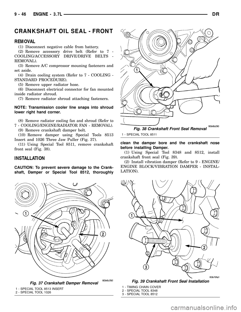
(10) Remove damper using Special Tools 8513
Insert and 1026 Three Jaw Puller (Fig. 37).
(11) Using Special Tool 8511, remove crankshaft
front seal (Fig. 38).
INSTALLATION
CAUTION: To prevent severe damage to the Crank-
shaft, Damper or Special Tool 8512, thoroughlyclean the damper bore and the crankshaft nose
before installing Damper.
(1) Using Special Tool 8348 and 8512, install
crankshaft front seal (Fig. 39).
(2) Install vibration damper (Refer to 9 - ENGINE/
ENGINE BLOCK/VIBRATION DAMPER - INSTAL-
LATION).
Fig. 37 Crankshaft Damper Removal
1 - SPECIAL TOOL 8513 INSERT
2 - SPECIAL TOOL 1026
Fig. 39 Crankshaft Front Seal Installation
1 - TIMING CHAIN COVER
2 - SPECIAL TOOL 8348
3 - SPECIAL TOOL 8512
Fig. 38 Crankshaft Front Seal Removal
1 - SPECIAL TOOL 8511
9 - 46 ENGINE - 3.7LDR
Page 1270 of 2627
(3) Install radiator cooling fan and shroud (Refer
to 7 - COOLING/ENGINE/RADIATOR FAN -
INSTALLATION).
(4) Install upper radiator hose.
(5) Install A/C compressor and tighten fasteners to
54 N´m (40 ft. lbs.).
(6) Install accessory drive belt refer (Refer to 7 -
COOLING/ACCESSORY DRIVE/DRIVE BELTS -
INSTALLATION).
(7) Refill cooling system (Refer to 7 - COOLING -
STANDARD PROCEDURE).
(8) Connect negative cable to battery.
CRANKSHAFT OIL SEAL -
REAR
REMOVAL
NOTE: This procedure can be performed in vehicle.
(1) If being preformed in vehicle, remove the
transmission.
(2) Remove the flexplate (Refer to 9 - ENGINE/
ENGINE BLOCK/FLEX PLATE - REMOVAL).
NOTE: The crankshaft oil seal CAN NOT be reused
after removal.
NOTE: The crankshaft rear oil seal remover Special
Tool 8506 must be installed deeply into the seal.
Continue to tighten the removal tool into the seal
until the tool can not be turned farther. Failure to
install tool correctly the first time will cause tool to
pull free of seal without removing seal from engine.
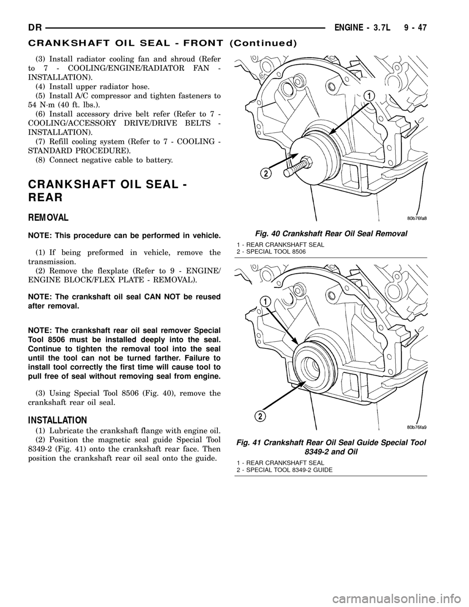
(3) Using Special Tool 8506 (Fig. 40), remove the
crankshaft rear oil seal.
INSTALLATION
(1) Lubricate the crankshaft flange with engine oil.
(2) Position the magnetic seal guide Special Tool
8349-2 (Fig. 41) onto the crankshaft rear face. Then
position the crankshaft rear oil seal onto the guide.
Fig. 40 Crankshaft Rear Oil Seal Removal
1 - REAR CRANKSHAFT SEAL
2 - SPECIAL TOOL 8506
Fig. 41 Crankshaft Rear Oil Seal Guide Special Tool
8349-2 and Oil
1 - REAR CRANKSHAFT SEAL
2 - SPECIAL TOOL 8349-2 GUIDE
DRENGINE - 3.7L 9 - 47
CRANKSHAFT OIL SEAL - FRONT (Continued)
Page 1274 of 2627
(10) Once you have selected the proper insert,
install the insert and cap. Tighten the connecting rod
bolts to 27 N´m (20 ft. lbs.) plus a 90É turn.
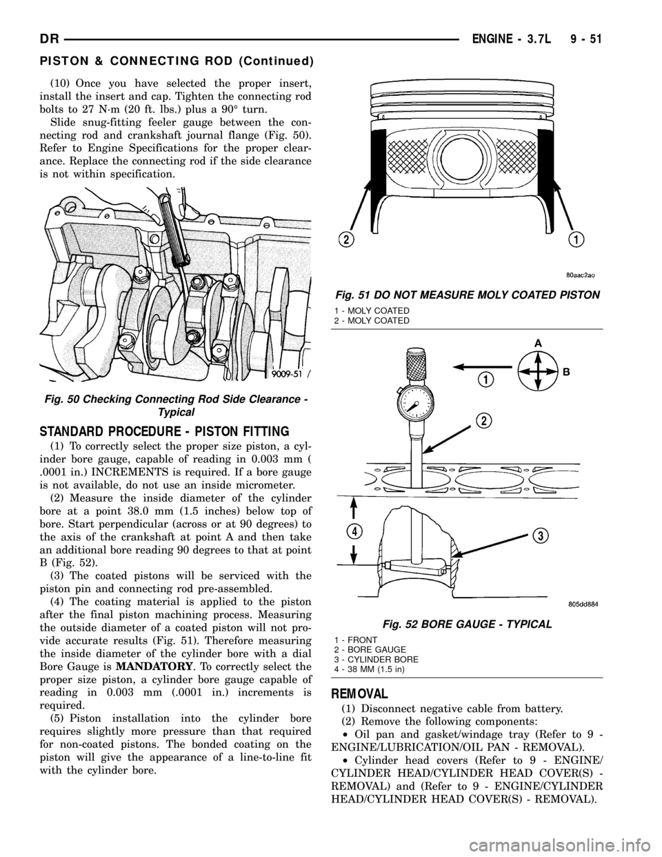
Slide snug-fitting feeler gauge between the con-
necting rod and crankshaft journal flange (Fig. 50).
Refer to Engine Specifications for the proper clear-
ance. Replace the connecting rod if the side clearance
is not within specification.
STANDARD PROCEDURE - PISTON FITTING
(1) To correctly select the proper size piston, a cyl-
inder bore gauge, capable of reading in 0.003 mm (
.0001 in.) INCREMENTS is required. If a bore gauge
is not available, do not use an inside micrometer.
(2) Measure the inside diameter of the cylinder
bore at a point 38.0 mm (1.5 inches) below top of
bore. Start perpendicular (across or at 90 degrees) to
the axis of the crankshaft at point A and then take
an additional bore reading 90 degrees to that at point
B (Fig. 52).
(3) The coated pistons will be serviced with the
piston pin and connecting rod pre-assembled.
(4) The coating material is applied to the piston
after the final piston machining process. Measuring
the outside diameter of a coated piston will not pro-
vide accurate results (Fig. 51). Therefore measuring
the inside diameter of the cylinder bore with a dial
Bore Gauge isMANDATORY. To correctly select the
proper size piston, a cylinder bore gauge capable of
reading in 0.003 mm (.0001 in.) increments is
required.
(5) Piston installation into the cylinder bore
requires slightly more pressure than that required
for non-coated pistons. The bonded coating on the
piston will give the appearance of a line-to-line fit
with the cylinder bore.
REMOVAL
(1) Disconnect negative cable from battery.
(2) Remove the following components:
²Oil pan and gasket/windage tray (Refer to 9 -
ENGINE/LUBRICATION/OIL PAN - REMOVAL).
²Cylinder head covers (Refer to 9 - ENGINE/
CYLINDER HEAD/CYLINDER HEAD COVER(S) -
REMOVAL) and (Refer to 9 - ENGINE/CYLINDER
HEAD/CYLINDER HEAD COVER(S) - REMOVAL).
Fig. 50 Checking Connecting Rod Side Clearance -
Typical
Fig. 51 DO NOT MEASURE MOLY COATED PISTON
1 - MOLY COATED
2 - MOLY COATED
Fig. 52 BORE GAUGE - TYPICAL
1 - FRONT
2 - BORE GAUGE
3 - CYLINDER BORE
4 - 38 MM (1.5 in)
DRENGINE - 3.7L 9 - 51
PISTON & CONNECTING ROD (Continued)
Page 1276 of 2627
²Timing chain and cover. (Refer to 9 - ENGINE/
VALVE TIMING/TIMING BELT / CHAIN COVER(S)
- INSTALLATION).
²Cylinder head covers (Refer to 9 - ENGINE/
CYLINDER HEAD/CYLINDER HEAD COVER(S) -
INSTALLATION).
²Oil pan and gasket/windage tray. (Refer to 9 -
ENGINE/LUBRICATION/OIL PAN - INSTALLA-
TION).
(11) Fill crankcase with proper engine oil to cor-
rect level.
(12) Connect negative cable to battery.
PISTON RINGS
STANDARD PROCEDURE - PISTON RING
FITTING
Before reinstalling used rings or installing new
rings, the ring clearances must be checked.
(1) Wipe the cylinder bore clean.
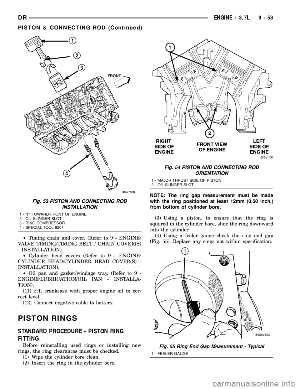
(2) Insert the ring in the cylinder bore.NOTE: The ring gap measurement must be made
with the ring positioned at least 12mm (0.50 inch.)
from bottom of cylinder bore.
(3) Using a piston, to ensure that the ring is
squared in the cylinder bore, slide the ring downward
into the cylinder.
(4) Using a feeler gauge check the ring end gap
(Fig. 55). Replace any rings not within specification.
Fig. 53 PISTON AND CONNECTING ROD
INSTALLATION
1 - ªFº TOWARD FRONT OF ENGINE
2 - OIL SLINGER SLOT
3 - RING COMPRESSOR
4 - SPECIAL TOOL 8507
Fig. 54 PISTON AND CONNECTING ROD
ORIENTATION
1 - MAJOR THRUST SIDE OF PISTON
2 - OIL SLINGER SLOT
Fig. 55 Ring End Gap Measurement - Typical
1 - FEELER GAUGE
DRENGINE - 3.7L 9 - 53
PISTON & CONNECTING ROD (Continued)
Page 1278 of 2627
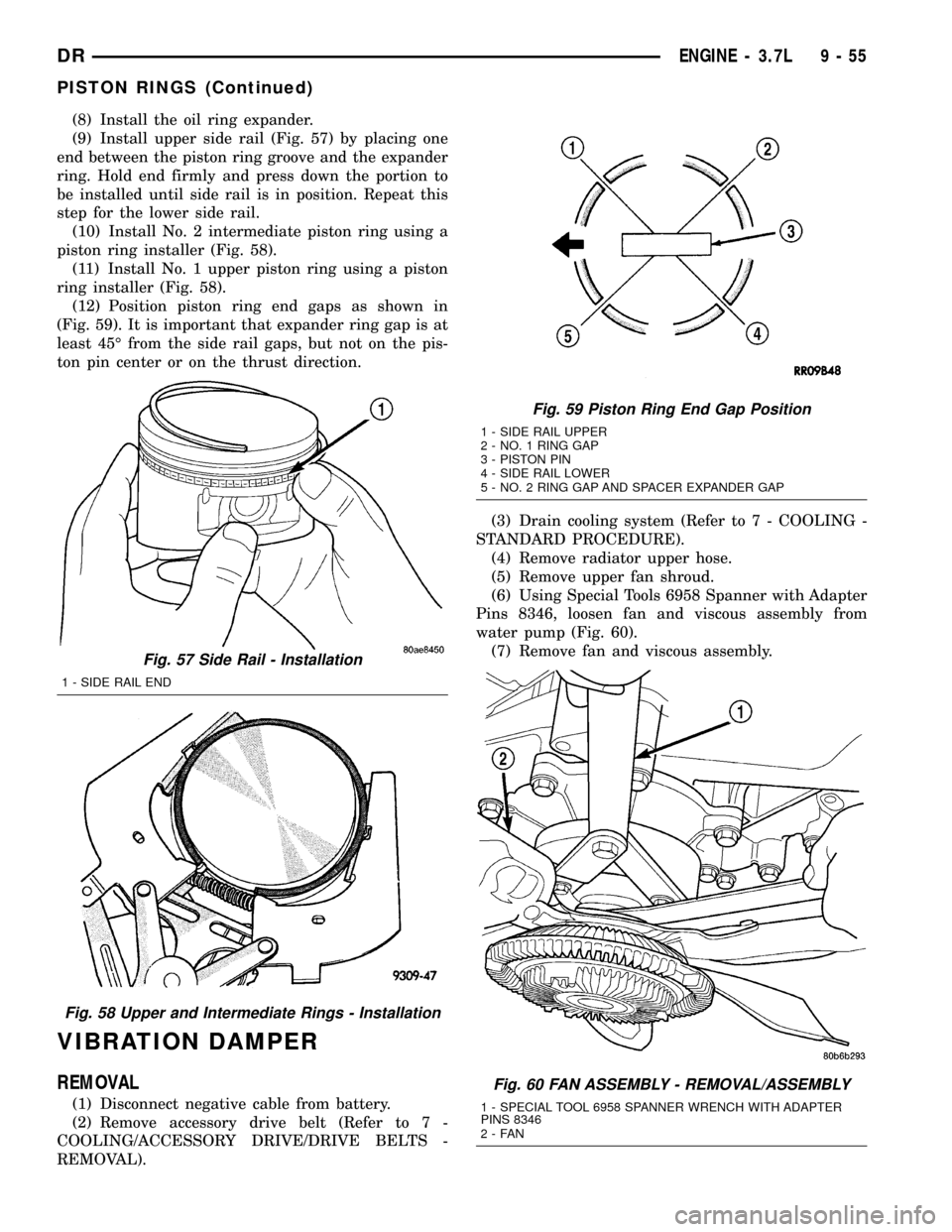
(8) Install the oil ring expander.
(9) Install upper side rail (Fig. 57) by placing one
end between the piston ring groove and the expander
ring. Hold end firmly and press down the portion to
be installed until side rail is in position. Repeat this
step for the lower side rail.
(10) Install No. 2 intermediate piston ring using a
piston ring installer (Fig. 58).
(11) Install No. 1 upper piston ring using a piston
ring installer (Fig. 58).
(12) Position piston ring end gaps as shown in
(Fig. 59). It is important that expander ring gap is at
least 45É from the side rail gaps, but not on the pis-
ton pin center or on the thrust direction.
VIBRATION DAMPER
REMOVAL
(1) Disconnect negative cable from battery.
(2) Remove accessory drive belt (Refer to 7 -
COOLING/ACCESSORY DRIVE/DRIVE BELTS -
REMOVAL).(3) Drain cooling system (Refer to 7 - COOLING -
STANDARD PROCEDURE).
(4) Remove radiator upper hose.
(5) Remove upper fan shroud.
(6) Using Special Tools 6958 Spanner with Adapter
Pins 8346, loosen fan and viscous assembly from
water pump (Fig. 60).
(7) Remove fan and viscous assembly.
Fig. 57 Side Rail - Installation
1 - SIDE RAIL END
Fig. 58 Upper and Intermediate Rings - Installation
Fig. 59 Piston Ring End Gap Position
1 - SIDE RAIL UPPER
2 - NO. 1 RING GAP
3 - PISTON PIN
4 - SIDE RAIL LOWER
5 - NO. 2 RING GAP AND SPACER EXPANDER GAP
Fig. 60 FAN ASSEMBLY - REMOVAL/ASSEMBLY
1 - SPECIAL TOOL 6958 SPANNER WRENCH WITH ADAPTER
PINS 8346
2-FAN
DRENGINE - 3.7L 9 - 55
PISTON RINGS (Continued)
Page 1280 of 2627
(5) Install fan blade assembly (Refer to 7 - COOL-
ING/ENGINE/FAN DRIVE VISCOUS CLUTCH -
INSTALLATION).
(6) Install radiator upper shroud and tighten fas-
teners to 11 N´m (95 in. lbs.).
(7) Connect electrical connector for shroud fan.
(8) Install radiator upper hose.
(9) Install accessory drive belt (Refer to 7 - COOL-
ING/ACCESSORY DRIVE/DRIVE BELTS - INSTAL-
LATION).
(10) Refill cooling system (Refer to 7 - COOLING -
STANDARD PROCEDURE).
(11) Connect negative cable to battery.
STRUCTURAL COVER
DESCRIPTION
The structural dust cover is made of die cast alu-
minum and joins the lower half of the transmission
bell housing to the engine bedplate.
OPERATION
The structural cover provides additional power-
train stiffness and reduces noise and vibration.
REMOVAL
(1) Raise vehicle on hoist.
(2) Remove the left hand exhaust pipe from
exhaust manifold.
(3) Loosen the right hand exhaust manifold-to-ex-
haust pipe retaining bolts.
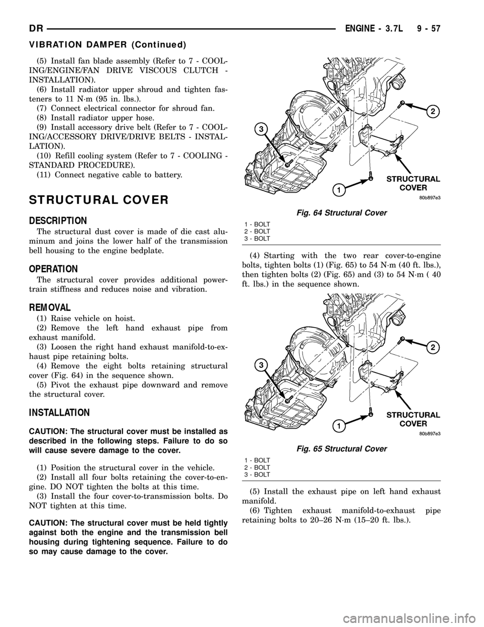
(4) Remove the eight bolts retaining structural
cover (Fig. 64) in the sequence shown.
(5) Pivot the exhaust pipe downward and remove
the structural cover.
INSTALLATION
CAUTION: The structural cover must be installed as
described in the following steps. Failure to do so
will cause severe damage to the cover.
(1) Position the structural cover in the vehicle.
(2) Install all four bolts retaining the cover-to-en-
gine. DO NOT tighten the bolts at this time.
(3) Install the four cover-to-transmission bolts. Do
NOT tighten at this time.
CAUTION: The structural cover must be held tightly
against both the engine and the transmission bell
housing during tightening sequence. Failure to do
so may cause damage to the cover.(4) Starting with the two rear cover-to-engine
bolts, tighten bolts (1) (Fig. 65) to 54 N´m (40 ft. lbs.),
then tighten bolts (2) (Fig. 65) and (3) to 54 N´m ( 40
ft. lbs.) in the sequence shown.
(5) Install the exhaust pipe on left hand exhaust
manifold.
(6) Tighten exhaust manifold-to-exhaust pipe
retaining bolts to 20±26 N´m (15±20 ft. lbs.).
Fig. 64 Structural Cover
1 - BOLT
2 - BOLT
3 - BOLT
Fig. 65 Structural Cover
1 - BOLT
2 - BOLT
3 - BOLT
DRENGINE - 3.7L 9 - 57
VIBRATION DAMPER (Continued)
Page 1281 of 2627
FRONT MOUNT
REMOVAL
2WD
(1) Disconnect the negative cable from the battery.
CAUTION: Remove the viscous fan before raising
engine. Failure to do so may cause damage to the
fan blade, fan clutch and fan shroud.
(2) Remove the viscous fan (Refer to 7 - COOL-
ING/ENGINE/FAN DRIVE VISCOUS CLUTCH -
REMOVAL).
(3) Raise the vehicle.
(4) Remove the engine oil filter.
(5) Remove the oil drain trough.
(6)
Support the engine with a suitable jack and a
block of wood across the full width of the engine oil pan.
(7) Support the front axle with a suitable jack.
(8) Remove the (4) bolts that attach the engine
mounts to the front axle.
(9) Remove the (3) bolts that attach the front axle
to the left engine bracket.
(10) Lower the front axle.
(11) Remove the through bolts(12) Raise the engine far enough to be able to
remove the left and right engine mounts.
(13) Remove the (8) mount to engine attaching
bolts
(14) Remove the engine mounts.
4WD
(1) Disconnect the negative cable from the battery.
CAUTION: Remove the viscous fan before raising
engine. Failure to do so may cause damage to the
fan blade, fan clutch and fan shroud.
(2) Remove the viscous fan (Refer to 7 - COOL-
ING/ENGINE/FAN DRIVE VISCOUS CLUTCH -
REMOVAL).
(3) Raise the vehicle.
(4) Remove the skid plate.
(5) Remove the front crossmember.
(6) Remove the engine oil filter.
(7) Remove the oil drain trough.
(8) Support the engine with a suitable jack and a
block of wood across the full width of the engine oil
pan.
(9) Support the front axle with a suitable jack.
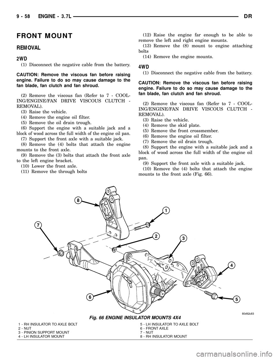
(10) Remove the (4) bolts that attach the engine
mounts to the front axle (Fig. 66).
Fig. 66 ENGINE INSULATOR MOUNTS 4X4
1 - RH INSULATOR TO AXLE BOLT
2 - NUT
3 - PINION SUPPORT MOUNT
4 - LH INSULATOR MOUNT5 - LH INSULATOR TO AXLE BOLT
6 - FRONT AXLE
7 - NUT
8 - RH INSULATOR MOUNT
9 - 58 ENGINE - 3.7LDR
Page 1282 of 2627
(11) Remove the (3) bolts that attach the front axle
to the left engine bracket.
(12) Lower the front axle.
(13) Remove the (6) through bolts
(14) Raise the engine far enough to be able to
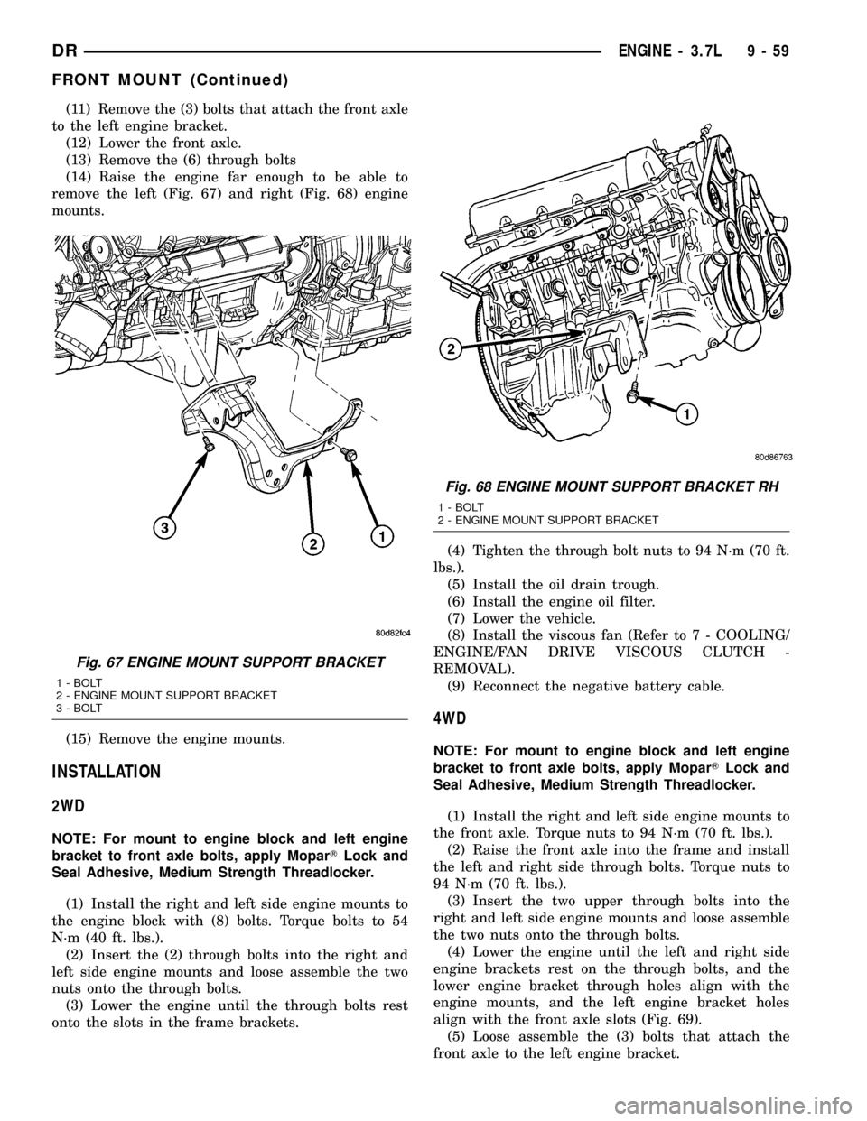
remove the left (Fig. 67) and right (Fig. 68) engine
mounts.
(15) Remove the engine mounts.
INSTALLATION
2WD
NOTE: For mount to engine block and left engine
bracket to front axle bolts, apply MoparTLock and
Seal Adhesive, Medium Strength Threadlocker.
(1) Install the right and left side engine mounts to
the engine block with (8) bolts. Torque bolts to 54
N´m (40 ft. lbs.).
(2) Insert the (2) through bolts into the right and
left side engine mounts and loose assemble the two
nuts onto the through bolts.
(3) Lower the engine until the through bolts rest
onto the slots in the frame brackets.(4) Tighten the through bolt nuts to 94 N´m (70 ft.
lbs.).
(5) Install the oil drain trough.
(6) Install the engine oil filter.
(7) Lower the vehicle.
(8) Install the viscous fan (Refer to 7 - COOLING/
ENGINE/FAN DRIVE VISCOUS CLUTCH -
REMOVAL).
(9) Reconnect the negative battery cable.
4WD
NOTE: For mount to engine block and left engine
bracket to front axle bolts, apply MoparTLock and
Seal Adhesive, Medium Strength Threadlocker.
(1) Install the right and left side engine mounts to
the front axle. Torque nuts to 94 N´m (70 ft. lbs.).
(2) Raise the front axle into the frame and install
the left and right side through bolts. Torque nuts to
94 N´m (70 ft. lbs.).
(3) Insert the two upper through bolts into the
right and left side engine mounts and loose assemble
the two nuts onto the through bolts.
(4) Lower the engine until the left and right side
engine brackets rest on the through bolts, and the
lower engine bracket through holes align with the
engine mounts, and the left engine bracket holes
align with the front axle slots (Fig. 69).
(5) Loose assemble the (3) bolts that attach the
front axle to the left engine bracket.
Fig. 67 ENGINE MOUNT SUPPORT BRACKET
1 - BOLT
2 - ENGINE MOUNT SUPPORT BRACKET
3 - BOLT
Fig. 68 ENGINE MOUNT SUPPORT BRACKET RH
1 - BOLT
2 - ENGINE MOUNT SUPPORT BRACKET
DRENGINE - 3.7L 9 - 59
FRONT MOUNT (Continued)