1998 DODGE RAM 1500 battery
[x] Cancel search: batteryPage 1061 of 2627
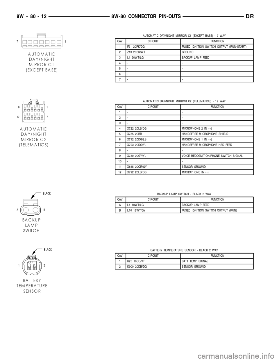
AUTOMATIC DAY/NIGHT MIRROR C1 (EXCEPT BASE)-7WAY
CAV CIRCUIT FUNCTION
1 F21 20PK/DG FUSED IGNITION SWITCH OUTPUT (RUN-START)
2 Z13 20BK/WT GROUND
3 L1 20WT/LG BACKUP LAMP FEED
4- -
5- -
6- -
7- -
AUTOMATIC DAY/NIGHT MIRROR C2 (TELEMATICS) - 12 WAY
CAV CIRCUIT FUNCTION
1- -
2- -
3- -
4 X722 20LB/DG MICROPHONE 2 IN (+)
5 X735 20BR HANDSFREE MICROPHONE SHIELD
6 X712 20DG/LB MICROPHONE 1 IN (+)
7 X793 20DG/YL HANDSFREE MICROPHONE HSD FEED
8- -
9 X730 20GY/YL VOICE RECOGNITION/PHONE SWITCH SIGNAL
10 - -
11 X835 20OR/GY SENSOR GROUND
12 X792 20LB/DG MICROPHONE IN (-)
BACKUP LAMP SWITCH - BLACK 2 WAY
CAV CIRCUIT FUNCTION
A L1 18WT/LG BACKUP LAMP FEED
B L10 18WT/GY FUSED IGNITION SWITCH OUTPUT (RUN)
BATTERY TEMPERATURE SENSOR - BLACK 2 WAY
CAV CIRCUIT FUNCTION
1 K25 18DB/VT BATT TEMP SIGNAL
2 K900 20DB/DG SENSOR GROUND
8W - 80 - 12 8W-80 CONNECTOR PIN-OUTSDR
Page 1154 of 2627
8W-91 CONNECTOR/GROUND/SPLICE LOCATION
TABLE OF CONTENTS
page
CONNECTOR/GROUND/SPLICE LOCATION
DESCRIPTION..........................1
CONNECTOR/GROUND/SPLICE
LOCATION
DESCRIPTION
This section provides illustrations identifying con-
nector, ground, and splice locations in the vehicle.
Connector, ground, and splice indexes are provided.Use the wiring diagrams in each section for connec-
tor, ground, and splice identification. Refer to the
index for the proper figure number. For items that
are not shown in this section N/S is placed in the
Fig. column.
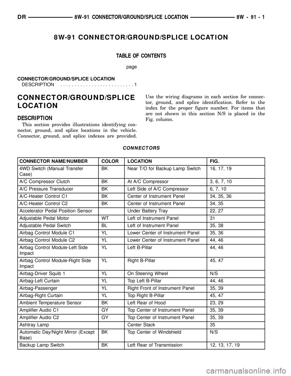
CONNECTORS
CONNECTOR NAME/NUMBER COLOR LOCATION FIG.
4WD Switch (Manual Transfer
Case)BK Near T/O for Backup Lamp Switch 16, 17, 19
A/C Compressor Clutch BK At A/C Compressor 3, 6, 7, 10
A/C Pressure Transducer BK Left Side of A/C Compressor 6, 7, 10
A/C-Heater Control C1 BK Center of Instrument Panel 34, 35, 36
A/C-Heater Control C2 BK Center of Instrument Panel 34, 35
Accelerator Pedal Position Sensor Under Battery Tray 22, 27
Adjustable Pedal Motor WT Left of Instrument Panel 31
Adjustable Pedal Switch BL Left of Instrument Panel 35, 38
Airbag Control Module C1 YL Lower Center of Instrument Panel 35, 36
Airbag Control Module C2 YL Lower Center of Instrument Panel 44, 46
Airbag Control Module-Left Side
ImpactYL Left B-Pillar 44, 46
Airbag Control Module-Right Side
ImpactYL Right B-Pillar 45, 47
Airbag-Driver Squib 1 YL On Steering Wheel N/S
Airbag-Left Curtain YL Top Left B-Pillar 44, 46
Airbag-Passenger YL Right Front of Instrument Panel 35, 39
Airbag-Right Curtain YL Top Right B-Pillar 45, 47
Ambient Temperature Sensor BK Left Rear of Hood 23, 29
Amplifier Audio C1 GY Top Center of Instrument Panel 35, 39
Amplifier Audio C2 GY Top Center of Instrument Panel 35, 39
Ashtray Lamp Center Stack 35
Automatic Day/Night Mirror (Except
Base)BK Top Center of Windshield N/S
Backup Lamp Switch BK Left Rear of Transmission 12, 13, 17, 19
DR8W-91 CONNECTOR/GROUND/SPLICE LOCATION 8W - 91 - 1
Page 1155 of 2627
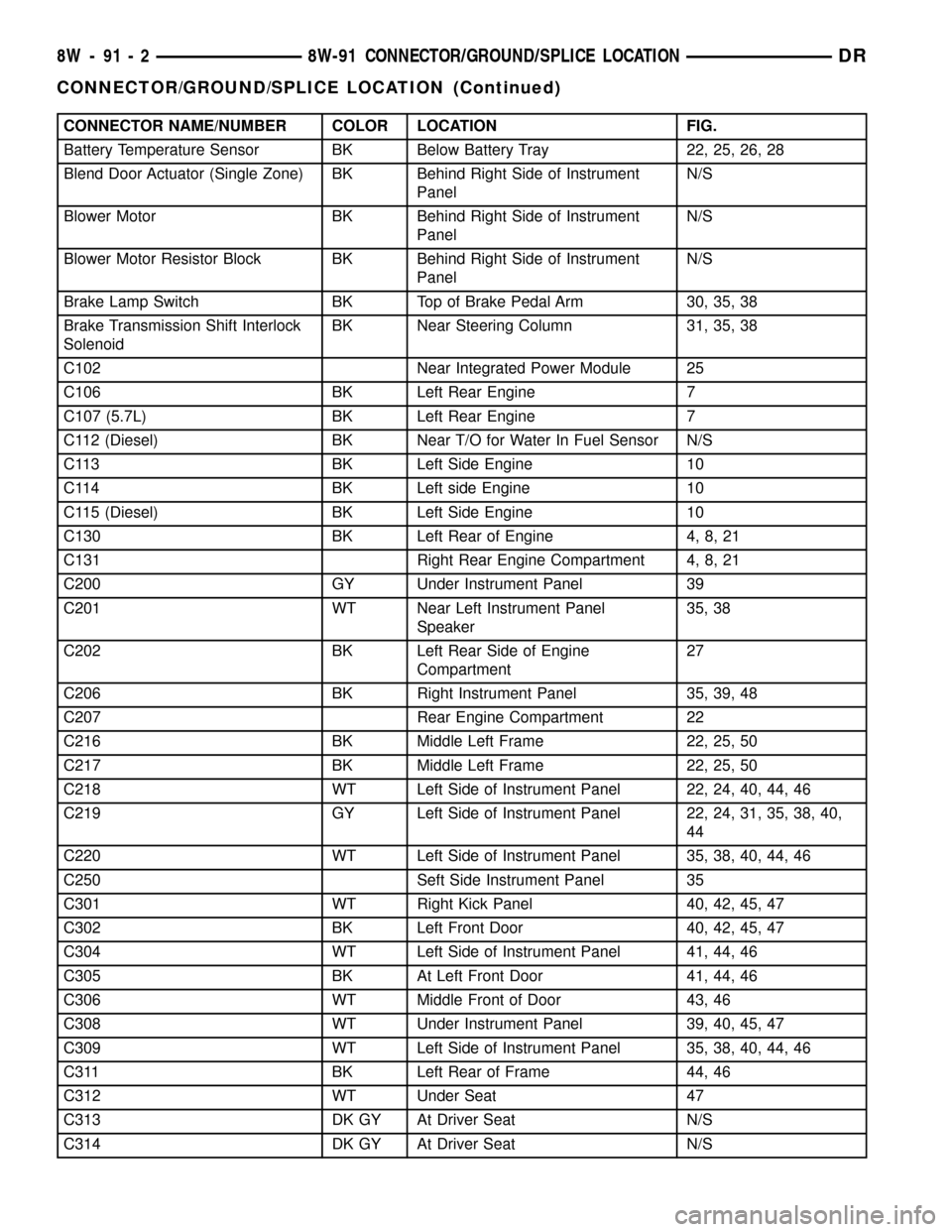
CONNECTOR NAME/NUMBER COLOR LOCATION FIG.
Battery Temperature Sensor BK Below Battery Tray 22, 25, 26, 28
Blend Door Actuator (Single Zone) BK Behind Right Side of Instrument
PanelN/S
Blower Motor BK Behind Right Side of Instrument
PanelN/S
Blower Motor Resistor Block BK Behind Right Side of Instrument
PanelN/S
Brake Lamp Switch BK Top of Brake Pedal Arm 30, 35, 38
Brake Transmission Shift Interlock
SolenoidBK Near Steering Column 31, 35, 38
C102 Near Integrated Power Module 25
C106 BK Left Rear Engine 7
C107 (5.7L) BK Left Rear Engine 7
C112 (Diesel) BK Near T/O for Water In Fuel Sensor N/S
C113 BK Left Side Engine 10
C114 BK Left side Engine 10
C115 (Diesel) BK Left Side Engine 10
C130 BK Left Rear of Engine 4, 8, 21
C131 Right Rear Engine Compartment 4, 8, 21
C200 GY Under Instrument Panel 39
C201 WT Near Left Instrument Panel
Speaker35, 38
C202 BK Left Rear Side of Engine
Compartment27
C206 BK Right Instrument Panel 35, 39, 48
C207 Rear Engine Compartment 22
C216 BK Middle Left Frame 22, 25, 50
C217 BK Middle Left Frame 22, 25, 50
C218 WT Left Side of Instrument Panel 22, 24, 40, 44, 46
C219 GY Left Side of Instrument Panel 22, 24, 31, 35, 38, 40,
44
C220 WT Left Side of Instrument Panel 35, 38, 40, 44, 46
C250 Seft Side Instrument Panel 35
C301 WT Right Kick Panel 40, 42, 45, 47
C302 BK Left Front Door 40, 42, 45, 47
C304 WT Left Side of Instrument Panel 41, 44, 46
C305 BK At Left Front Door 41, 44, 46
C306 WT Middle Front of Door 43, 46
C308 WT Under Instrument Panel 39, 40, 45, 47
C309 WT Left Side of Instrument Panel 35, 38, 40, 44, 46
C311 BK Left Rear of Frame 44, 46
C312 WT Under Seat 47
C313 DK GY At Driver Seat N/S
C314 DK GY At Driver Seat N/S
8W - 91 - 2 8W-91 CONNECTOR/GROUND/SPLICE LOCATIONDR
CONNECTOR/GROUND/SPLICE LOCATION (Continued)
Page 1162 of 2627
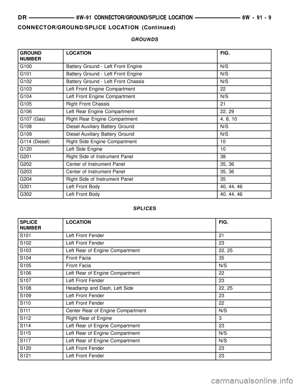
GROUNDS
GROUND
NUMBERLOCATION FIG.
G100 Battery Ground - Left Front Engine N/S
G101 Battery Ground - Left Front Engine N/S
G102 Battery Ground - Left Front Chassis N/S
G103 Left Front Engine Compartment 22
G104 Left Front Engine Compartment N/S
G105 Right Front Chassis 21
G106 Left Rear Engine Compartment 22, 29
G107 (Gas) Right Rear Engine Compartment 4, 8, 10
G108 Diesel Auxiliary Battery Ground N/S
G109 Diesel Auxiliary Battery Ground N/S
G114 (Diesel) Right Side Engine Compartment 10
G120 Left Side Engine 10
G201 Right Side of Instrument Panel 38
G202 Center of Instrument Panel 35, 36
G203 Center of Instrument Panel 35, 36
G204 Right Side of Instrument Panel 35
G301 Left Front Body 40, 44, 46
G302 Left Front Body 40, 44, 46
SPLICES
SPLICE
NUMBERLOCATION FIG.
S101 Left Front Fender 21
S102 Left Front Fender 23
S103 Left Rear of Engine Compartment 22, 25
S104 Front Facia 35
S105 Front Facia N/S
S106 Left Rear of Engine Compartment 22
S107 Left Front Fender 23
S108 Headlamp and Dash, Left Side 22, 25
S109 Left Front Fender 23
S110 Left Front Fender 22
S111 Center Rear of Engine Compartment N/S
S112 Right Rear of Engine 3
S114 Left Rear of Engine Compartment 23
S115 Left Rear of Engine Compartment N/S
S117 Left Rear of Engine Compartment N/S
S120 Left Front Fender 23
S121 Left Front Fender 23
DR8W-91 CONNECTOR/GROUND/SPLICE LOCATION 8W - 91 - 9
CONNECTOR/GROUND/SPLICE LOCATION (Continued)
Page 1163 of 2627
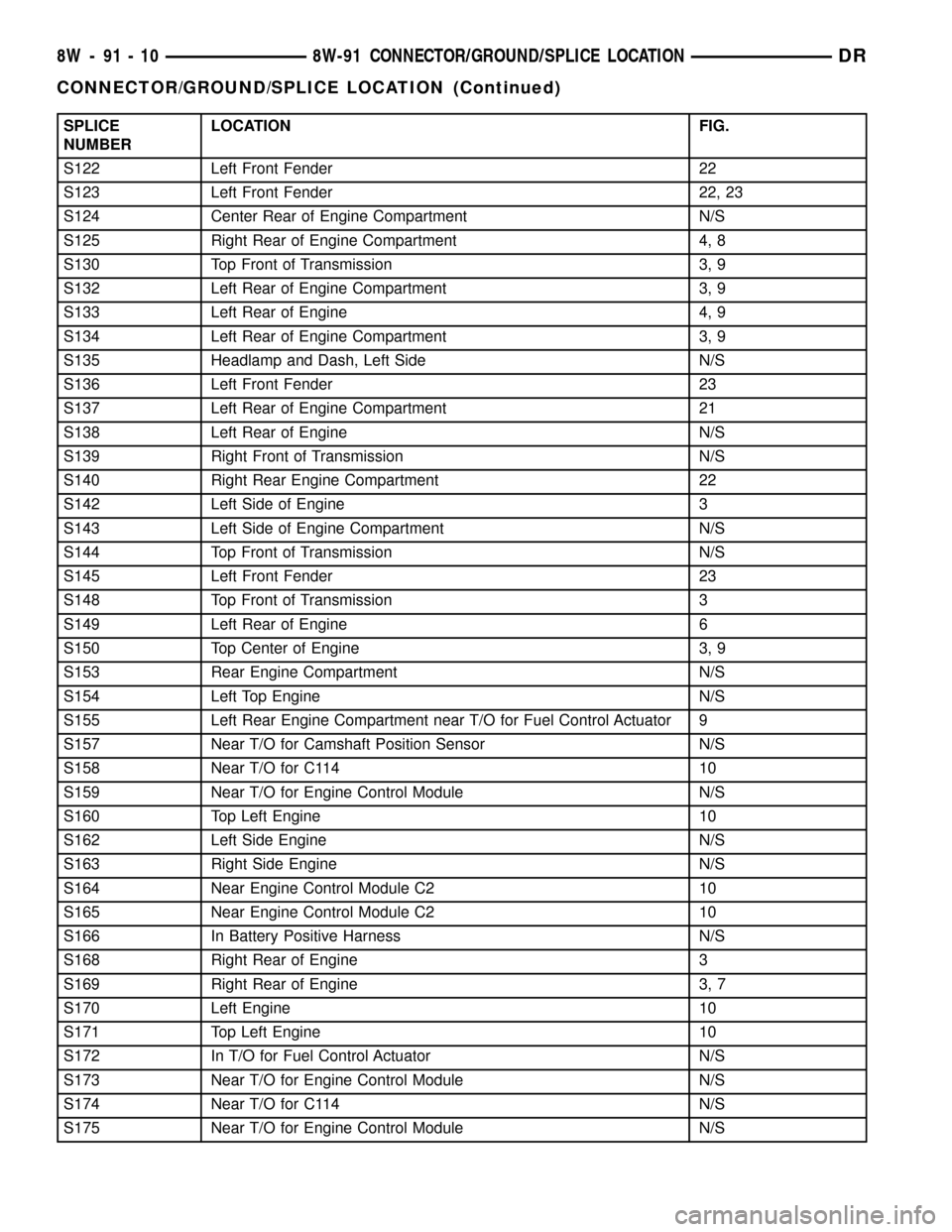
SPLICE
NUMBERLOCATION FIG.
S122 Left Front Fender 22
S123 Left Front Fender 22, 23
S124 Center Rear of Engine Compartment N/S
S125 Right Rear of Engine Compartment 4, 8
S130 Top Front of Transmission 3, 9
S132 Left Rear of Engine Compartment 3, 9
S133 Left Rear of Engine 4, 9
S134 Left Rear of Engine Compartment 3, 9
S135 Headlamp and Dash, Left Side N/S
S136 Left Front Fender 23
S137 Left Rear of Engine Compartment 21
S138 Left Rear of Engine N/S
S139 Right Front of Transmission N/S
S140 Right Rear Engine Compartment 22
S142 Left Side of Engine 3
S143 Left Side of Engine Compartment N/S
S144 Top Front of Transmission N/S
S145 Left Front Fender 23
S148 Top Front of Transmission 3
S149 Left Rear of Engine 6
S150 Top Center of Engine 3, 9
S153 Rear Engine Compartment N/S
S154 Left Top Engine N/S
S155 Left Rear Engine Compartment near T/O for Fuel Control Actuator 9
S157 Near T/O for Camshaft Position Sensor N/S
S158 Near T/O for C114 10
S159 Near T/O for Engine Control Module N/S
S160 Top Left Engine 10
S162 Left Side Engine N/S
S163 Right Side Engine N/S
S164 Near Engine Control Module C2 10
S165 Near Engine Control Module C2 10
S166 In Battery Positive Harness N/S
S168 Right Rear of Engine 3
S169 Right Rear of Engine 3, 7
S170 Left Engine 10
S171 Top Left Engine 10
S172 In T/O for Fuel Control Actuator N/S
S173 Near T/O for Engine Control Module N/S
S174 Near T/O for C114 N/S
S175 Near T/O for Engine Control Module N/S
8W - 91 - 10 8W-91 CONNECTOR/GROUND/SPLICE LOCATIONDR
CONNECTOR/GROUND/SPLICE LOCATION (Continued)
Page 1166 of 2627

Fig. 1 RIGHT SIDE FRONT LIGHTING
Fig. 2 LEFT FRONT BUMPER AND RIGHT BATTERY TRAY
DR8W-91 CONNECTOR/GROUND/SPLICE LOCATION 8W - 91 - 13
CONNECTOR/GROUND/SPLICE LOCATION (Continued)
Page 1190 of 2627

Fig. 27 27 LEFT FRONT FACIA AND BATTERY TRAY
DR8W-91 CONNECTOR/GROUND/SPLICE LOCATION 8W - 91 - 37
CONNECTOR/GROUND/SPLICE LOCATION (Continued)
Page 1217 of 2627

SPECIAL TOOLS
POWER DISTRIBUTION SYSTEMS
CIGAR LIGHTER OUTLET
DESCRIPTION
On models equipped a cigar lighter outlet is
installed to the left of the center stack area in the
lower instrument panel. The cigar lighter outlet is
secured by a snap fit within the bezel.
The cigar lighter outlet, plastic cap and the knob
and heating element unit are available for service
replacement. These components cannot be repaired
and, if faulty or damaged, they must be replaced.
OPERATION
The cigar lighter consists of two major components:
a knob and heating element unit, and the cigar
lighter base or outlet shell. The receptacle shell is
connected to ground, and an insulated contact in the
bottom of the shell is connected to battery current.
The cigar lighter receives battery voltage from a fuse
in the junction block when the ignition switch is in
the Accessory or Run positions.
The cigar lighter knob and heating element are
encased within a spring-loaded housing, which also
features a sliding protective heat shield. When the
knob and heating element are inserted in the outlet
shell, the heating element resistor coil is grounded
through its housing to the outlet shell. If the cigar
lighter knob is pushed inward, the heat shield slides
up toward the knob exposing the heating element,
and the heating element extends from the housing
toward the insulated contact in the bottom of the
outlet shell.
Two small spring-clip retainers are located on
either side of the insulated contact inside the bottom
of the outlet shell. These clips engage and hold the
heating element against the insulated contact longenough for the resistor coil to heat up. When the
heating element is engaged with the contact, battery
current can flow through the resistor coil to ground,
causing the resistor coil to heat.
When the resistor coil becomes sufficiently heated,
excess heat radiates from the heating element caus-
ing the spring-clips to expand. Once the spring-clips
expand far enough to release the heating element,
the spring-loaded housing forces the knob and heat-
ing element to pop back outward to their relaxed
position. When the cigar lighter knob and element
are pulled out of the outlet shell, the protective heat
shield slides downward on the housing so that the
heating element is recessed and shielded around its
circumference for safety.
DIAGNOSIS AND TESTING - CIGAR LIGHTER
OUTLET
For complete circuit diagrams, refer toWiring
Diagrams.
(1) Check the fused B(+) fuse in the integrated
power module. If OK, go to Step 2. If not OK, repair
the shorted circuit or component as required and
replace the faulty fuse.
(2) Turn the ignition switch to the Run position.
Check for battery voltage at the fused B(+) fuse in
the integrated power module. If OK, go to Step 3. If
not OK, repair the open or short as required.
(3) Remove the cigar lighter knob and element
from the cigar lighter outlet shell. Check for continu-
ity between the inside circumference of the cigar
lighter outlet shell and a good ground. there should
be continuity. If OK, go to Step 4. If not OK, go to
Step 5.
(4) Turn the ignition switch to the Run position.
Check for battery voltage at the insulated contact
located at the back of the cigar lighter outlet shell. If
OK, replace the faulty cigar lighter knob and ele-
ment. If not OK, go to Step 5.
(5) Turn the ignition switch to the Off position.
Disconnect and isolate the battery negative cable.
Check for continuity between the ground circuit cav-
ity of the cigar lighter wire harness connector and a
good ground. There should be continuity. If OK, go to
Step 6. If not OK, repair the open ground circuit to
ground as required.
(6) Connect the battery negative cable. Turn the
ignition switch to the Accessory or Run positions.
Check for battery voltage at the fused B(+) circuit
cavity of the cigar lighter wire harness connector. If
OK, replace the faulty cigar lighter outlet. If not OK,
repair the open fused B(+) circuit to the integrated
power module fuse as required.Terminal Pick Kit 6680
8W - 97 - 2 8W-97 POWER DISTRIBUTIONDR
POWER DISTRIBUTION (Continued)