1998 DODGE RAM 1500 Washer
[x] Cancel search: WasherPage 2227 of 2627
REAR EXTENSION HOUSING
Inspect the extension housing seal and bushing.
Replace both components if either show any sign of
wear or damage.
FRONT OUTPUT SHAFT AND DRIVE CHAIN
Inspect the shaft splines and bearing surfaces.
Minor nicks on the splines can be smoothed with an
oilstone. Use 320-400 grit emery to smooth minor
scratches on the shaft bearing surfaces. Replace the
shaft if the bearing surfaces are scored or if any of
the splines are cracked or broken.Examine the drive chain and shaft bearings.
Replace the chain and both sprockets if the chain is
stretched, distorted, or if any of the links bind.
Replace the bearings if rough, or noisy.
LOW RANGE ANNULUS GEAR
Inspect annulus gear condition carefully. The gear
is only serviced as part of the front case. If the gear
is damaged, it will be necessary to replace the gear
and front case as an assembly. Do not attempt to
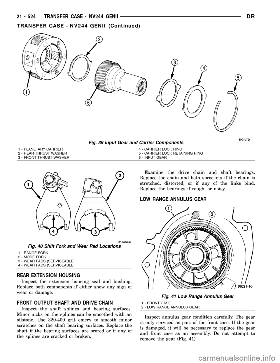
remove the gear (Fig. 41)
Fig. 39 Input Gear and Carrier Components
1 - PLANETARY CARRIER 4 - CARRIER LOCK RING
2 - REAR THRUST WASHER 5 - CARRIER LOCK RETAINING RING
3 - FRONT THRUST WASHER 6 - INPUT GEAR
Fig. 40 Shift Fork and Wear Pad Locations
1 - RANGE FORK
2 - MODE FORK
3 - WEAR PADS (SERVICEABLE)
4 - WEAR PADS (SERVICEABLE)
Fig. 41 Low Range Annulus Gear
1 - FRONT CASE
2 - LOW RANGE ANNULUS GEAR
21 - 524 TRANSFER CASE - NV244 GENIIDR
TRANSFER CASE - NV244 GENII (Continued)
Page 2229 of 2627
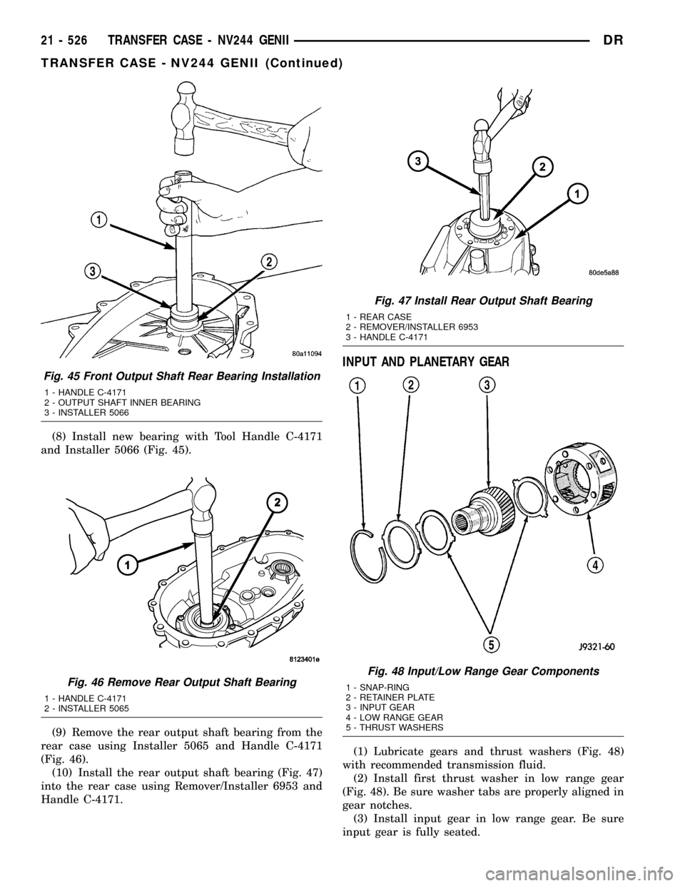
(8) Install new bearing with Tool Handle C-4171
and Installer 5066 (Fig. 45).
(9) Remove the rear output shaft bearing from the
rear case using Installer 5065 and Handle C-4171
(Fig. 46).
(10) Install the rear output shaft bearing (Fig. 47)
into the rear case using Remover/Installer 6953 and
Handle C-4171.
INPUT AND PLANETARY GEAR
(1) Lubricate gears and thrust washers (Fig. 48)
with recommended transmission fluid.
(2) Install first thrust washer in low range gear
(Fig. 48). Be sure washer tabs are properly aligned in
gear notches.
(3) Install input gear in low range gear. Be sure
input gear is fully seated.
Fig. 45 Front Output Shaft Rear Bearing Installation
1 - HANDLE C-4171
2 - OUTPUT SHAFT INNER BEARING
3 - INSTALLER 5066
Fig. 46 Remove Rear Output Shaft Bearing
1 - HANDLE C-4171
2 - INSTALLER 5065
Fig. 47 Install Rear Output Shaft Bearing
1 - REAR CASE
2 - REMOVER/INSTALLER 6953
3 - HANDLE C-4171
Fig. 48 Input/Low Range Gear Components
1 - SNAP-RING
2 - RETAINER PLATE
3 - INPUT GEAR
4 - LOW RANGE GEAR
5 - THRUST WASHERS
21 - 526 TRANSFER CASE - NV244 GENIIDR
TRANSFER CASE - NV244 GENII (Continued)
Page 2230 of 2627
(4) Install remaining thrust washer in low range
gear and on top of input gear. Be sure washer tabs
are properly aligned in gear notches.
(5) Install retainer on input gear and install snap-
ring.
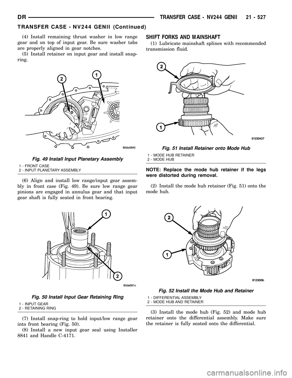
(6) Align and install low range/input gear assem-
bly in front case (Fig. 49). Be sure low range gear
pinions are engaged in annulus gear and that input
gear shaft is fully seated in front bearing.
(7) Install snap-ring to hold input/low range gear
into front bearing (Fig. 50).
(8) Install a new input gear seal using Installer
8841 and Handle C-4171.SHIFT FORKS AND MAINSHAFT
(1) Lubricate mainshaft splines with recommended
transmission fluid.
NOTE: Replace the mode hub retainer if the legs
were distorted during removal.
(2) Install the mode hub retainer (Fig. 51) onto the
mode hub.
(3) Install the mode hub (Fig. 52) and mode hub
retainer onto the differential assembly. Make sure
the retainer is fully seated onto the differential.
Fig. 49 Install Input Planetary Assembly
1 - FRONT CASE
2 - INPUT PLANETARY ASSEMBLY
Fig. 50 Install Input Gear Retaining Ring
1 - INPUT GEAR
2 - RETAINING RING
Fig. 51 Install Retainer onto Mode Hub
1 - MODE HUB RETAINER
2 - MODE HUB
Fig. 52 Install the Mode Hub and Retainer
1 - DIFFERENTIAL ASSEMBLY
2 - MODE HUB AND RETAINER
DRTRANSFER CASE - NV244 GENII 21 - 527
TRANSFER CASE - NV244 GENII (Continued)
Page 2257 of 2627
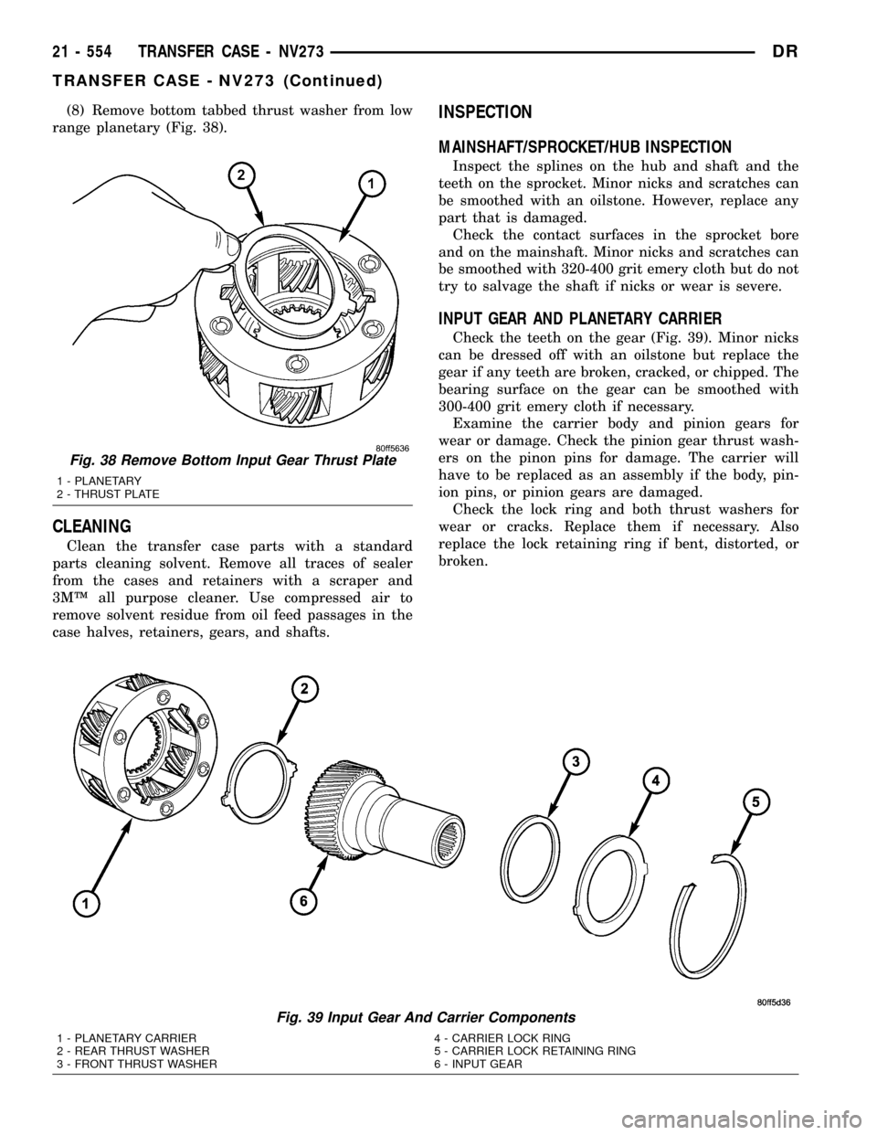
(8) Remove bottom tabbed thrust washer from low
range planetary (Fig. 38).
CLEANING
Clean the transfer case parts with a standard
parts cleaning solvent. Remove all traces of sealer
from the cases and retainers with a scraper and
3MŸ all purpose cleaner. Use compressed air to
remove solvent residue from oil feed passages in the
case halves, retainers, gears, and shafts.
INSPECTION
MAINSHAFT/SPROCKET/HUB INSPECTION
Inspect the splines on the hub and shaft and the
teeth on the sprocket. Minor nicks and scratches can
be smoothed with an oilstone. However, replace any
part that is damaged.
Check the contact surfaces in the sprocket bore
and on the mainshaft. Minor nicks and scratches can
be smoothed with 320-400 grit emery cloth but do not
try to salvage the shaft if nicks or wear is severe.
INPUT GEAR AND PLANETARY CARRIER
Check the teeth on the gear (Fig. 39). Minor nicks
can be dressed off with an oilstone but replace the
gear if any teeth are broken, cracked, or chipped. The
bearing surface on the gear can be smoothed with
300-400 grit emery cloth if necessary.
Examine the carrier body and pinion gears for
wear or damage. Check the pinion gear thrust wash-
ers on the pinon pins for damage. The carrier will
have to be replaced as an assembly if the body, pin-
ion pins, or pinion gears are damaged.
Check the lock ring and both thrust washers for
wear or cracks. Replace them if necessary. Also
replace the lock retaining ring if bent, distorted, or
broken.
Fig. 39 Input Gear And Carrier Components
1 - PLANETARY CARRIER 4 - CARRIER LOCK RING
2 - REAR THRUST WASHER 5 - CARRIER LOCK RETAINING RING
3 - FRONT THRUST WASHER 6 - INPUT GEAR
Fig. 38 Remove Bottom Input Gear Thrust Plate
1 - PLANETARY
2 - THRUST PLATE
21 - 554 TRANSFER CASE - NV273DR
TRANSFER CASE - NV273 (Continued)
Page 2262 of 2627
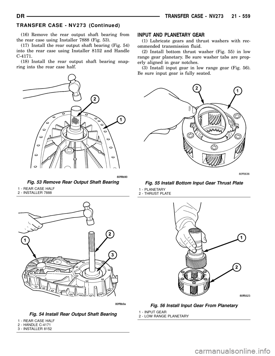
(16) Remove the rear output shaft bearing from
the rear case using Installer 7888 (Fig. 53).
(17) Install the rear output shaft bearing (Fig. 54)
into the rear case using Installer 8152 and Handle
C-4171.
(18) Install the rear output shaft bearing snap-
ring into the rear case half.INPUT AND PLANETARY GEAR
(1) Lubricate gears and thrust washers with rec-
ommended transmission fluid.
(2) Install bottom thrust washer (Fig. 55) in low
range gear planetary. Be sure washer tabs are prop-
erly aligned in gear notches.
(3) Install input gear in low range gear (Fig. 56).
Be sure input gear is fully seated.
Fig. 53 Remove Rear Output Shaft Bearing
1 - REAR CASE HALF
2 - INSTALLER 7888
Fig. 54 Install Rear Output Shaft Bearing
1 - REAR CASE HALF
2 - HANDLE C-4171
3 - INSTALLER 8152
Fig. 55 Install Bottom Input Gear Thrust Plate
1 - PLANETARY
2 - THRUST PLATE
Fig. 56 Install Input Gear From Planetary
1 - INPUT GEAR
2 - LOW RANGE PLANETARY
DRTRANSFER CASE - NV273 21 - 559
TRANSFER CASE - NV273 (Continued)
Page 2263 of 2627
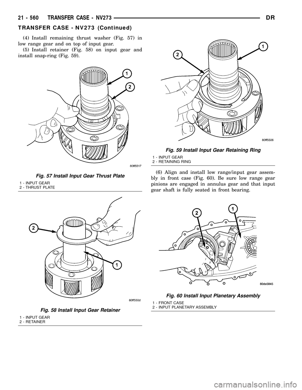
(4) Install remaining thrust washer (Fig. 57) in
low range gear and on top of input gear.
(5) Install retainer (Fig. 58) on input gear and
install snap-ring (Fig. 59).
(6) Align and install low range/input gear assem-
bly in front case (Fig. 60). Be sure low range gear
pinions are engaged in annulus gear and that input
gear shaft is fully seated in front bearing.
Fig. 60 Install Input Planetary Assembly
1 - FRONT CASE
2 - INPUT PLANETARY ASSEMBLY
Fig. 57 Install Input Gear Thrust Plate
1 - INPUT GEAR
2 - THRUST PLATE
Fig. 58 Install Input Gear Retainer
1 - INPUT GEAR
2 - RETAINER
Fig. 59 Install Input Gear Retaining Ring
1 - INPUT GEAR
2 - RETAINING RING
21 - 560 TRANSFER CASE - NV273DR
TRANSFER CASE - NV273 (Continued)
Page 2292 of 2627
center caps for more information refer to Owner's
Manual.
The tires on both wheels must be completely raised
off the ground when tightening the lug nuts. This
will ensure correct wheel centering and maximum
wheel clamping.
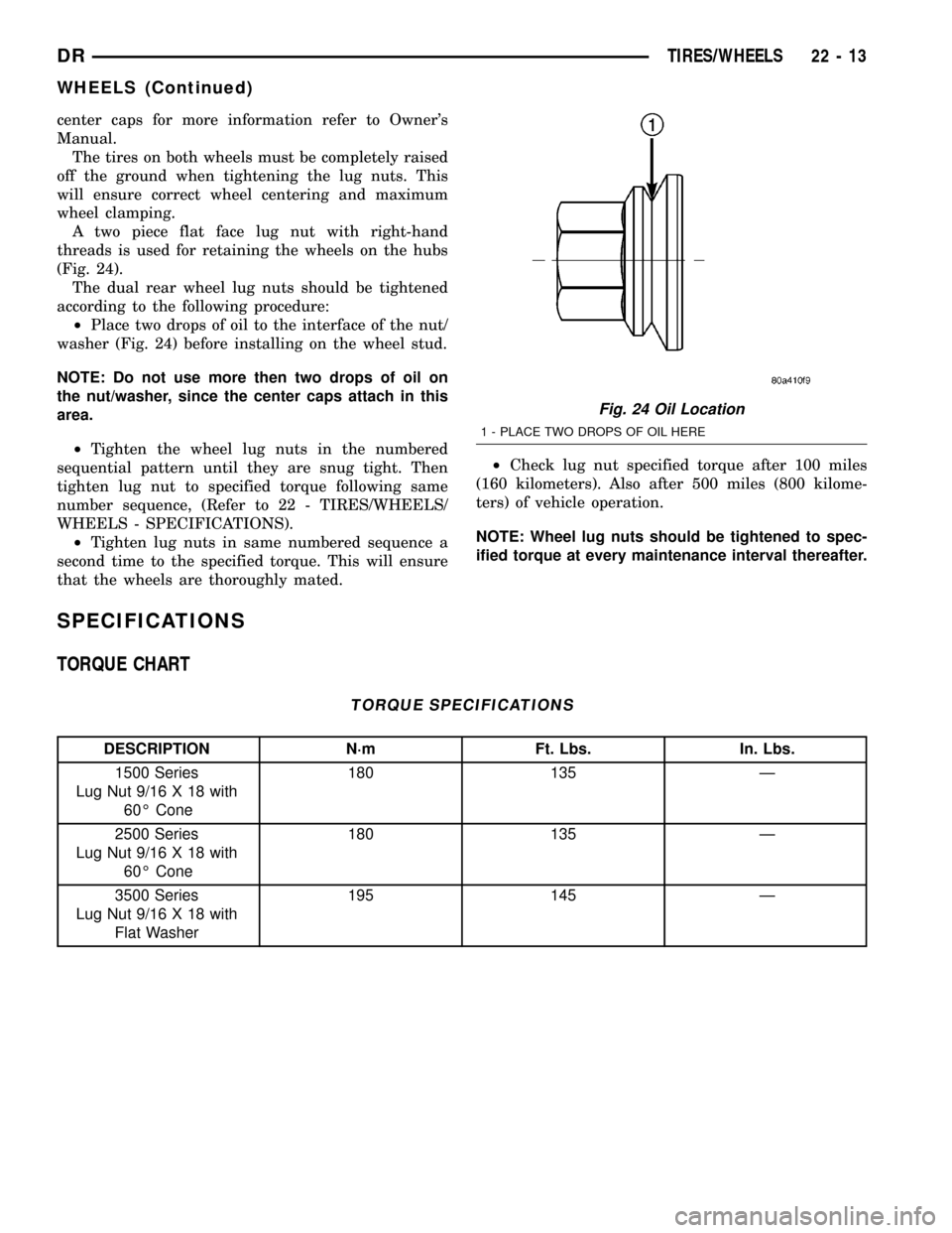
A two piece flat face lug nut with right-hand
threads is used for retaining the wheels on the hubs
(Fig. 24).
The dual rear wheel lug nuts should be tightened
according to the following procedure:
²Place two drops of oil to the interface of the nut/
washer (Fig. 24) before installing on the wheel stud.
NOTE: Do not use more then two drops of oil on
the nut/washer, since the center caps attach in this
area.
²Tighten the wheel lug nuts in the numbered
sequential pattern until they are snug tight. Then
tighten lug nut to specified torque following same
number sequence, (Refer to 22 - TIRES/WHEELS/
WHEELS - SPECIFICATIONS).
²Tighten lug nuts in same numbered sequence a
second time to the specified torque. This will ensure
that the wheels are thoroughly mated.²Check lug nut specified torque after 100 miles
(160 kilometers). Also after 500 miles (800 kilome-
ters) of vehicle operation.
NOTE: Wheel lug nuts should be tightened to spec-
ified torque at every maintenance interval thereafter.
SPECIFICATIONS
TORQUE CHART
TORQUE SPECIFICATIONS
DESCRIPTION N´m Ft. Lbs. In. Lbs.
1500 Series
Lug Nut 9/16 X 18 with
60É Cone180 135 Ð
2500 Series
Lug Nut 9/16 X 18 with
60É Cone180 135 Ð
3500 Series
Lug Nut 9/16 X 18 with
Flat Washer195 145 Ð
Fig. 24 Oil Location
1 - PLACE TWO DROPS OF OIL HERE
DRTIRES/WHEELS 22 - 13
WHEELS (Continued)
Page 2293 of 2627
STUDS
REMOVAL
(1) Raise and support the vehicle.
(2) Remove the wheel and tire assembly.
(3) Remove the brake caliper, caliper adapter and
rotor, (Refer to 5 - BRAKES/HYDRAULIC/MECHAN-
ICAL/ROTORS - REMOVAL).
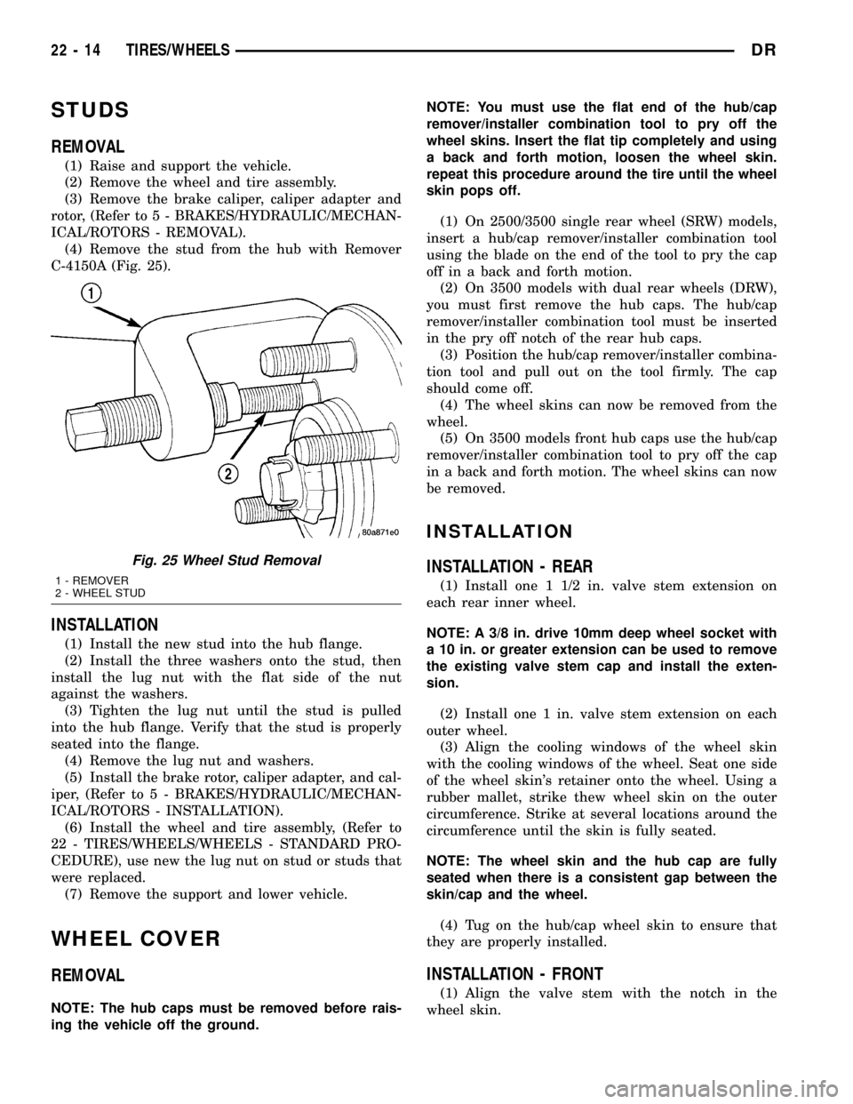
(4) Remove the stud from the hub with Remover
C-4150A (Fig. 25).
INSTALLATION
(1) Install the new stud into the hub flange.
(2) Install the three washers onto the stud, then
install the lug nut with the flat side of the nut
against the washers.
(3) Tighten the lug nut until the stud is pulled
into the hub flange. Verify that the stud is properly
seated into the flange.
(4) Remove the lug nut and washers.
(5) Install the brake rotor, caliper adapter, and cal-
iper, (Refer to 5 - BRAKES/HYDRAULIC/MECHAN-
ICAL/ROTORS - INSTALLATION).
(6) Install the wheel and tire assembly, (Refer to
22 - TIRES/WHEELS/WHEELS - STANDARD PRO-
CEDURE), use new the lug nut on stud or studs that
were replaced.
(7) Remove the support and lower vehicle.
WHEEL COVER
REMOVAL
NOTE: The hub caps must be removed before rais-
ing the vehicle off the ground.NOTE: You must use the flat end of the hub/cap
remover/installer combination tool to pry off the
wheel skins. Insert the flat tip completely and using
a back and forth motion, loosen the wheel skin.
repeat this procedure around the tire until the wheel
skin pops off.
(1) On 2500/3500 single rear wheel (SRW) models,
insert a hub/cap remover/installer combination tool
using the blade on the end of the tool to pry the cap
off in a back and forth motion.
(2) On 3500 models with dual rear wheels (DRW),
you must first remove the hub caps. The hub/cap
remover/installer combination tool must be inserted
in the pry off notch of the rear hub caps.
(3) Position the hub/cap remover/installer combina-
tion tool and pull out on the tool firmly. The cap
should come off.
(4) The wheel skins can now be removed from the
wheel.
(5) On 3500 models front hub caps use the hub/cap
remover/installer combination tool to pry off the cap
in a back and forth motion. The wheel skins can now
be removed.
INSTALLATION
INSTALLATION - REAR
(1) Install one 1 1/2 in. valve stem extension on
each rear inner wheel.
NOTE: A 3/8 in. drive 10mm deep wheel socket with
a 10 in. or greater extension can be used to remove
the existing valve stem cap and install the exten-
sion.
(2) Install one 1 in. valve stem extension on each
outer wheel.
(3) Align the cooling windows of the wheel skin
with the cooling windows of the wheel. Seat one side
of the wheel skin's retainer onto the wheel. Using a
rubber mallet, strike thew wheel skin on the outer
circumference. Strike at several locations around the
circumference until the skin is fully seated.
NOTE: The wheel skin and the hub cap are fully
seated when there is a consistent gap between the
skin/cap and the wheel.
(4) Tug on the hub/cap wheel skin to ensure that
they are properly installed.
INSTALLATION - FRONT
(1) Align the valve stem with the notch in the
wheel skin.
Fig. 25 Wheel Stud Removal
1 - REMOVER
2 - WHEEL STUD
22 - 14 TIRES/WHEELSDR