1998 DODGE RAM 1500 Rear seat
[x] Cancel search: Rear seatPage 2380 of 2627
SEAT CUSHION FRAME - REAR
REMOVAL
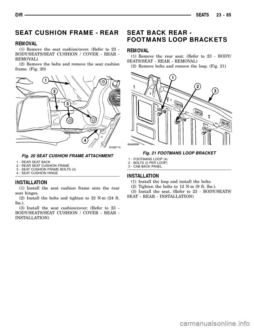
(1) Remove the seat cushion/cover. (Refer to 23 -
BODY/SEATS/SEAT CUSHION / COVER - REAR -
REMOVAL)
(2) Remove the bolts and remove the seat cushion
frame. (Fig. 20)
INSTALLATION
(1) Install the seat cushion frame onto the rear
seat hinges.
(2) Install the bolts and tighten to 32 N´m (24 ft.
lbs.).
(3) Install the seat cushion/cover. (Refer to 23 -
BODY/SEATS/SEAT CUSHION / COVER - REAR -
INSTALLATION)
SEAT BACK REAR -
FOOTMANS LOOP BRACKETS
REMOVAL
(1) Remove the rear seat. (Refer to 23 - BODY/
SEATS/SEAT - REAR - REMOVAL)
(2) Remove bolts and remove the loop. (Fig. 21)
INSTALLATION
(1) Install the loop and install the bolts.
(2) Tighten the bolts to 12 N´m (9 ft. lbs.).
(3) Install the seat. (Refer to 23 - BODY/SEATS/
SEAT - REAR - INSTALLATION)
Fig. 20 SEAT CUSHION FRAME ATTACHMENT
1 - REAR SEAT BACK
2 - REAR SEAT CUSHION FRAME
3 - SEAT CUSHION FRAME BOLTS (4)
4 - SEAT CUSHION HINGE
Fig. 21 FOOTMANS LOOP BRACKET
1 - FOOTMANS LOOP (4)
2 - BOLTS (2 PER LOOP)
3 - CAB BACK PANEL
DRSEATS 23 - 85
Page 2386 of 2627
WEATHERSTRIP/SEALS
TABLE OF CONTENTS
page page
A-PILLAR WEATHERSTRIP RETAINER
REMOVAL.............................91
INSTALLATION.........................91
DRIP RAIL WEATHERSTRIP
REMOVAL.............................91
INSTALLATION.........................91
DOOR OPENING SEAL
REMOVAL.............................92
INSTALLATION.........................92
DRIP RAIL WEATHERSTRIP RETAINER
REMOVAL.............................92
INSTALLATION.........................92
FRONT DOOR GLASS RUN WEATHERSTRIP
REMOVAL.............................92
INSTALLATION.........................92FRONT DOOR OUTER BELT MOLDING
REMOVAL.............................92
INSTALLATION.........................93
FRONT DOOR INNER BELT MOLDING
REMOVAL.............................93
INSTALLATION.........................93
REAR DOOR GLASS RUN WEATHERSTRIP
REMOVAL.............................93
INSTALLATION.........................93
REAR DOOR OUTER BELT MOLDING
REMOVAL.............................93
INSTALLATION.........................94
REAR DOOR INNER BELT MOLDING
REMOVAL.............................94
INSTALLATION.........................94
A-PILLAR WEATHERSTRIP
RETAINER
REMOVAL
(1) Remove the drip rail weatherstrip retainer.
(Refer to 23 - BODY/WEATHERSTRIP/SEALS/DRIP
RAIL WEATHERSTRIP - REMOVAL)
(2) Remove the five screws and remove the weath-
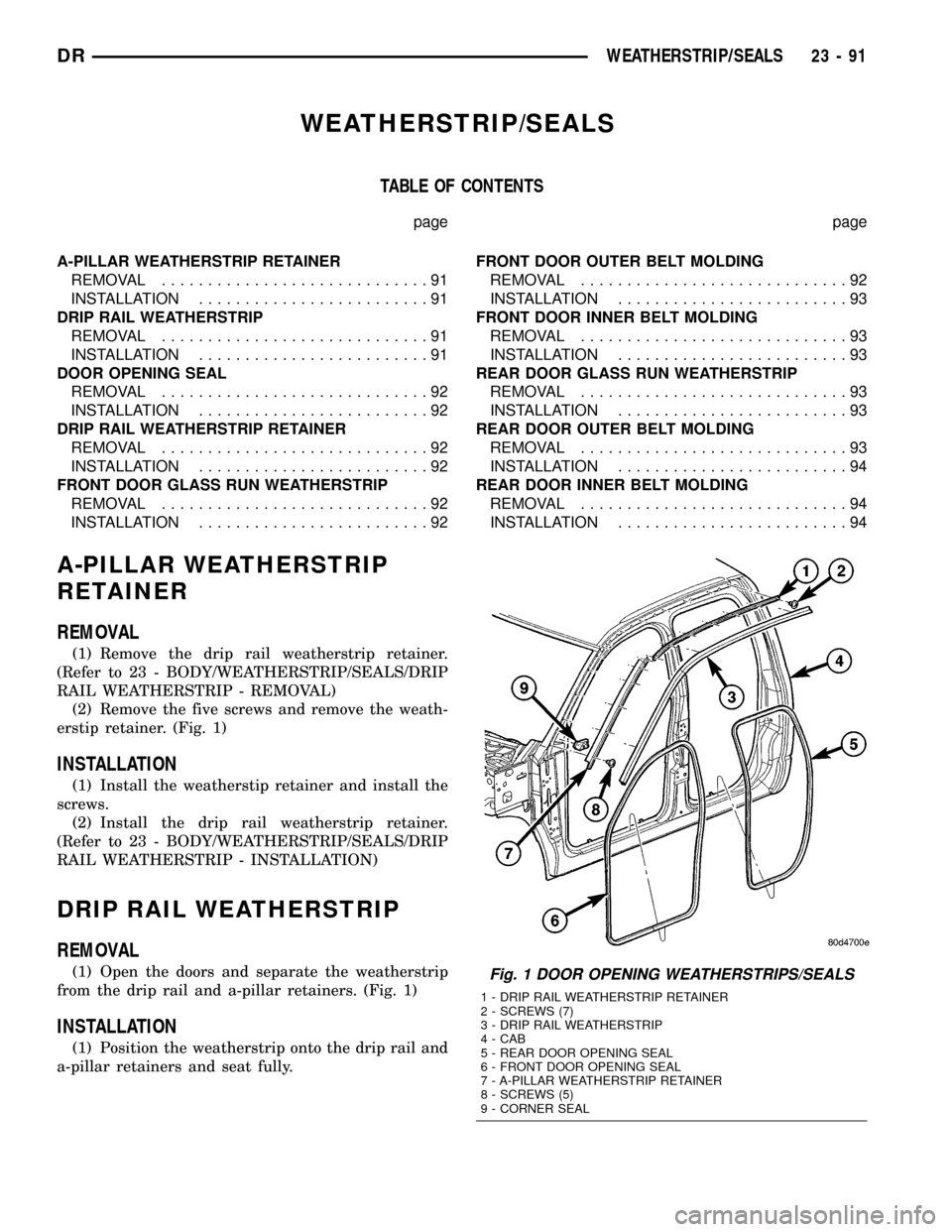
erstip retainer. (Fig. 1)
INSTALLATION
(1) Install the weatherstip retainer and install the
screws.
(2) Install the drip rail weatherstrip retainer.
(Refer to 23 - BODY/WEATHERSTRIP/SEALS/DRIP
RAIL WEATHERSTRIP - INSTALLATION)
DRIP RAIL WEATHERSTRIP
REMOVAL
(1) Open the doors and separate the weatherstrip
from the drip rail and a-pillar retainers. (Fig. 1)
INSTALLATION
(1) Position the weatherstrip onto the drip rail and
a-pillar retainers and seat fully.
Fig. 1 DOOR OPENING WEATHERSTRIPS/SEALS
1 - DRIP RAIL WEATHERSTRIP RETAINER
2 - SCREWS (7)
3 - DRIP RAIL WEATHERSTRIP
4 - CAB
5 - REAR DOOR OPENING SEAL
6 - FRONT DOOR OPENING SEAL
7 - A-PILLAR WEATHERSTRIP RETAINER
8 - SCREWS (5)
9 - CORNER SEAL
DRWEATHERSTRIP/SEALS 23 - 91
Page 2387 of 2627

DOOR OPENING SEAL
REMOVAL
FRONT DOOR SEAL
(1) Remove the cowl trim panel. (Refer to 23 -
BODY/INTERIOR/COWL TRIM - REMOVAL)
(2) Remove the lower b-pillar trim panel. (Refer to
23 - BODY/INTERIOR/B-PILLAR LOWER TRIM -
REMOVAL)
(3) Separate the door opening seal from the door
opening flange. (Fig. 1)
REAR DOOR SEAL
(1) Remove the lower b-pillar trim panel. (Refer to
23 - BODY/INTERIOR/B-PILLAR LOWER TRIM -
REMOVAL)
(2) Remove the lower c-pillar trim. (Refer to 23 -
BODY/INTERIOR/C-PILLAR TRIM - REMOVAL)
(3) Separate the door opening seal from the door
opening flange. (Fig. 1)
INSTALLATION
FRONT DOOR SEAL
(1) Position the seal to the bottom of the door
opening, with bulb facing outboard, starting the
installation at the center of the lower flange. Press
the seal onto the sill flange and work around the
perimeter of the door opening until fully seated.
Work in one direction, smoothing the seal to avoid
puckers or wrinkles.
(2) Install the lower b-pillar trim. (Refer to 23 -
BODY/INTERIOR/B-PILLAR LOWER TRIM -
INSTALLATION)
(3) Install the cowl trim panel. (Refer to 23 -
BODY/INTERIOR/COWL TRIM - INSTALLATION)
(4) When installing a new weatherstrip on the
front door opening, remove the tear strip starting at
the splice and moving around the front of the door to
the back of the opening.
REAR DOOR SEAL
(1) Position the seal to the bottom of the door
opening, with bulb facing outboard, starting the
installation at the center of the lower flange. Press
the seal onto the sill flange and work around the
perimeter of the door opening until fully seated.
Work in one direction, smoothing the seal to avoid
puckers or wrinkles.
(2) Install the lower c-pillar trim. (Refer to 23 -
BODY/INTERIOR/C-PILLAR TRIM - INSTALLA-
TION)
(3) Install the lower b-pillar trim. (Refer to 23 -
BODY/INTERIOR/B-PILLAR LOWER TRIM -
INSTALLATION)(4) When installing a new weatherstrip on the rear
door opening, remove the tear strip starting at the
splice and moving around the back of the door to the
front of the opening.
DRIP RAIL WEATHERSTRIP
RETAINER
REMOVAL
(1) Separate the drip rail weatherstrip from the
weatherstrip retainer. (Fig. 1)
(2) Remove the seven screws and remove the
retainer.
INSTALLATION
(1) Install the weatherstrip retainer and install
the seven screws.
(2) Position the weatherstrip over the retainer
flange and seat fully.
FRONT DOOR GLASS RUN
WEATHERSTRIP
REMOVAL
(1) Remove the door glass. (Refer to 23 - BODY/
DOOR - FRONT/DOOR GLASS - REMOVAL)
(2) Separate the weatherstrip out of the door
frame and remove through the window opening. (Fig.
2)
INSTALLATION
NOTE: A mixture of soap and water may be used to
aid installation of the weatherstrip into the corners.
(1) Position the glass run weatherstrip into the
door through the window opening.
(2) Position the weatherstrip into the upper cor-
ners and seat firmly.
(3) From back to front, seat the weatherstrip
between the corners and then down the sides firmly
(4) Install the door glass. (Refer to 23 - BODY/
DOOR - FRONT/DOOR GLASS - INSTALLATION)
FRONT DOOR OUTER BELT
MOLDING
REMOVAL
(1) Remove the screw and separate the belt mold-
ing from the door flange from the back to the front.
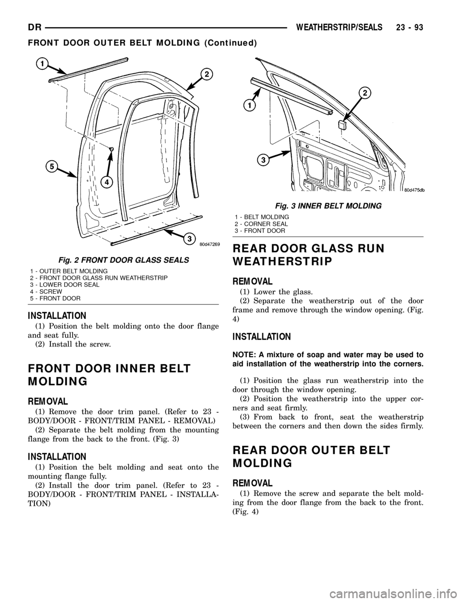
(Fig. 2)
23 - 92 WEATHERSTRIP/SEALSDR
Page 2388 of 2627
INSTALLATION
(1) Position the belt molding onto the door flange
and seat fully.
(2) Install the screw.
FRONT DOOR INNER BELT
MOLDING
REMOVAL
(1) Remove the door trim panel. (Refer to 23 -
BODY/DOOR - FRONT/TRIM PANEL - REMOVAL)
(2) Separate the belt molding from the mounting
flange from the back to the front. (Fig. 3)
INSTALLATION
(1) Position the belt molding and seat onto the
mounting flange fully.
(2) Install the door trim panel. (Refer to 23 -
BODY/DOOR - FRONT/TRIM PANEL - INSTALLA-
TION)
REAR DOOR GLASS RUN
WEATHERSTRIP
REMOVAL
(1) Lower the glass.
(2) Separate the weatherstrip out of the door
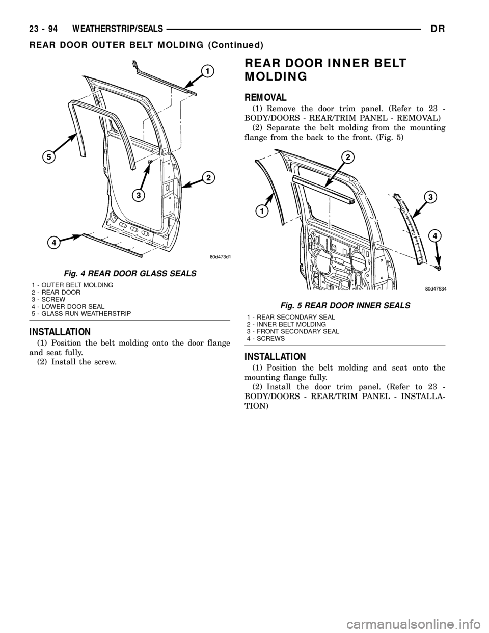
frame and remove through the window opening. (Fig.
4)
INSTALLATION
NOTE: A mixture of soap and water may be used to
aid installation of the weatherstrip into the corners.
(1) Position the glass run weatherstrip into the
door through the window opening.
(2) Position the weatherstrip into the upper cor-
ners and seat firmly.
(3) From back to front, seat the weatherstrip
between the corners and then down the sides firmly.
REAR DOOR OUTER BELT
MOLDING
REMOVAL
(1) Remove the screw and separate the belt mold-
ing from the door flange from the back to the front.
(Fig. 4)
Fig. 2 FRONT DOOR GLASS SEALS
1 - OUTER BELT MOLDING
2 - FRONT DOOR GLASS RUN WEATHERSTRIP
3 - LOWER DOOR SEAL
4 - SCREW
5 - FRONT DOOR
Fig. 3 INNER BELT MOLDING
1 - BELT MOLDING
2 - CORNER SEAL
3 - FRONT DOOR
DRWEATHERSTRIP/SEALS 23 - 93
FRONT DOOR OUTER BELT MOLDING (Continued)
Page 2389 of 2627
INSTALLATION
(1) Position the belt molding onto the door flange
and seat fully.
(2) Install the screw.
REAR DOOR INNER BELT
MOLDING
REMOVAL
(1) Remove the door trim panel. (Refer to 23 -
BODY/DOORS - REAR/TRIM PANEL - REMOVAL)
(2) Separate the belt molding from the mounting
flange from the back to the front. (Fig. 5)
INSTALLATION
(1) Position the belt molding and seat onto the
mounting flange fully.
(2) Install the door trim panel. (Refer to 23 -
BODY/DOORS - REAR/TRIM PANEL - INSTALLA-
TION)
Fig. 4 REAR DOOR GLASS SEALS
1 - OUTER BELT MOLDING
2 - REAR DOOR
3 - SCREW
4 - LOWER DOOR SEAL
5 - GLASS RUN WEATHERSTRIP
Fig. 5 REAR DOOR INNER SEALS
1 - REAR SECONDARY SEAL
2 - INNER BELT MOLDING
3 - FRONT SECONDARY SEAL
4 - SCREWS
23 - 94 WEATHERSTRIP/SEALSDR
REAR DOOR OUTER BELT MOLDING (Continued)
Page 2407 of 2627
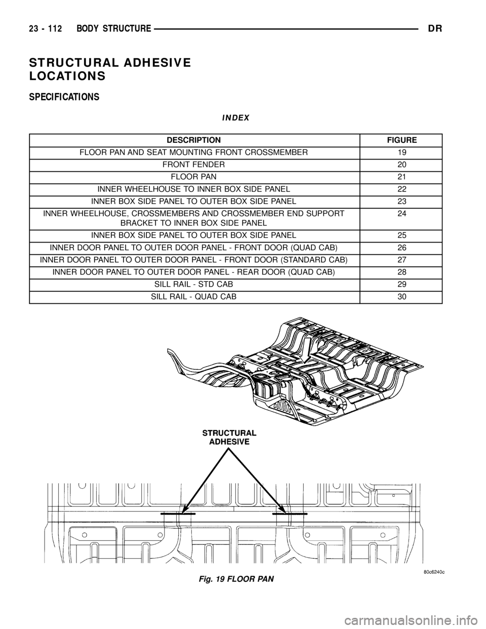
STRUCTURAL ADHESIVE
LOCATIONS
SPECIFICATIONS
INDEX
DESCRIPTION FIGURE
FLOOR PAN AND SEAT MOUNTING FRONT CROSSMEMBER 19
FRONT FENDER 20
FLOOR PAN 21
INNER WHEELHOUSE TO INNER BOX SIDE PANEL 22
INNER BOX SIDE PANEL TO OUTER BOX SIDE PANEL 23
INNER WHEELHOUSE, CROSSMEMBERS AND CROSSMEMBER END SUPPORT
BRACKET TO INNER BOX SIDE PANEL24
INNER BOX SIDE PANEL TO OUTER BOX SIDE PANEL 25
INNER DOOR PANEL TO OUTER DOOR PANEL - FRONT DOOR (QUAD CAB) 26
INNER DOOR PANEL TO OUTER DOOR PANEL - FRONT DOOR (STANDARD CAB) 27
INNER DOOR PANEL TO OUTER DOOR PANEL - REAR DOOR (QUAD CAB) 28
SILL RAIL - STD CAB 29
SILL RAIL - QUAD CAB 30
Fig. 19 FLOOR PAN
23 - 112 BODY STRUCTUREDR
Page 2415 of 2627
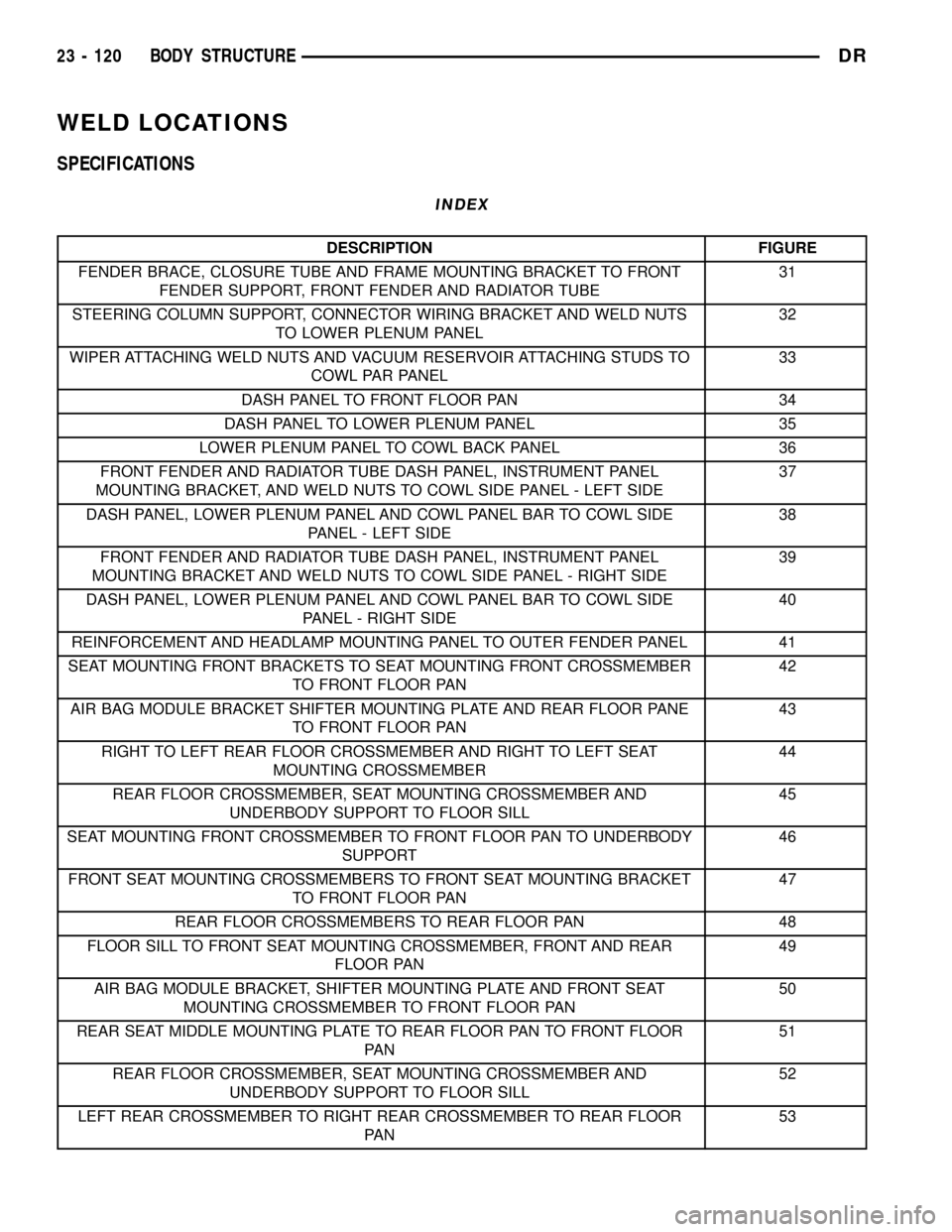
WELD LOCATIONS
SPECIFICATIONS
INDEX
DESCRIPTION FIGURE
FENDER BRACE, CLOSURE TUBE AND FRAME MOUNTING BRACKET TO FRONT
FENDER SUPPORT, FRONT FENDER AND RADIATOR TUBE31
STEERING COLUMN SUPPORT, CONNECTOR WIRING BRACKET AND WELD NUTS
TO LOWER PLENUM PANEL32
WIPER ATTACHING WELD NUTS AND VACUUM RESERVOIR ATTACHING STUDS TO
COWL PAR PANEL33
DASH PANEL TO FRONT FLOOR PAN 34
DASH PANEL TO LOWER PLENUM PANEL 35
LOWER PLENUM PANEL TO COWL BACK PANEL 36
FRONT FENDER AND RADIATOR TUBE DASH PANEL, INSTRUMENT PANEL
MOUNTING BRACKET, AND WELD NUTS TO COWL SIDE PANEL - LEFT SIDE37
DASH PANEL, LOWER PLENUM PANEL AND COWL PANEL BAR TO COWL SIDE
PANEL - LEFT SIDE38
FRONT FENDER AND RADIATOR TUBE DASH PANEL, INSTRUMENT PANEL
MOUNTING BRACKET AND WELD NUTS TO COWL SIDE PANEL - RIGHT SIDE39
DASH PANEL, LOWER PLENUM PANEL AND COWL PANEL BAR TO COWL SIDE
PANEL - RIGHT SIDE40
REINFORCEMENT AND HEADLAMP MOUNTING PANEL TO OUTER FENDER PANEL 41
SEAT MOUNTING FRONT BRACKETS TO SEAT MOUNTING FRONT CROSSMEMBER
TO FRONT FLOOR PAN42
AIR BAG MODULE BRACKET SHIFTER MOUNTING PLATE AND REAR FLOOR PANE
TO FRONT FLOOR PAN43
RIGHT TO LEFT REAR FLOOR CROSSMEMBER AND RIGHT TO LEFT SEAT
MOUNTING CROSSMEMBER44
REAR FLOOR CROSSMEMBER, SEAT MOUNTING CROSSMEMBER AND
UNDERBODY SUPPORT TO FLOOR SILL45
SEAT MOUNTING FRONT CROSSMEMBER TO FRONT FLOOR PAN TO UNDERBODY
SUPPORT46
FRONT SEAT MOUNTING CROSSMEMBERS TO FRONT SEAT MOUNTING BRACKET
TO FRONT FLOOR PAN47
REAR FLOOR CROSSMEMBERS TO REAR FLOOR PAN 48
FLOOR SILL TO FRONT SEAT MOUNTING CROSSMEMBER, FRONT AND REAR
FLOOR PAN49
AIR BAG MODULE BRACKET, SHIFTER MOUNTING PLATE AND FRONT SEAT
MOUNTING CROSSMEMBER TO FRONT FLOOR PAN50
REAR SEAT MIDDLE MOUNTING PLATE TO REAR FLOOR PAN TO FRONT FLOOR
PA N51
REAR FLOOR CROSSMEMBER, SEAT MOUNTING CROSSMEMBER AND
UNDERBODY SUPPORT TO FLOOR SILL52
LEFT REAR CROSSMEMBER TO RIGHT REAR CROSSMEMBER TO REAR FLOOR
PA N53
23 - 120 BODY STRUCTUREDR
Page 2416 of 2627
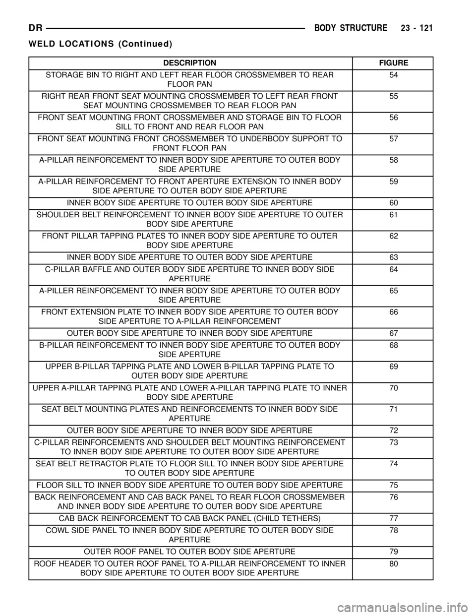
DESCRIPTION FIGURE
STORAGE BIN TO RIGHT AND LEFT REAR FLOOR CROSSMEMBER TO REAR
FLOOR PAN54
RIGHT REAR FRONT SEAT MOUNTING CROSSMEMBER TO LEFT REAR FRONT
SEAT MOUNTING CROSSMEMBER TO REAR FLOOR PAN55
FRONT SEAT MOUNTING FRONT CROSSMEMBER AND STORAGE BIN TO FLOOR
SILL TO FRONT AND REAR FLOOR PAN56
FRONT SEAT MOUNTING FRONT CROSSMEMBER TO UNDERBODY SUPPORT TO
FRONT FLOOR PAN57
A-PILLAR REINFORCEMENT TO INNER BODY SIDE APERTURE TO OUTER BODY
SIDE APERTURE58
A-PILLAR REINFORCEMENT TO FRONT APERTURE EXTENSION TO INNER BODY
SIDE APERTURE TO OUTER BODY SIDE APERTURE59
INNER BODY SIDE APERTURE TO OUTER BODY SIDE APERTURE 60
SHOULDER BELT REINFORCEMENT TO INNER BODY SIDE APERTURE TO OUTER
BODY SIDE APERTURE61
FRONT PILLAR TAPPING PLATES TO INNER BODY SIDE APERTURE TO OUTER
BODY SIDE APERTURE62
INNER BODY SIDE APERTURE TO OUTER BODY SIDE APERTURE 63
C-PILLAR BAFFLE AND OUTER BODY SIDE APERTURE TO INNER BODY SIDE
APERTURE64
A-PILLER REINFORCEMENT TO INNER BODY SIDE APERTURE TO OUTER BODY
SIDE APERTURE65
FRONT EXTENSION PLATE TO INNER BODY SIDE APERTURE TO OUTER BODY
SIDE APERTURE TO A-PILLAR REINFORCEMENT66
OUTER BODY SIDE APERTURE TO INNER BODY SIDE APERTURE 67
B-PILLAR REINFORCEMENT TO INNER BODY SIDE APERTURE TO OUTER BODY
SIDE APERTURE68
UPPER B-PILLAR TAPPING PLATE AND LOWER B-PILLAR TAPPING PLATE TO
OUTER BODY SIDE APERTURE69
UPPER A-PILLAR TAPPING PLATE AND LOWER A-PILLAR TAPPING PLATE TO INNER
BODY SIDE APERTURE70
SEAT BELT MOUNTING PLATES AND REINFORCEMENTS TO INNER BODY SIDE
APERTURE71
OUTER BODY SIDE APERTURE TO INNER BODY SIDE APERTURE 72
C-PILLAR REINFORCEMENTS AND SHOULDER BELT MOUNTING REINFORCEMENT
TO INNER BODY SIDE APERTURE TO OUTER BODY SIDE APERTURE73
SEAT BELT RETRACTOR PLATE TO FLOOR SILL TO INNER BODY SIDE APERTURE
TO OUTER BODY SIDE APERTURE74
FLOOR SILL TO INNER BODY SIDE APERTURE TO OUTER BODY SIDE APERTURE 75
BACK REINFORCEMENT AND CAB BACK PANEL TO REAR FLOOR CROSSMEMBER
AND INNER BODY SIDE APERTURE TO OUTER BODY SIDE APERTURE76
CAB BACK REINFORCEMENT TO CAB BACK PANEL (CHILD TETHERS) 77
COWL SIDE PANEL TO INNER BODY SIDE APERTURE TO OUTER BODY SIDE
APERTURE78
OUTER ROOF PANEL TO OUTER BODY SIDE APERTURE 79
ROOF HEADER TO OUTER ROOF PANEL TO A-PILLAR REINFORCEMENT TO INNER
BODY SIDE APERTURE TO OUTER BODY SIDE APERTURE80
DRBODY STRUCTURE 23 - 121
WELD LOCATIONS (Continued)