1998 DODGE RAM 1500 Rear seat
[x] Cancel search: Rear seatPage 2250 of 2627
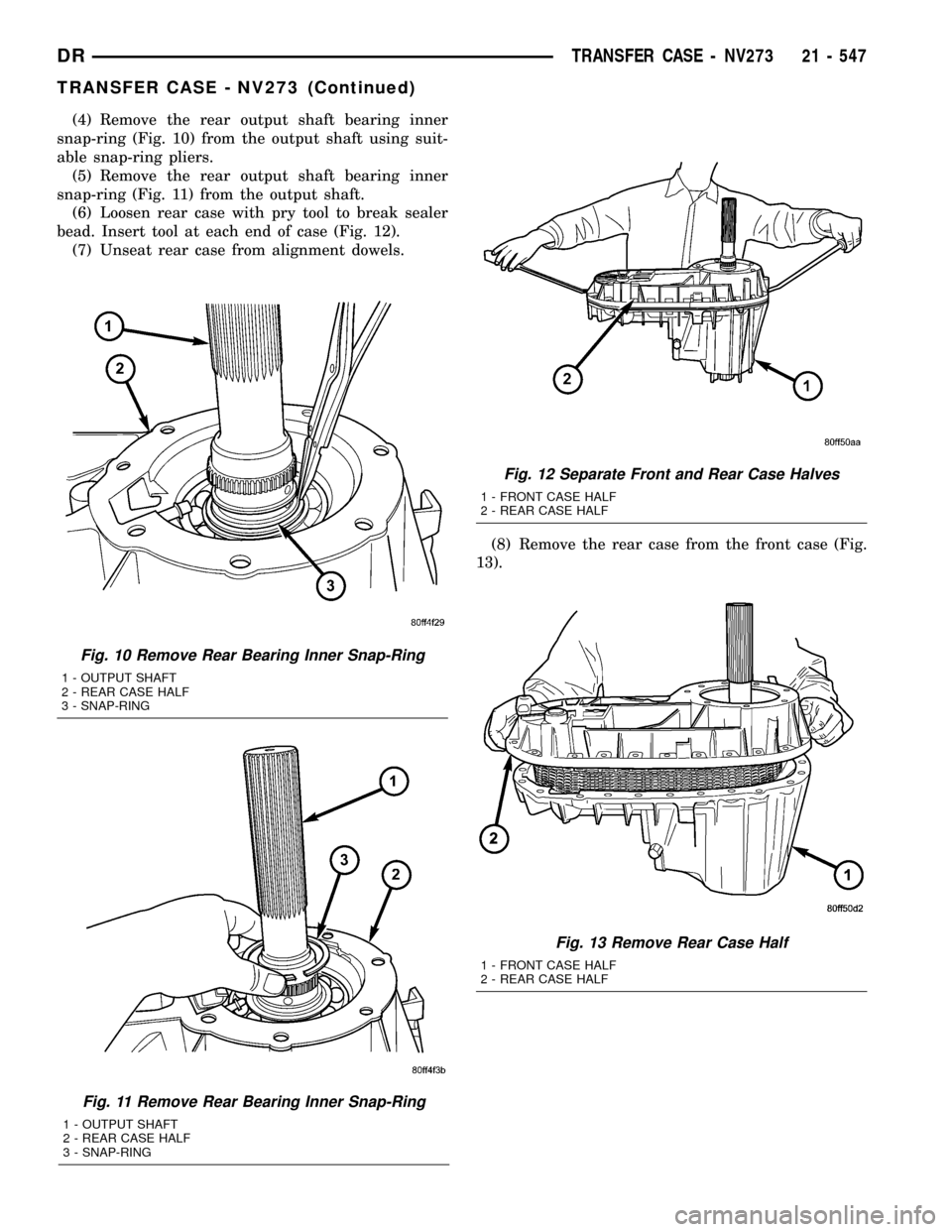
(4) Remove the rear output shaft bearing inner
snap-ring (Fig. 10) from the output shaft using suit-
able snap-ring pliers.
(5) Remove the rear output shaft bearing inner
snap-ring (Fig. 11) from the output shaft.
(6) Loosen rear case with pry tool to break sealer
bead. Insert tool at each end of case (Fig. 12).
(7) Unseat rear case from alignment dowels.
(8) Remove the rear case from the front case (Fig.
13).
Fig. 10 Remove Rear Bearing Inner Snap-Ring
1 - OUTPUT SHAFT
2 - REAR CASE HALF
3 - SNAP-RING
Fig. 11 Remove Rear Bearing Inner Snap-Ring
1 - OUTPUT SHAFT
2 - REAR CASE HALF
3 - SNAP-RING
Fig. 12 Separate Front and Rear Case Halves
1 - FRONT CASE HALF
2 - REAR CASE HALF
Fig. 13 Remove Rear Case Half
1 - FRONT CASE HALF
2 - REAR CASE HALF
DRTRANSFER CASE - NV273 21 - 547
TRANSFER CASE - NV273 (Continued)
Page 2260 of 2627
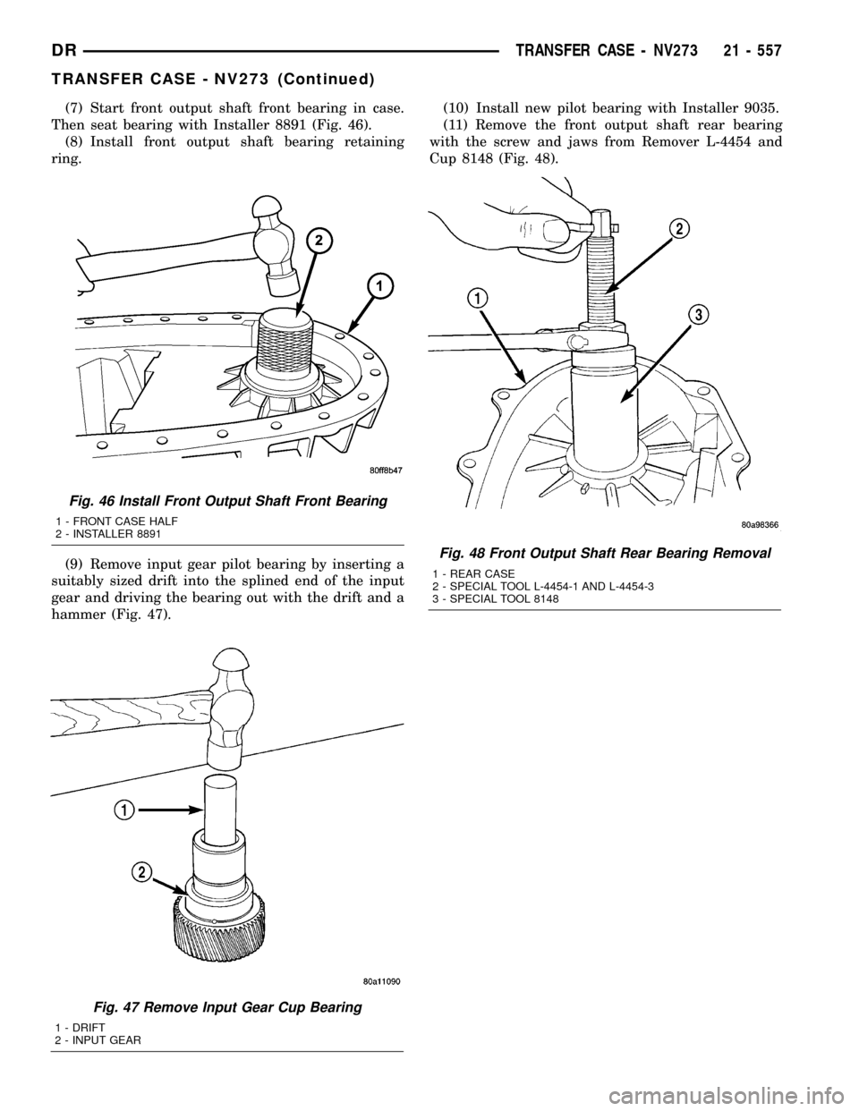
(7) Start front output shaft front bearing in case.
Then seat bearing with Installer 8891 (Fig. 46).
(8) Install front output shaft bearing retaining
ring.
(9) Remove input gear pilot bearing by inserting a
suitably sized drift into the splined end of the input
gear and driving the bearing out with the drift and a
hammer (Fig. 47).(10) Install new pilot bearing with Installer 9035.
(11) Remove the front output shaft rear bearing
with the screw and jaws from Remover L-4454 and
Cup 8148 (Fig. 48).
Fig. 47 Remove Input Gear Cup Bearing
1 - DRIFT
2 - INPUT GEAR
Fig. 48 Front Output Shaft Rear Bearing Removal
1 - REAR CASE
2 - SPECIAL TOOL L-4454-1 AND L-4454-3
3 - SPECIAL TOOL 8148
Fig. 46 Install Front Output Shaft Front Bearing
1 - FRONT CASE HALF
2 - INSTALLER 8891
DRTRANSFER CASE - NV273 21 - 557
TRANSFER CASE - NV273 (Continued)
Page 2261 of 2627
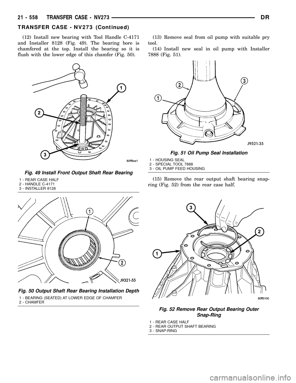
(12) Install new bearing with Tool Handle C-4171
and Installer 8128 (Fig. 49). The bearing bore is
chamfered at the top. Install the bearing so it is
flush with the lower edge of this chamfer (Fig. 50).(13) Remove seal from oil pump with suitable pry
tool.
(14) Install new seal in oil pump with Installer
7888 (Fig. 51).
(15) Remove the rear output shaft bearing snap-
ring (Fig. 52) from the rear case half.
Fig. 52 Remove Rear Output Bearing Outer
Snap-Ring
1 - REAR CASE HALF
2 - REAR OUTPUT SHAFT BEARING
3 - SNAP-RING
Fig. 49 Install Front Output Shaft Rear Bearing
1 - REAR CASE HALF
2 - HANDLE C-4171
3 - INSTALLER 8128
Fig. 50 Output Shaft Rear Bearing Installation Depth
1 - BEARING (SEATED) AT LOWER EDGE OF CHAMFER
2 - CHAMFER
Fig. 51 Oil Pump Seal Installation
1 - HOUSING SEAL
2 - SPECIAL TOOL 7888
3 - OIL PUMP FEED HOUSING
21 - 558 TRANSFER CASE - NV273DR
TRANSFER CASE - NV273 (Continued)
Page 2262 of 2627
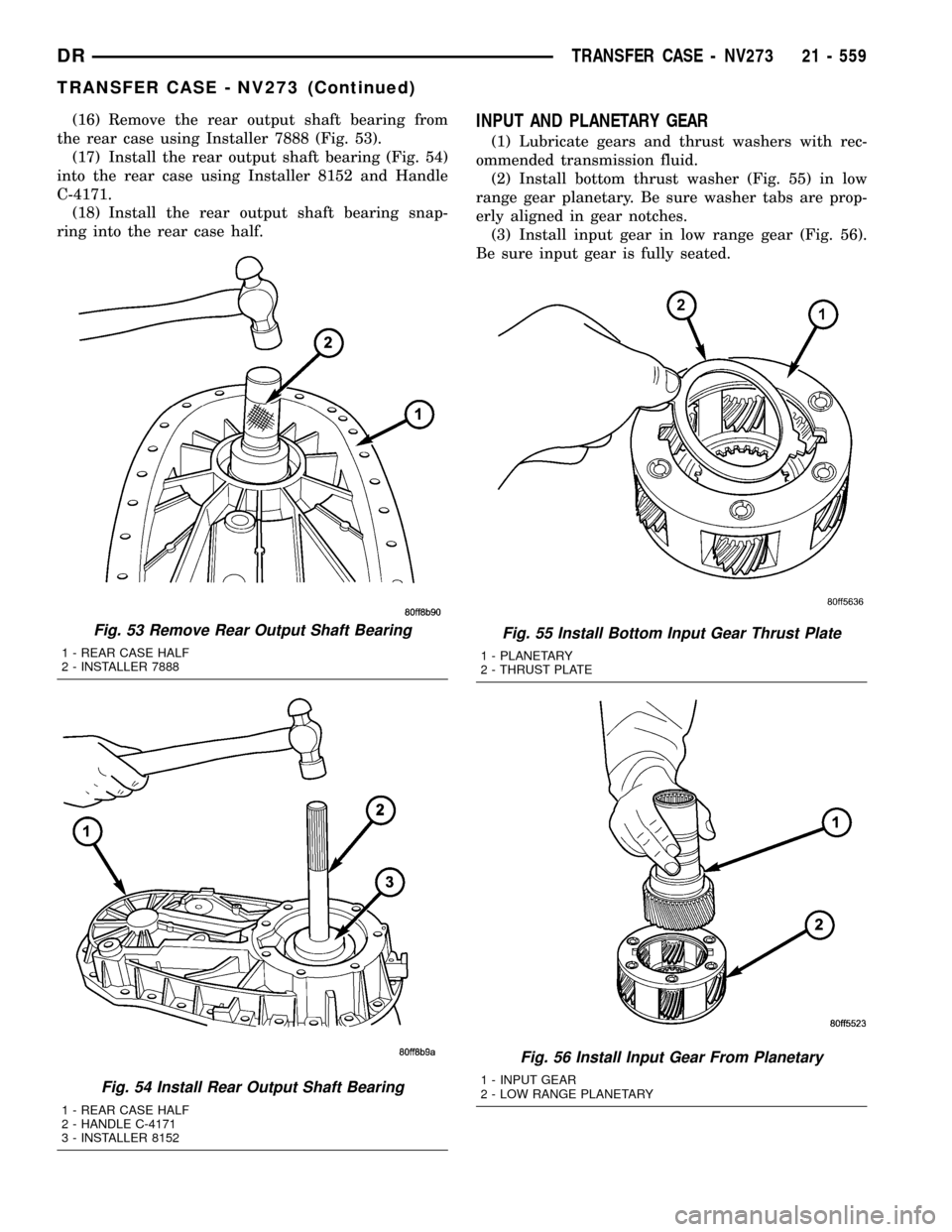
(16) Remove the rear output shaft bearing from
the rear case using Installer 7888 (Fig. 53).
(17) Install the rear output shaft bearing (Fig. 54)
into the rear case using Installer 8152 and Handle
C-4171.
(18) Install the rear output shaft bearing snap-
ring into the rear case half.INPUT AND PLANETARY GEAR
(1) Lubricate gears and thrust washers with rec-
ommended transmission fluid.
(2) Install bottom thrust washer (Fig. 55) in low
range gear planetary. Be sure washer tabs are prop-
erly aligned in gear notches.
(3) Install input gear in low range gear (Fig. 56).
Be sure input gear is fully seated.
Fig. 53 Remove Rear Output Shaft Bearing
1 - REAR CASE HALF
2 - INSTALLER 7888
Fig. 54 Install Rear Output Shaft Bearing
1 - REAR CASE HALF
2 - HANDLE C-4171
3 - INSTALLER 8152
Fig. 55 Install Bottom Input Gear Thrust Plate
1 - PLANETARY
2 - THRUST PLATE
Fig. 56 Install Input Gear From Planetary
1 - INPUT GEAR
2 - LOW RANGE PLANETARY
DRTRANSFER CASE - NV273 21 - 559
TRANSFER CASE - NV273 (Continued)
Page 2268 of 2627
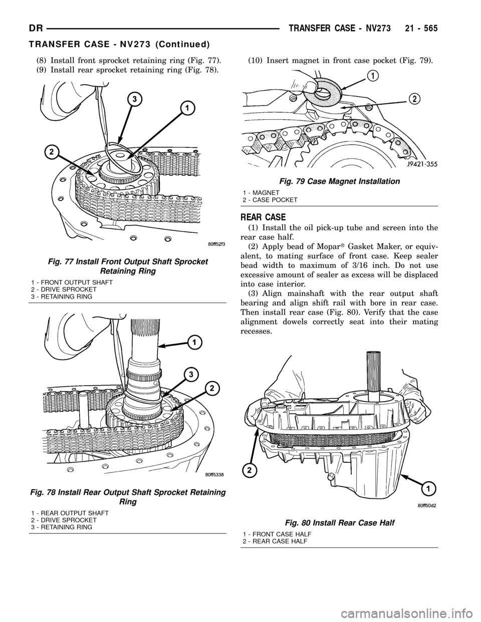
(8) Install front sprocket retaining ring (Fig. 77).
(9) Install rear sprocket retaining ring (Fig. 78).(10) Insert magnet in front case pocket (Fig. 79).
REAR CASE
(1) Install the oil pick-up tube and screen into the
rear case half.
(2) Apply bead of MopartGasket Maker, or equiv-
alent, to mating surface of front case. Keep sealer
bead width to maximum of 3/16 inch. Do not use
excessive amount of sealer as excess will be displaced
into case interior.
(3) Align mainshaft with the rear output shaft
bearing and align shift rail with bore in rear case.
Then install rear case (Fig. 80). Verify that the case
alignment dowels correctly seat into their mating
recesses.
Fig. 77 Install Front Output Shaft Sprocket
Retaining Ring
1 - FRONT OUTPUT SHAFT
2 - DRIVE SPROCKET
3 - RETAINING RING
Fig. 78 Install Rear Output Shaft Sprocket Retaining
Ring
1 - REAR OUTPUT SHAFT
2 - DRIVE SPROCKET
3 - RETAINING RING
Fig. 79 Case Magnet Installation
1 - MAGNET
2 - CASE POCKET
Fig. 80 Install Rear Case Half
1 - FRONT CASE HALF
2 - REAR CASE HALF
DRTRANSFER CASE - NV273 21 - 565
TRANSFER CASE - NV273 (Continued)
Page 2269 of 2627
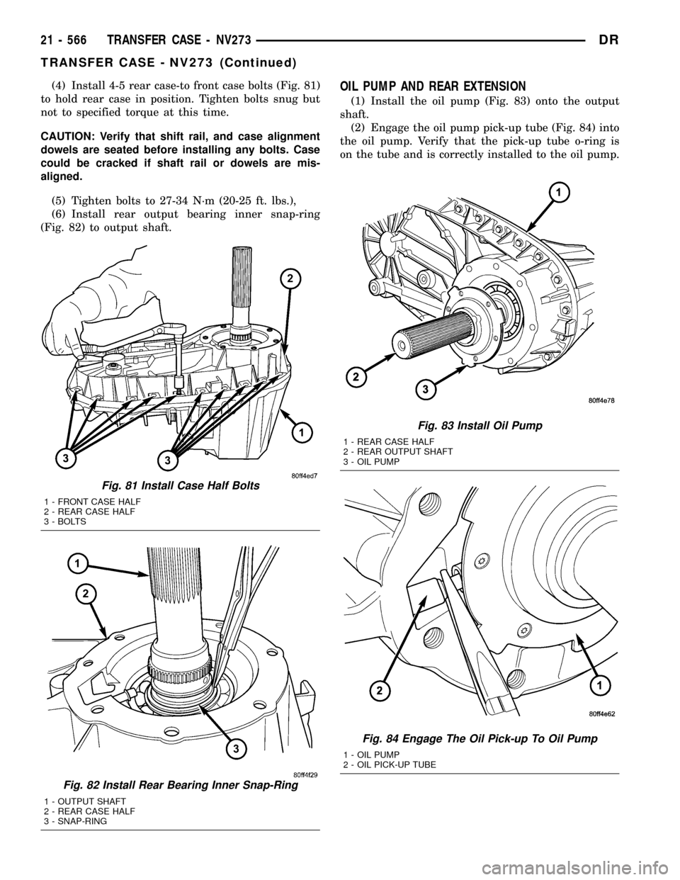
(4) Install 4-5 rear case-to front case bolts (Fig. 81)
to hold rear case in position. Tighten bolts snug but
not to specified torque at this time.
CAUTION: Verify that shift rail, and case alignment
dowels are seated before installing any bolts. Case
could be cracked if shaft rail or dowels are mis-
aligned.
(5) Tighten bolts to 27-34 N´m (20-25 ft. lbs.),
(6) Install rear output bearing inner snap-ring
(Fig. 82) to output shaft.OIL PUMP AND REAR EXTENSION
(1) Install the oil pump (Fig. 83) onto the output
shaft.
(2) Engage the oil pump pick-up tube (Fig. 84) into
the oil pump. Verify that the pick-up tube o-ring is
on the tube and is correctly installed to the oil pump.
Fig. 81 Install Case Half Bolts
1 - FRONT CASE HALF
2 - REAR CASE HALF
3 - BOLTS
Fig. 82 Install Rear Bearing Inner Snap-Ring
1 - OUTPUT SHAFT
2 - REAR CASE HALF
3 - SNAP-RING
Fig. 83 Install Oil Pump
1 - REAR CASE HALF
2 - REAR OUTPUT SHAFT
3 - OIL PUMP
Fig. 84 Engage The Oil Pick-up To Oil Pump
1 - OIL PUMP
2 - OIL PICK-UP TUBE
21 - 566 TRANSFER CASE - NV273DR
TRANSFER CASE - NV273 (Continued)
Page 2293 of 2627
STUDS
REMOVAL
(1) Raise and support the vehicle.
(2) Remove the wheel and tire assembly.
(3) Remove the brake caliper, caliper adapter and
rotor, (Refer to 5 - BRAKES/HYDRAULIC/MECHAN-
ICAL/ROTORS - REMOVAL).
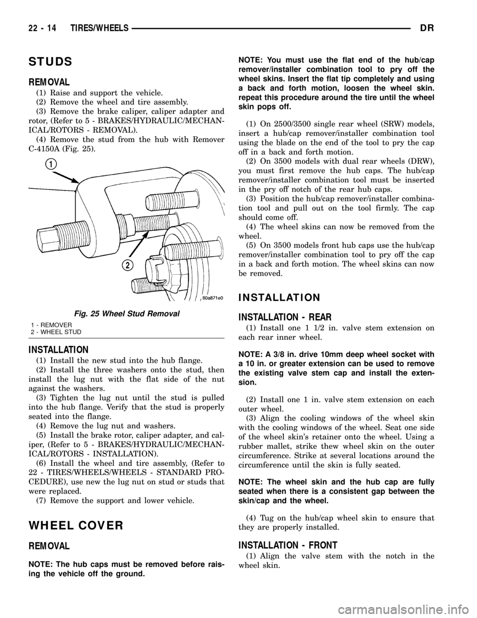
(4) Remove the stud from the hub with Remover
C-4150A (Fig. 25).
INSTALLATION
(1) Install the new stud into the hub flange.
(2) Install the three washers onto the stud, then
install the lug nut with the flat side of the nut
against the washers.
(3) Tighten the lug nut until the stud is pulled
into the hub flange. Verify that the stud is properly
seated into the flange.
(4) Remove the lug nut and washers.
(5) Install the brake rotor, caliper adapter, and cal-
iper, (Refer to 5 - BRAKES/HYDRAULIC/MECHAN-
ICAL/ROTORS - INSTALLATION).
(6) Install the wheel and tire assembly, (Refer to
22 - TIRES/WHEELS/WHEELS - STANDARD PRO-
CEDURE), use new the lug nut on stud or studs that
were replaced.
(7) Remove the support and lower vehicle.
WHEEL COVER
REMOVAL
NOTE: The hub caps must be removed before rais-
ing the vehicle off the ground.NOTE: You must use the flat end of the hub/cap
remover/installer combination tool to pry off the
wheel skins. Insert the flat tip completely and using
a back and forth motion, loosen the wheel skin.
repeat this procedure around the tire until the wheel
skin pops off.
(1) On 2500/3500 single rear wheel (SRW) models,
insert a hub/cap remover/installer combination tool
using the blade on the end of the tool to pry the cap
off in a back and forth motion.
(2) On 3500 models with dual rear wheels (DRW),
you must first remove the hub caps. The hub/cap
remover/installer combination tool must be inserted
in the pry off notch of the rear hub caps.
(3) Position the hub/cap remover/installer combina-
tion tool and pull out on the tool firmly. The cap
should come off.
(4) The wheel skins can now be removed from the
wheel.
(5) On 3500 models front hub caps use the hub/cap
remover/installer combination tool to pry off the cap
in a back and forth motion. The wheel skins can now
be removed.
INSTALLATION
INSTALLATION - REAR
(1) Install one 1 1/2 in. valve stem extension on
each rear inner wheel.
NOTE: A 3/8 in. drive 10mm deep wheel socket with
a 10 in. or greater extension can be used to remove
the existing valve stem cap and install the exten-
sion.
(2) Install one 1 in. valve stem extension on each
outer wheel.
(3) Align the cooling windows of the wheel skin
with the cooling windows of the wheel. Seat one side
of the wheel skin's retainer onto the wheel. Using a
rubber mallet, strike thew wheel skin on the outer
circumference. Strike at several locations around the
circumference until the skin is fully seated.
NOTE: The wheel skin and the hub cap are fully
seated when there is a consistent gap between the
skin/cap and the wheel.
(4) Tug on the hub/cap wheel skin to ensure that
they are properly installed.
INSTALLATION - FRONT
(1) Align the valve stem with the notch in the
wheel skin.
Fig. 25 Wheel Stud Removal
1 - REMOVER
2 - WHEEL STUD
22 - 14 TIRES/WHEELSDR
Page 2296 of 2627
BODY
TABLE OF CONTENTS
page page
BODY
WARNING
SAFETY PRECAUTIONS AND WARNINGS . . . 1
DIAGNOSIS AND TESTING
DIAGNOSIS AND TESTING - WATER LEAKS . 1
DIAGNOSIS AND TESTING - WIND NOISE . . . 2
STANDARD PROCEDURE
STANDARD PROCEDURE - BODY
LUBRICATION.........................3
STANDARD PROCEDURE - HEAT STAKING . . 3
STANDARD PROCEDURE - PLASTIC BODY
PANEL REPAIR........................3
STANDARD PROCEDURE - BUZZ, SQUEAK
& RATTLE...........................11
SPECIFICATIONS - TORQUE..............12SPECIAL TOOLS
BODY..............................14
TAILGATE..............................15
DOOR - FRONT.........................18
DOORS - REAR.........................28
EXTERIOR.............................36
HOOD.................................46
INSTRUMENT PANEL.....................49
INTERIOR..............................62
PAINT.................................73
SEATS................................75
STATIONARY GLASS.....................86
WEATHERSTRIP/SEALS...................91
BODY STRUCTURE......................95
BODY
WARNING
SAFETY PRECAUTIONS AND WARNINGS
WARNING: USE AN OSHA APPROVED BREATHING
FILTER WHEN SPRAYING PAINT OR SOLVENTS IN
A CONFINED AREA. PERSONAL INJURY CAN
RESULT.
²AVOID PROLONGED SKIN CONTACT WITH
PETROLEUM OR ALCOHOL ± BASED CLEANING
SOLVENTS. PERSONAL INJURY CAN RESULT.
²DO NOT STAND UNDER A HOISTED VEHICLE
THAT IS NOT PROPERLY SUPPORTED ON SAFETY
STANDS. PERSONAL INJURY CAN RESULT.
CAUTION: When holes must be drilled or punched
in an inner body panel, verify depth of space to the
outer body panel, electrical wiring, or other compo-
nents. Damage to vehicle can result.
²Do not weld exterior panels unless combustible
material on the interior of vehicle is removed from
the repair area. Fire or hazardous conditions, can
result.
²Always have a fire extinguisher ready for use
when welding.
²Disconnect the negative (-) cable clamp from
the battery when servicing electrical components
that are live when the ignition is OFF. Damage to
electrical system can result.²Do not use abrasive chemicals or compounds
on painted surfaces. Damage to finish can result.
²Do not use harsh alkaline based cleaning sol-
vents on painted or upholstered surfaces. Damage
to finish or color can result.
²Do not hammer or pound on plastic trim panel
when servicing interior trim. Plastic panels can
break.
DIAGNOSIS AND TESTING
DIAGNOSIS AND TESTING - WATER LEAKS
Water leaks can be caused by poor sealing,
improper body component alignment, body seam
porosity, missing plugs, or blocked drain holes. Cen-
trifugal and gravitational force can cause water to
drip from a location away from the actual leak point,
making leak detection difficult. All body sealing
points should be water tight in normal wet-driving
conditions. Water flowing downward from the front of
the vehicle should not enter the passenger or luggage
compartment. Moving sealing surfaces will not
always seal water tight under all conditions. At
times, side glass or door seals will allow water to
enter the passenger compartment during high pres-
sure washing or hard driving rain (severe) condi-
tions. Overcompensating on door or glass
adjustments to stop a water leak that occurs under
severe conditions can cause premature seal wear and
excessive closing or latching effort. After completing
a repair, water test vehicle to verify leak has stopped
before returning vehicle to use.
DRBODY 23 - 1