1998 DODGE RAM 1500 fuel tank removal
[x] Cancel search: fuel tank removalPage 1632 of 2627
FUEL TANK MODULE
DESCRIPTION
An electric fuel pump isnot usedin the fuel tank
module for diesel powered engines. Fuel is supplied
by the engine mounted fuel transfer (lift) pump.
The fuel tank module is installed in the top of the
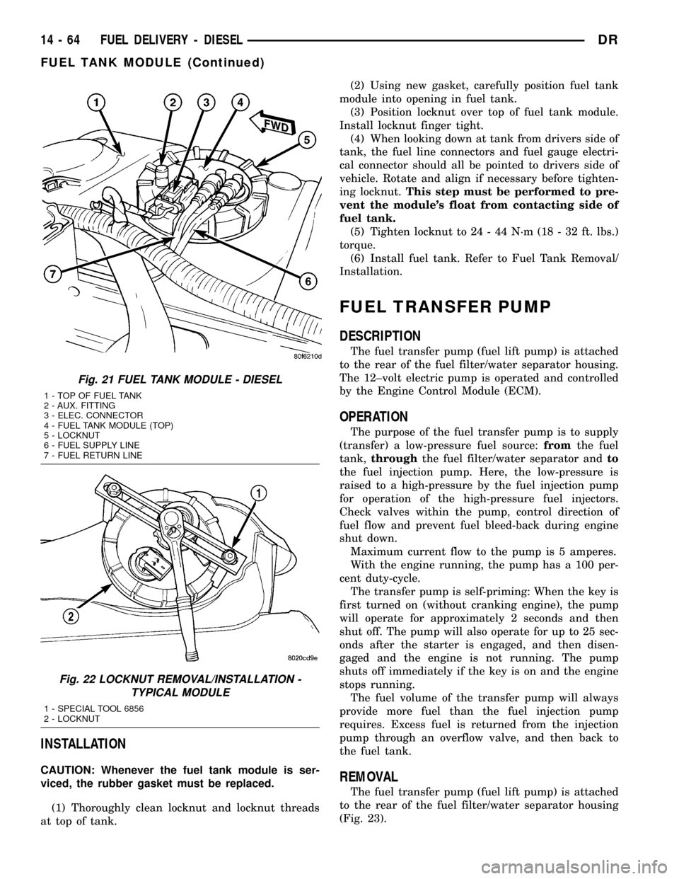
fuel tank (Fig. 21). The fuel tank module contains
the following components:
²Fuel reservoir
²A separate in-tank fuel filter
²Fuel gauge sending unit (fuel level sensor)
²Fuel supply line connection
²Fuel return line connection
²Auxiliary non-pressurized fitting
OPERATION
Refer to Fuel Gauge Sending Unit.
REMOVAL
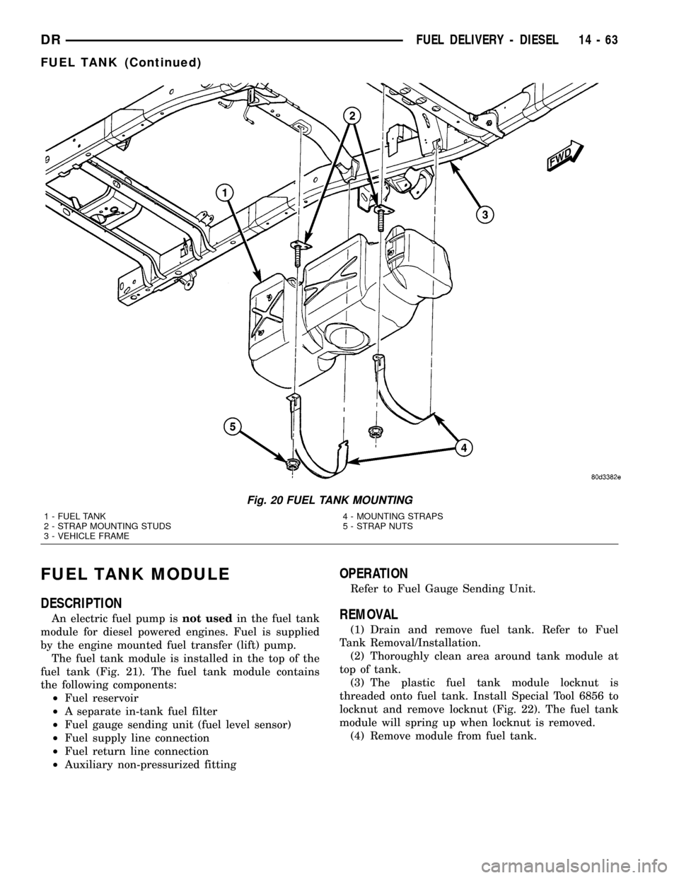
(1) Drain and remove fuel tank. Refer to Fuel
Tank Removal/Installation.
(2) Thoroughly clean area around tank module at
top of tank.
(3) The plastic fuel tank module locknut is
threaded onto fuel tank. Install Special Tool 6856 to
locknut and remove locknut (Fig. 22). The fuel tank
module will spring up when locknut is removed.
(4) Remove module from fuel tank.
Fig. 20 FUEL TANK MOUNTING
1 - FUEL TANK
2 - STRAP MOUNTING STUDS
3 - VEHICLE FRAME4 - MOUNTING STRAPS
5 - STRAP NUTS
DRFUEL DELIVERY - DIESEL 14 - 63
FUEL TANK (Continued)
Page 1633 of 2627
INSTALLATION
CAUTION: Whenever the fuel tank module is ser-
viced, the rubber gasket must be replaced.
(1) Thoroughly clean locknut and locknut threads
at top of tank.(2) Using new gasket, carefully position fuel tank
module into opening in fuel tank.
(3) Position locknut over top of fuel tank module.
Install locknut finger tight.
(4) When looking down at tank from drivers side of
tank, the fuel line connectors and fuel gauge electri-
cal connector should all be pointed to drivers side of
vehicle. Rotate and align if necessary before tighten-
ing locknut.This step must be performed to pre-
vent the module's float from contacting side of
fuel tank.
(5) Tighten locknut to 24 - 44 N´m (18 - 32 ft. lbs.)
torque.
(6) Install fuel tank. Refer to Fuel Tank Removal/
Installation.
FUEL TRANSFER PUMP
DESCRIPTION
The fuel transfer pump (fuel lift pump) is attached
to the rear of the fuel filter/water separator housing.
The 12±volt electric pump is operated and controlled
by the Engine Control Module (ECM).
OPERATION
The purpose of the fuel transfer pump is to supply
(transfer) a low-pressure fuel source:fromthe fuel
tank,throughthe fuel filter/water separator andto
the fuel injection pump. Here, the low-pressure is
raised to a high-pressure by the fuel injection pump
for operation of the high-pressure fuel injectors.
Check valves within the pump, control direction of
fuel flow and prevent fuel bleed-back during engine
shut down.
Maximum current flow to the pump is 5 amperes.
With the engine running, the pump has a 100 per-
cent duty-cycle.
The transfer pump is self-priming: When the key is
first turned on (without cranking engine), the pump
will operate for approximately 2 seconds and then
shut off. The pump will also operate for up to 25 sec-
onds after the starter is engaged, and then disen-
gaged and the engine is not running. The pump
shuts off immediately if the key is on and the engine
stops running.
The fuel volume of the transfer pump will always
provide more fuel than the fuel injection pump
requires. Excess fuel is returned from the injection
pump through an overflow valve, and then back to
the fuel tank.
REMOVAL
The fuel transfer pump (fuel lift pump) is attached
to the rear of the fuel filter/water separator housing
(Fig. 23).
Fig. 21 FUEL TANK MODULE - DIESEL
1 - TOP OF FUEL TANK
2 - AUX. FITTING
3 - ELEC. CONNECTOR
4 - FUEL TANK MODULE (TOP)
5 - LOCKNUT
6 - FUEL SUPPLY LINE
7 - FUEL RETURN LINE
Fig. 22 LOCKNUT REMOVAL/INSTALLATION -
TYPICAL MODULE
1 - SPECIAL TOOL 6856
2 - LOCKNUT
14 - 64 FUEL DELIVERY - DIESELDR
FUEL TANK MODULE (Continued)
Page 1634 of 2627
(1) Drain fuel from fuel filter housing. Refer to
Fuel Filter/Water Separator - Removal. See Draining.
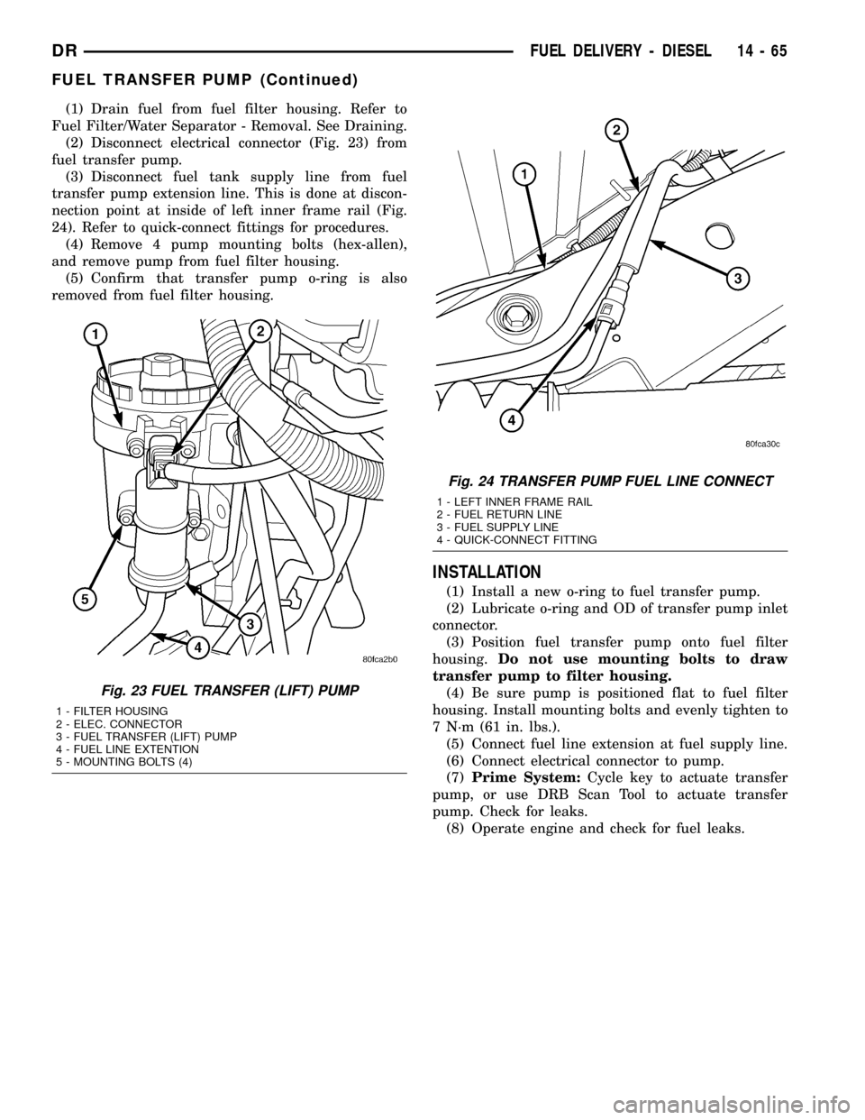
(2) Disconnect electrical connector (Fig. 23) from
fuel transfer pump.
(3) Disconnect fuel tank supply line from fuel
transfer pump extension line. This is done at discon-
nection point at inside of left inner frame rail (Fig.
24). Refer to quick-connect fittings for procedures.
(4) Remove 4 pump mounting bolts (hex-allen),
and remove pump from fuel filter housing.
(5) Confirm that transfer pump o-ring is also
removed from fuel filter housing.
INSTALLATION
(1) Install a new o-ring to fuel transfer pump.
(2) Lubricate o-ring and OD of transfer pump inlet
connector.
(3) Position fuel transfer pump onto fuel filter
housing.Do not use mounting bolts to draw
transfer pump to filter housing.
(4) Be sure pump is positioned flat to fuel filter
housing. Install mounting bolts and evenly tighten to
7 N´m (61 in. lbs.).
(5) Connect fuel line extension at fuel supply line.
(6) Connect electrical connector to pump.
(7)Prime System:Cycle key to actuate transfer
pump, or use DRB Scan Tool to actuate transfer
pump. Check for leaks.
(8) Operate engine and check for fuel leaks.
Fig. 23 FUEL TRANSFER (LIFT) PUMP
1 - FILTER HOUSING
2 - ELEC. CONNECTOR
3 - FUEL TRANSFER (LIFT) PUMP
4 - FUEL LINE EXTENTION
5 - MOUNTING BOLTS (4)
Fig. 24 TRANSFER PUMP FUEL LINE CONNECT
1 - LEFT INNER FRAME RAIL
2 - FUEL RETURN LINE
3 - FUEL SUPPLY LINE
4 - QUICK-CONNECT FITTING
DRFUEL DELIVERY - DIESEL 14 - 65
FUEL TRANSFER PUMP (Continued)
Page 1635 of 2627
CASCADE OVERFLOW VALVE
DESCRIPTION
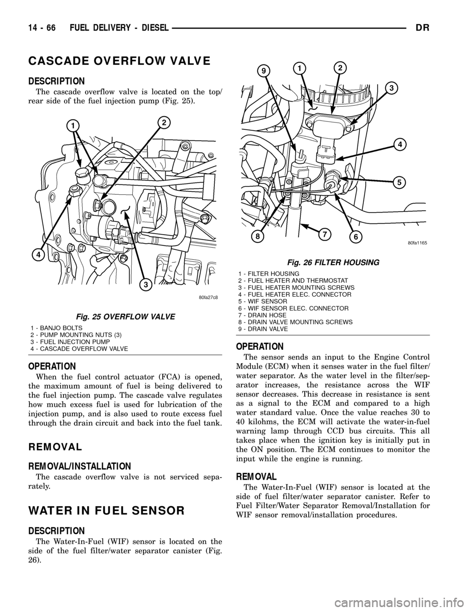
The cascade overflow valve is located on the top/
rear side of the fuel injection pump (Fig. 25).
OPERATION
When the fuel control actuator (FCA) is opened,
the maximum amount of fuel is being delivered to
the fuel injection pump. The cascade valve regulates
how much excess fuel is used for lubrication of the
injection pump, and is also used to route excess fuel
through the drain circuit and back into the fuel tank.
REMOVAL
REMOVAL/INSTALLATION
The cascade overflow valve is not serviced sepa-
rately.
WATER IN FUEL SENSOR
DESCRIPTION
The Water-In-Fuel (WIF) sensor is located on the
side of the fuel filter/water separator canister (Fig.
26).
OPERATION
The sensor sends an input to the Engine Control
Module (ECM) when it senses water in the fuel filter/
water separator. As the water level in the filter/sep-
arator increases, the resistance across the WIF
sensor decreases. This decrease in resistance is sent
as a signal to the ECM and compared to a high
water standard value. Once the value reaches 30 to
40 kilohms, the ECM will activate the water-in-fuel
warning lamp through CCD bus circuits. This all
takes place when the ignition key is initially put in
the ON position. The ECM continues to monitor the
input while the engine is running.
REMOVAL
The Water-In-Fuel (WIF) sensor is located at the
side of fuel filter/water separator canister. Refer to
Fuel Filter/Water Separator Removal/Installation for
WIF sensor removal/installation procedures.
Fig. 25 OVERFLOW VALVE
1 - BANJO BOLTS
2 - PUMP MOUNTING NUTS (3)
3 - FUEL INJECTION PUMP
4 - CASCADE OVERFLOW VALVE
Fig. 26 FILTER HOUSING
1 - FILTER HOUSING
2 - FUEL HEATER AND THERMOSTAT
3 - FUEL HEATER MOUNTING SCREWS
4 - FUEL HEATER ELEC. CONNECTOR
5 - WIF SENSOR
6 - WIF SENSOR ELEC. CONNECTOR
7 - DRAIN HOSE
8 - DRAIN VALVE MOUNTING SCREWS
9 - DRAIN VALVE
14 - 66 FUEL DELIVERY - DIESELDR
Page 1643 of 2627
FUEL CONTROL ACTUATOR
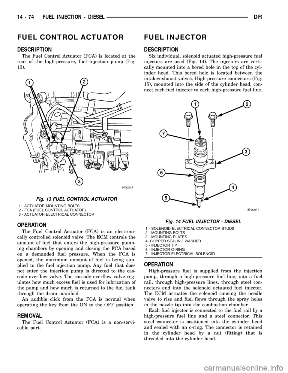
DESCRIPTION
The Fuel Control Actuator (FCA) is located at the
rear of the high-pressure, fuel injection pump (Fig.
13).
OPERATION
The Fuel Control Actuator (FCA) is an electroni-
cally controlled solenoid valve. The ECM controls the
amount of fuel that enters the high-pressure pump-
ing chambers by opening and closing the FCA based
on a demanded fuel pressure. When the FCA is
opened, the maximum amount of fuel is being sup-
plied to the fuel injection pump. Any fuel that does
not enter the injection pump is directed to the cas-
cade overflow valve. The cascade overflow valve reg-
ulates how much excess fuel is used for lubrication of
the pump and how much is returned to the fuel tank
through the drain manifold.
An audible click from the FCA is normal when
operating the key from the ON to the OFF position.
REMOVAL
The Fuel Control Actuator (FCA) is a non-servi-
cable part.
FUEL INJECTOR
DESCRIPTION
Six individual, solenoid actuated high-pressure fuel
injectors are used (Fig. 14). The injectors are verti-
cally mounted into a bored hole in the top of the cyl-
inder head. This bored hole is located between the
intake/exhaust valves. High-pressure connectors (Fig.
15), mounted into the side of the cylinder head, con-
nect each fuel injector to each high-pressure fuel line.
OPERATION
High-pressure fuel is supplied from the injection
pump, through a high-pressure fuel line, into a fuel
rail, through high-pressure lines, through steel con-
nectors and into the solenoid actuated fuel injector.
The ECM actuates the solenoid causing the needle
valve to rise and fuel flows through the spray holes
in the nozzle tip into the combustion chamber.
Each fuel injector is connected to the fuel rail by a
high-pressure fuel line and a steel connector. This
steel connector is positioned into the cylinder head
and sealed with an o-ring. The connector is retained
in the cylinder head by a nut (fitting) that is
threaded into the cylinder head.
Fig. 13 FUEL CONTROL ACTUATOR
1 - ACTUATOR MOUNTING BOLTS
2 - FCA (FUEL CONTROL ACTUATOR)
3 - ACTUATOR ELECTRICAL CONNECTOR
Fig. 14 FUEL INJECTOR - DIESEL
1 - SOLENOID ELECTRICAL CONNECTOR STUDS
2 - MOUNTING BOLTS
3 - MOUNTING PLATES
4- COPPER SEALING WASHER
5 - INJECTOR TIP
6 - INJECTOR O-RING
7 - INJECTOR ELECTRICAL SOLENOID
14 - 74 FUEL INJECTION - DIESELDR
Page 2332 of 2627
INSTALLATION
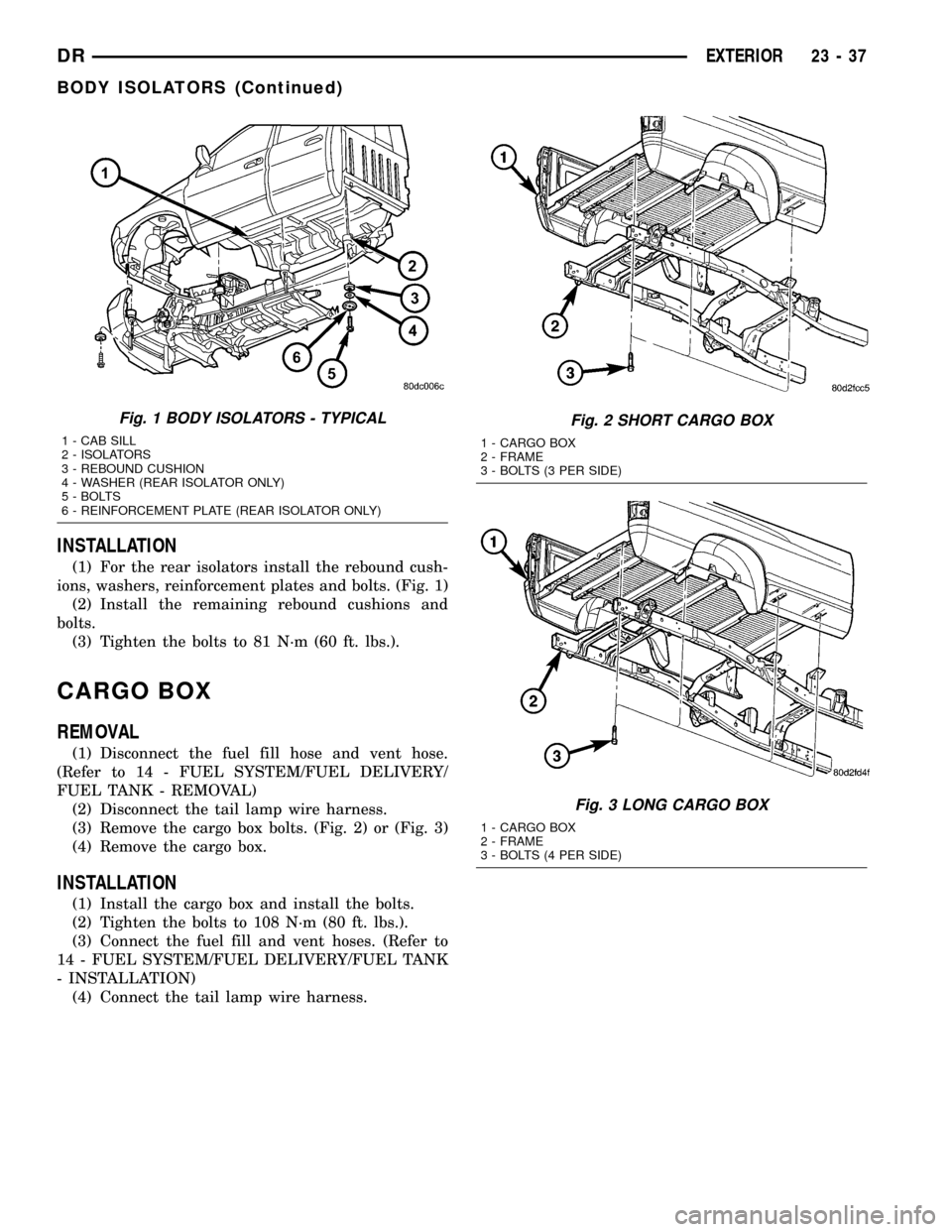
(1) For the rear isolators install the rebound cush-
ions, washers, reinforcement plates and bolts. (Fig. 1)
(2) Install the remaining rebound cushions and
bolts.
(3) Tighten the bolts to 81 N´m (60 ft. lbs.).
CARGO BOX
REMOVAL
(1) Disconnect the fuel fill hose and vent hose.
(Refer to 14 - FUEL SYSTEM/FUEL DELIVERY/
FUEL TANK - REMOVAL)
(2) Disconnect the tail lamp wire harness.
(3) Remove the cargo box bolts. (Fig. 2) or (Fig. 3)
(4) Remove the cargo box.
INSTALLATION
(1) Install the cargo box and install the bolts.
(2) Tighten the bolts to 108 N´m (80 ft. lbs.).
(3) Connect the fuel fill and vent hoses. (Refer to
14 - FUEL SYSTEM/FUEL DELIVERY/FUEL TANK
- INSTALLATION)
(4) Connect the tail lamp wire harness.
Fig. 1 BODY ISOLATORS - TYPICAL
1 - CAB SILL
2 - ISOLATORS
3 - REBOUND CUSHION
4 - WASHER (REAR ISOLATOR ONLY)
5 - BOLTS
6 - REINFORCEMENT PLATE (REAR ISOLATOR ONLY)
Fig. 2 SHORT CARGO BOX
1 - CARGO BOX
2 - FRAME
3 - BOLTS (3 PER SIDE)
Fig. 3 LONG CARGO BOX
1 - CARGO BOX
2 - FRAME
3 - BOLTS (4 PER SIDE)
DREXTERIOR 23 - 37
BODY ISOLATORS (Continued)
Page 2571 of 2627

EVAPORATIVE EMISSIONS
TABLE OF CONTENTS
page page
EVAPORATIVE EMISSIONS
DESCRIPTION - EVAP SYSTEM............10
SPECIFICATIONS
TORQUE - EVAP SYSTEM...............11
CCV HOSE
DESCRIPTION - 8.0L V-10................12
OPERATION - 8.0L V-10..................12
EVAP/PURGE SOLENOID
DESCRIPTION.........................12
OPERATION...........................12
REMOVAL.............................12
INSTALLATION.........................12
FUEL FILLER CAP
DESCRIPTION.........................13
OPERATION...........................13
REMOVAL
REMOVAL/INSTALLATION...............13
LEAK DETECTION PUMP
DESCRIPTION.........................13
OPERATION...........................14
REMOVAL.............................16
INSTALLATION.........................16ORVR
DESCRIPTION.........................17
OPERATION...........................17
P C V VA LV E
DESCRIPTION.........................17
OPERATION...........................19
DIAGNOSIS AND TESTING - PCV VALVE -
3.7L V-6/ 4.7L V-8......................20
REMOVAL.............................21
INSTALLATION.........................21
VACUUM LINES
DESCRIPTION.........................22
VAPOR CANISTER
DESCRIPTION.........................22
OPERATION...........................22
REMOVAL.............................22
INSTALLATION.........................22
NATURAL VAC LEAK DETECTION ASSY
DESCRIPTION.........................23
OPERATION...........................23
REMOVAL.............................24
INSTALLATION.........................25
EVAPORATIVE EMISSIONS
DESCRIPTION - EVAP SYSTEM
The evaporation control system prevents the emis-
sion of fuel tank vapors into the atmosphere. When
fuel evaporates in the fuel tank, the vapors pass
through vent hoses or tubes into the two charcoal
filled evaporative canisters. The canisters tempo-
rarily hold the vapors. The Powertrain Control Mod-
ule (PCM) allows intake manifold vacuum to draw
vapors into the combustion chambers during certain
operating conditions.
All gasoline powered engines use a duty cycle
purge system. The PCM controls vapor flow by oper-
ating the duty cycle EVAP purge solenoid. Refer to
Duty Cycle EVAP Canister Purge Solenoid for addi-
tional information.When equipped with certain emissions packages, a
Leak Detection Pump (LDP) will be used as part of
the evaporative system. This pump is used as a part
of OBD II requirements. Refer to Leak Detection
Pump for additional information. Other emissions
packages will use a Natural Vacuum Leak Detection
(NVLD) system in place of the LDP. Refer to NVLD
for additional information.
NOTE: The hoses used in this system are specially
manufactured. If replacement becomes necessary, it
is important to use only fuel resistant hose.
Certain EVAP system components can be found in
(Fig. 1).
25 - 10 EVAPORATIVE EMISSIONSDR
Page 2574 of 2627
FUEL FILLER CAP
DESCRIPTION
The plastic fuel tank filler tube cap is threaded
onto the end of the fuel fill tube. Certain models are
equipped with a 1/4 turn cap.
OPERATION
The loss of any fuel or vapor out of fuel filler tube
is prevented by the use of a pressure-vacuum fuel fill
cap. Relief valves inside the cap will release fuel tank
pressure at predetermined pressures. Fuel tank vac-
uum will also be released at predetermined values.
This cap must be replaced by a similar unit if
replacement is necessary. This is in order for the sys-
tem to remain effective.
CAUTION: Remove fill cap before servicing any fuel
system component to relieve tank pressure. If
equipped with a Leak Detection Pump (LDP), or
NVLD system, the cap must be tightened securely.
If cap is left loose, a Diagnostic Trouble Code (DTC)
may be set.
REMOVAL
REMOVAL/INSTALLATION
If replacement of the 1/4 turn fuel tank filler tube
cap is necessary, it must be replaced with an identi-
cal cap to be sure of correct system operation.
CAUTION: Remove the fuel tank filler tube cap to
relieve fuel tank pressure. The cap must be
removed prior to disconnecting any fuel system
component or before draining the fuel tank.
LEAK DETECTION PUMP
DESCRIPTION
Vehicles equipped with JTEC engine control mod-
ules use a leak detection pump. Vehicles equipped
with NGC engine control modules use an NVLD
pump. Refer to Natural Vacuum - Leak Detection
(NVLD) for additional information.
The evaporative emission system is designed to
prevent the escape of fuel vapors from the fuel sys-
tem (Fig. 4). Leaks in the system, even small ones,
can allow fuel vapors to escape into the atmosphere.
Government regulations require onboard testing to
make sure that the evaporative (EVAP) system is
functioning properly. The leak detection system tests
for EVAP system leaks and blockage. It also performs
self-diagnostics. During self-diagnostics, the Power-
train Control Module (PCM) first checks the Leak
Detection Pump (LDP) for electrical and mechanical
faults. If the first checks pass, the PCM then uses
the LDP to seal the vent valve and pump air into the
system to pressurize it. If a leak is present, the PCM
will continue pumping the LDP to replace the air
that leaks out. The PCM determines the size of the
leak based on how fast/long it must pump the LDP
as it tries to maintain pressure in the system.
EVAP LEAK DETECTION SYSTEM COMPONENTS
Service Port: Used with special tools like the Miller
Evaporative Emissions Leak Detector (EELD) to test
for leaks in the system.
EVAP Purge Solenoid: The PCM uses the EVAP
purge solenoid to control purging of excess fuel
vapors stored in the EVAP canister. It remains closed
during leak testing to prevent loss of pressure.
EVAP Canister: The EVAP canister stores fuel
vapors from the fuel tank for purging.
EVAP Purge Orifice: Limits purge volume.
EVAP System Air Filter: Provides air to the LDP
for pressurizing the system. It filters out dirt while
allowing a vent to atmosphere for the EVAP system.
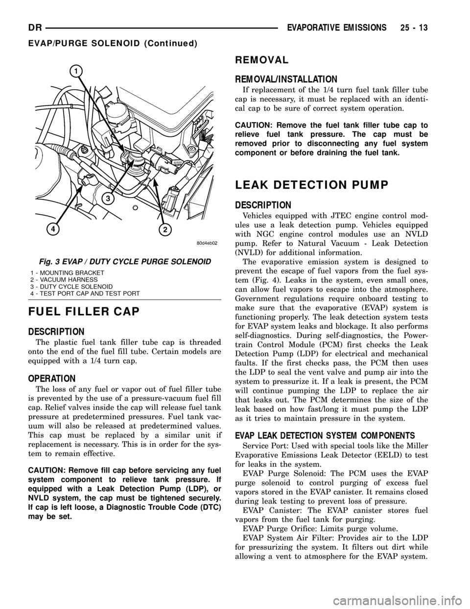
Fig. 3 EVAP / DUTY CYCLE PURGE SOLENOID
1 - MOUNTING BRACKET
2 - VACUUM HARNESS
3 - DUTY CYCLE SOLENOID
4 - TEST PORT CAP AND TEST PORT
DREVAPORATIVE EMISSIONS 25 - 13
EVAP/PURGE SOLENOID (Continued)