1998 DODGE RAM 1500 front end lighting
[x] Cancel search: front end lightingPage 992 of 2627

8W-51 REAR LIGHTING
Component Page
Backup Lamp Switch............... 8W-51-3, 5
Brake Lamp Switch.................. 8W-51-7
Center High Mounted Stop Lamp-
Aftermarket...................... 8W-51-7
Center High Mounted Stop Lamp/Cargo
Lamp........................... 8W-51-7
Fender Lamp-Front Left............... 8W-51-4
Fender Lamp-Front Right............. 8W-51-4
Fender Lamp-Rear Left............... 8W-51-4
Fender Lamp-Rear Right.............. 8W-51-4
Front Control Module......... 8W-51-2, 3, 5, 6, 7
Fuse 15........................ 8W-51-2, 3, 7
Fuse 24............................ 8W-51-7
Fuse 32............................ 8W-51-3
Fuse 33............................ 8W-51-7
Fuse 34............................ 8W-51-2
Fuse 38............................ 8W-51-3Component Page
G104........................ 8W-51-2, 4, 5, 6
G202.............................. 8W-51-7
Integrated Power Module...... 8W-51-2, 3, 5, 6, 7
License Lamp-Left................... 8W-51-2
License Lamp-Right.................. 8W-51-2
Park Lamp Relay................ 8W-51-2, 3, 7
Park/Turn Signal Lamp-Left Front....... 8W-51-2
Park/Turn Signal Lamp-Right Front..... 8W-51-3
Tail/Stop/Turn Signal Lamp-Left...... 8W-51-2, 5
Tail/Stop/Turn Signal Lamp-Right....... 8W-51-6
Tailgate Lamp.................... 8W-51-2, 4
Trailer Tow Connector................ 8W-51-7
Trailer Tow Connector-Add On........ 8W-51-5, 7
Transmission Range Sensor............ 8W-51-5
Transmission Solenoid/TRS Assembly.... 8W-51-5
DR8W-51 REAR LIGHTING 8W - 51 - 1
Page 1554 of 2627
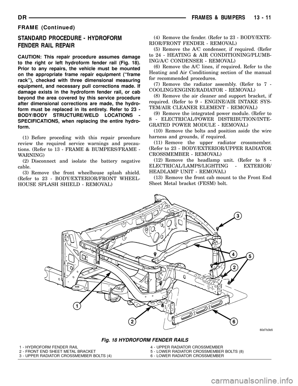
STANDARD PROCEDURE - HYDROFORM
FENDER RAIL REPAIR
CAUTION: This repair procedure assumes damage
to the right or left hydroform fender rail (Fig. 18).
Prior to any repairs, the vehicle must be mounted
on the appropriate frame repair equipment (ªframe
rackº), checked with three dimensional measuring
equipment, and necessary pull corrections made. If
damage exists in the hydroform fender rail, or cab
beyond the area covered by this service procedure
after dimensional corrections are made, the hydro-
form must be replaced in its entirety. Refer to 23 -
BODY/BODY STRUCTURE/WELD LOCATIONS -
SPECIFICATIONS, when replacing the entire hydro-
form.
(1) Before proceding with this repair procedure
review the required service warnings and precau-
tions. (Refer to 13 - FRAME & BUMPERS/FRAME -
WARNING)
(2) Disconnect and isolate the battery negative
cable.
(3) Remove the front wheelhouse splash shield.
(Refer to 23 - BODY/EXTERIOR/FRONT WHEEL-
HOUSE SPLASH SHIELD - REMOVAL)(4) Remove the fender. (Refer to 23 - BODY/EXTE-
RIOR/FRONT FENDER - REMOVAL)
(5) Remove the A/C condenser, if required. (Refer
to 24 - HEATING & AIR CONDITIONING/PLUMB-
ING/A/C CONDENSER - REMOVAL)
(6) Remove the A/C lines, if required. Refer to the
Heating and Air Conditioning section of the manual
for recommended procedures.
(7) Remove the radiator assembly. (Refer to 7 -
COOLING/ENGINE/RADIATOR - REMOVAL)
(8) Remove the air cleaner and support bracket, if
required. (Refer to 9 - ENGINE/AIR INTAKE SYS-
TEM/AIR CLEANER ELEMENT - REMOVAL)
(9) Remove the integrated power module. (Refer to
8 - ELECTRICAL/POWER DISTRIBUTION/INTE-
GRATED POWER MODULE - REMOVAL)
(10) Remove the bolts and position aside the wire
harness and grounds, if required.
(11) Remove the upper radiator crossmember.
(Refer to 23 - BODY/EXTERIOR/UPPER RADIATOR
CROSSMEMBER - REMOVAL)
(12) Remove the headlamp unit. (Refer to 8 -
ELECTRICAL/LAMPS/LIGHTING - EXTERIOR/
HEADLAMP UNIT - REMOVAL)
(13) Remove the front cab mount to the Front End
Sheet Metal bracket (FESM) bolt.
Fig. 18 HYDROFORM FENDER RAILS
1 - HYDROFORM FENDER RAIL
2 - FRONT END SHEET METAL BRACKET
3 - UPPER RADIATOR CROSSMEMBER BOLTS (4)4 - UPPER RADIATOR CROSSMEMBER
5 - LOWER RADIATOR CROSSMEMBER BOLTS (8)
6 - LOWER RADIATOR CROSSMEMBER
DRFRAMES & BUMPERS 13 - 11
FRAME (Continued)
Page 1555 of 2627
(14) Remove the bolts attaching the lower radiator
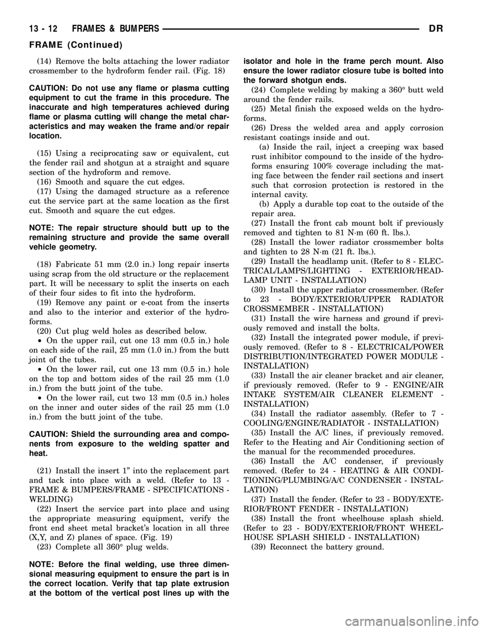
crossmember to the hydroform fender rail. (Fig. 18)
CAUTION: Do not use any flame or plasma cutting
equipment to cut the frame in this procedure. The
inaccurate and high temperatures achieved during
flame or plasma cutting will change the metal char-
acteristics and may weaken the frame and/or repair
location.
(15) Using a reciprocating saw or equivalent, cut
the fender rail and shotgun at a straight and square
section of the hydroform and remove.
(16) Smooth and square the cut edges.
(17) Using the damaged structure as a reference
cut the service part at the same location as the first
cut. Smooth and square the cut edges.
NOTE: The repair structure should butt up to the
remaining structure and provide the same overall
vehicle geometry.
(18) Fabricate 51 mm (2.0 in.) long repair inserts
using scrap from the old structure or the replacement
part. It will be necessary to split the inserts on each
of their four sides to fit into the hydroform.
(19) Remove any paint or e-coat from the inserts
and also to the interior and exterior of the hydro-
forms.
(20) Cut plug weld holes as described below.
²On the upper rail, cut one 13 mm (0.5 in.) hole
on each side of the rail, 25 mm (1.0 in.) from the butt
joint of the tubes.
²On the lower rail, cut one 13 mm (0.5 in.) hole
on the top and bottom sides of the rail 25 mm (1.0
in.) from the butt joint of the tube.
²On the lower rail, cut two 13 mm (0.5 in.) holes
on the inner and outer sides of the rail 25 mm (1.0
in.) from the butt joint of the tube.
CAUTION: Shield the surrounding area and compo-
nents from exposure to the welding spatter and
heat.
(21) Install the insert 1º into the replacement part
and tack into place with a weld. (Refer to 13 -
FRAME & BUMPERS/FRAME - SPECIFICATIONS -
WELDING)
(22) Insert the service part into place and using
the appropriate measuring equipment, verify the
front end sheet metal bracket's location in all three
(X,Y, and Z) planes of space. (Fig. 19)
(23) Complete all 360É plug welds.
NOTE: Before the final welding, use three dimen-
sional measuring equipment to ensure the part is in
the correct location. Verify that tap plate extrusion
at the bottom of the vertical post lines up with theisolator and hole in the frame perch mount. Also
ensure the lower radiator closure tube is bolted into
the forward shotgun ends.
(24) Complete welding by making a 360É butt weld
around the fender rails.
(25) Metal finish the exposed welds on the hydro-
forms.
(26) Dress the welded area and apply corrosion
resistant coatings inside and out.
(a) Inside the rail, inject a creeping wax based
rust inhibitor compound to the inside of the hydro-
forms ensuring 100% coverage including the mat-
ing face between the fender rail sections and insert
such that corrosion protection is restored in the
internal cavity.
(b) Apply a durable top coat to the outside of the
repair area.
(27) Install the front cab mount bolt if previously
removed and tighten to 81 N´m (60 ft. lbs.).
(28) Install the lower radiator crossmember bolts
and tighten to 28 N´m (21 ft. lbs.).
(29) Install the headlamp unit. (Refer to 8 - ELEC-
TRICAL/LAMPS/LIGHTING - EXTERIOR/HEAD-
LAMP UNIT - INSTALLATION)
(30) Install the upper radiator crossmember. (Refer
to 23 - BODY/EXTERIOR/UPPER RADIATOR
CROSSMEMBER - INSTALLATION)
(31) Install the wire harness and ground if previ-
ously removed and install the bolts.
(32) Install the integrated power module, if previ-
ously removed. (Refer to 8 - ELECTRICAL/POWER
DISTRIBUTION/INTEGRATED POWER MODULE -
INSTALLATION)
(33) Install the air cleaner bracket and air cleaner,
if previously removed. (Refer to 9 - ENGINE/AIR
INTAKE SYSTEM/AIR CLEANER ELEMENT -
INSTALLATION)
(34) Install the radiator assembly. (Refer to 7 -
COOLING/ENGINE/RADIATOR - INSTALLATION)
(35) Install the A/C lines, if previously removed.
Refer to the Heating and Air Conditioning section of
the manual for the recommended procedures.
(36) Install the A/C condenser, if previously
removed. (Refer to 24 - HEATING & AIR CONDI-
TIONING/PLUMBING/A/C CONDENSER - INSTAL-
LATION)
(37) Install the fender. (Refer to 23 - BODY/EXTE-
RIOR/FRONT FENDER - INSTALLATION)
(38) Install the front wheelhouse splash shield.
(Refer to 23 - BODY/EXTERIOR/FRONT WHEEL-
HOUSE SPLASH SHIELD - INSTALLATION)
(39) Reconnect the battery ground.
13 - 12 FRAMES & BUMPERSDR
FRAME (Continued)
Page 2334 of 2627
FRONT FENDER
REMOVAL
(1) Remove the antenna, if equipped. (Refer to 8 -
ELECTRICAL/AUDIO/ANTENNA BODY & CABLE -
REMOVAL)
(2) Remove the battery tray, if required. (Refer to 8
- ELECTRICAL/BATTERY SYSTEM/TRAY -
REMOVAL)
(3) Remove the cowl grille. (Refer to 23 - BODY/
EXTERIOR/COWL GRILLE - REMOVAL)
(4) Remove the headlamp unit. (Refer to 8 - ELEC-
TRICAL/LAMPS/LIGHTING - EXTERIOR/HEAD-
LAMP UNIT - REMOVAL)
(5) Remove the wheelhouse splash shield. (Refer to
23 - BODY/EXTERIOR/FRONT WHEELHOUSE
SPLASH SHIELD - REMOVAL)
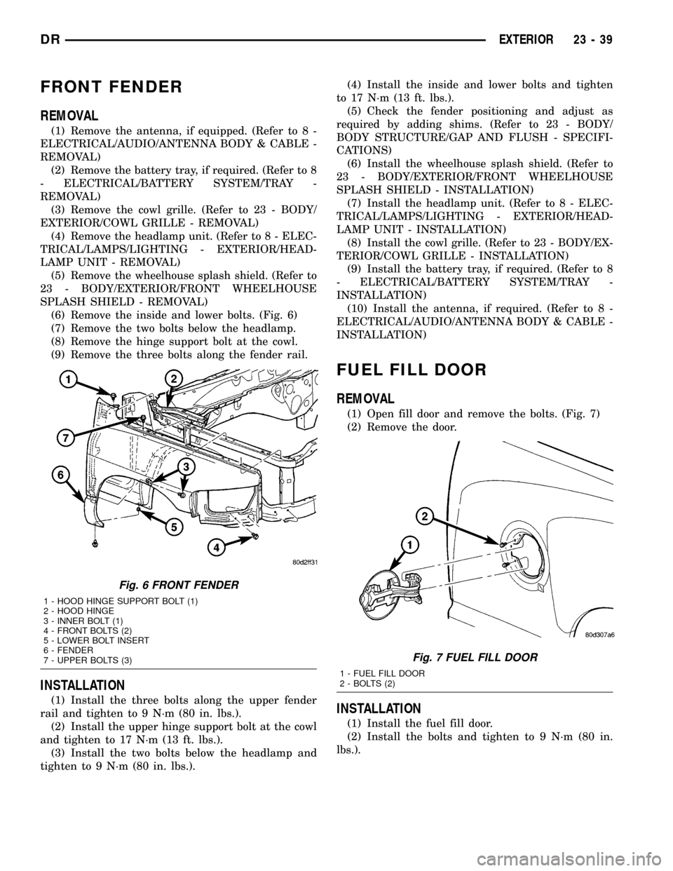
(6) Remove the inside and lower bolts. (Fig. 6)
(7) Remove the two bolts below the headlamp.
(8) Remove the hinge support bolt at the cowl.
(9) Remove the three bolts along the fender rail.
INSTALLATION
(1) Install the three bolts along the upper fender
rail and tighten to 9 N´m (80 in. lbs.).
(2) Install the upper hinge support bolt at the cowl
and tighten to 17 N´m (13 ft. lbs.).
(3) Install the two bolts below the headlamp and
tighten to 9 N´m (80 in. lbs.).(4) Install the inside and lower bolts and tighten
to 17 N´m (13 ft. lbs.).
(5) Check the fender positioning and adjust as
required by adding shims. (Refer to 23 - BODY/
BODY STRUCTURE/GAP AND FLUSH - SPECIFI-
CATIONS)
(6) Install the wheelhouse splash shield. (Refer to
23 - BODY/EXTERIOR/FRONT WHEELHOUSE
SPLASH SHIELD - INSTALLATION)
(7) Install the headlamp unit. (Refer to 8 - ELEC-
TRICAL/LAMPS/LIGHTING - EXTERIOR/HEAD-
LAMP UNIT - INSTALLATION)
(8) Install the cowl grille. (Refer to 23 - BODY/EX-
TERIOR/COWL GRILLE - INSTALLATION)
(9) Install the battery tray, if required. (Refer to 8
- ELECTRICAL/BATTERY SYSTEM/TRAY -
INSTALLATION)
(10) Install the antenna, if required. (Refer to 8 -
ELECTRICAL/AUDIO/ANTENNA BODY & CABLE -
INSTALLATION)
FUEL FILL DOOR
REMOVAL
(1) Open fill door and remove the bolts. (Fig. 7)
(2) Remove the door.
INSTALLATION
(1) Install the fuel fill door.
(2) Install the bolts and tighten to 9 N´m (80 in.
lbs.).
Fig. 6 FRONT FENDER
1 - HOOD HINGE SUPPORT BOLT (1)
2 - HOOD HINGE
3 - INNER BOLT (1)
4 - FRONT BOLTS (2)
5 - LOWER BOLT INSERT
6 - FENDER
7 - UPPER BOLTS (3)
Fig. 7 FUEL FILL DOOR
1 - FUEL FILL DOOR
2 - BOLTS (2)
DREXTERIOR 23 - 39
Page 2339 of 2627
(2) Connect the heated mirror electrical connec-
tors, if equipped.
NOTE: Pressure must be applied equally over the
center portion of the mirror to engage the mirror
glass retaining clip fully.
(3) Position the glass over the motor mounting and
seat fully. Make sure the retaining clip seats fully.
REAR FENDER
REMOVAL
(1) Remove the wheel house splash shield. (Refer
to 23 - BODY/EXTERIOR/REAR WHEELHOUSE
SPLASH SHIELD - REMOVAL)
(2) Disconnect the marker lamps electrical connec-
tors.
(3) Remove the tail lamp units. (Refer to 8 -
ELECTRICAL/LAMPS/LIGHTING - EXTERIOR/
TAIL LAMP UNIT - REMOVAL)
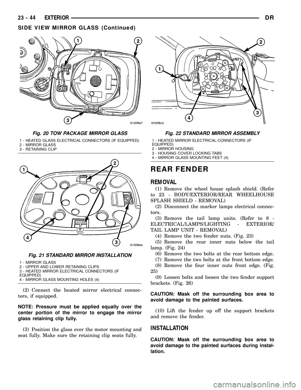
(4) Remove the two fender nuts. (Fig. 23)
(5) Remove the rear inner nuts below the tail
lamp. (Fig. 24)
(6) Remove the two bolts at the rear bottom edge.
(7) Remove the two bolts at the front bottom edge.
(8) Remove the four inner nuts front edge. (Fig.
25)
(9) Loosen bolts and loosen the two fender support
brackets. (Fig. 26)
CAUTION: Mask off the surrounding box area to
avoid damage to the painted surfaces.
(10) Lift the fender up off the support brackets
and remove the fender.
INSTALLATION
CAUTION: Mask off the surrounding box area to
avoid damage to the painted surfaces during instal-
lation.
Fig. 20 TOW PACKAGE MIRROR GLASS
1 - HEATED GLASS ELECTRICAL CONNECTORS (IF EQUIPPED)
2 - MIRROR GLASS
3 - RETAINING CLIP
Fig. 21 STANDARD MIRROR INSTALLATION
1 - MIRROR GLASS
2 - UPPER AND LOWER RETAINING CLIPS
3 - HEATED MIRROR ELECTRICAL CONNECTORS (IF
EQUIPPED)
4 - MIRROR GLASS MOUNTING HOLES (4)
Fig. 22 STANDARD MIRROR ASSEMBLY
1 - HEATED MIRROR ELECTRICAL CONNECTORS (IF
EQUIPPED)
2 - MIRROR HOUSING
3 - HOUSING COVER LOCKING TABS
4 - MIRROR GLASS MOUNTING FEET (4)
23 - 44 EXTERIORDR
SIDE VIEW MIRROR GLASS (Continued)
Page 2340 of 2627
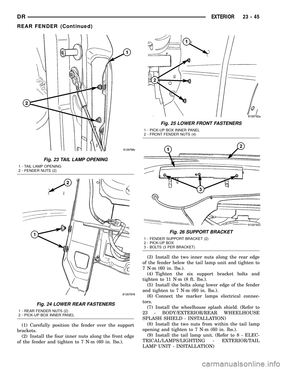
(1) Carefully position the fender over the support
brackets.
(2) Install the four inner nuts along the front edge
of the fender and tighten to 7 N´m (60 in. lbs.).(3) Install the two inner nuts along the rear edge
of the fender below the tail lamp unit and tighten to
7 N´m (60 in. lbs.).
(4) Tighten the six support bracket bolts and
tighten to 11 N´m (8 ft. lbs.).
(5) Install the bolts along lower edge of the fender
and tighten to 7 N´m (60 in. lbs.).
(6) Connect the marker lamps electrical connec-
tors.
(7) Install the wheelhouse splash shield. (Refer to
23 - BODY/EXTERIOR/REAR WHEELHOUSE
SPLASH SHIELD - INSTALLATION)
(8) Install the two nuts from within the tail lamp
opening and tighten to 7 N´m (60 in. lbs.).
(9) Install the tail lamp unit. (Refer to 8 - ELEC-
TRICAL/LAMPS/LIGHTING - EXTERIOR/TAIL
LAMP UNIT - INSTALLATION)
Fig. 23 TAIL LAMP OPENING
1 - TAIL LAMP OPENING
2 - FENDER NUTS (2)
Fig. 24 LOWER REAR FASTENERS
1 - REAR FENDER NUTS (2)
2 - PICK-UP BOX INNER PANEL
Fig. 25 LOWER FRONT FASTENERS
1 - PICK-UP BOX INNER PANEL
2 - FRONT FENDER NUTS (4)
Fig. 26 SUPPORT BRACKET
1 - FENDER SUPPORT BRACKET (2)
2 - PICK-UP BOX
3 - BOLTS (3 PER BRACKET)
DREXTERIOR 23 - 45
REAR FENDER (Continued)
Page 2599 of 2627
ENGINE COOLANT TEMPERATURE
SENSOR - REMOVAL...................7-39
ENGINE COOLANT THERMOSTAT -
3.7L/4.7L - DESCRIPTION...............7-44
ENGINE COOLANT THERMOSTAT -
3.7L/4.7L - INSTALLATION..............7-45
ENGINE COOLANT THERMOSTAT -
3.7L/4.7L - OPERATION.................7-44
ENGINE COOLANT THERMOSTAT -
3.7L/4.7L - REMOVAL..................7-45
ENGINE COOLANT THERMOSTAT - 5.9L
DIESEL - DESCRIPTION................7-46
ENGINE COOLANT THERMOSTAT - 5.9L
DIESEL - INSTALLATION................7-47
ENGINE COOLANT THERMOSTAT - 5.9L
DIESEL - OPERATION..................7-46
ENGINE COOLANT THERMOSTAT - 5.9L
DIESEL - REMOVAL....................7-47
ENGINE COOLANT THERMOSTAT - 8.0L -
DESCRIPTION........................7-48
ENGINE COOLANT THERMOSTAT - 8.0L -
INSTALLATION........................7-49
ENGINE COOLANT THERMOSTAT - 8.0L -
OPERATION..........................7-48
ENGINE COOLANT THERMOSTAT - 8.0L -
REMOVAL...........................7-49
ENGINE COOLANT THERMOSTAT-5.7L -
DESCRIPTION........................7-41
ENGINE COOLANT THERMOSTAT-5.7L -
INSTALLATION........................7-43
ENGINE COOLANT THERMOSTAT-5.7L -
OPERATION..........................7-41
ENGINE COOLANT THERMOSTAT-5.7L -
REMOVAL.............................7-42
ENGINE COOLING SYSTEM
REQUIREMENTS - DESCRIPTION.........24-1
ENGINE COOLING SYSTEM, WARNING....24-42
ENGINE DATA PLATE - DESCRIPTION.....9-248
ENGINE DIAGNOSIS - INTRODUCTION -
DIAGNOSIS AND TESTING......9-183,9-4,9-94
ENGINE DIAGNOSIS - LUBRICATION -
DIAGNOSIS AND TESTING..........9-187,9-7
ENGINE DIAGNOSIS - MECHANICAL -
DIAGNOSIS AND TESTING . . . 9-185,9-188,9-233,
9-6,9-92
ENGINE DIAGNOSIS - PERFORMANCE -
DIAGNOSIS AND TESTING......9-183,9-4,9-90
ENGINE FIRING ORDER, 3.7L V-6.........8I-4
ENGINE FIRING ORDER, 4.7L V-8.........8I-4
ENGINE GASKET SURFACE
PREPARATION - STANDARD
PROCEDURE.........................9-10
ENGINE OIL - DIESEL ENGINES -
DESCRIPTION.........................0-2
ENGINE OIL AND LUBRICANTS -
DESCRIPTION.........................0-1
ENGINE OIL LEAK - DIAGNOSIS AND
TESTING..................9-152,9-220,9-64
ENGINE OIL LEVEL - STANDARD
PROCEDURE........................9-292
ENGINE OIL PRESSURE - DIAGNOSIS
AND TESTING.......................9-289
ENGINE OIL PRESSURE - DIAGNOSIS
AND TESTING, CHECKING.....9-152,9-220,9-65
ENGINE OIL SERVICE - STANDARD
PROCEDURE..........9-153,9-222,9-292,9-71
ENGINE, SPECIAL TOOLS - 4.7L.........9-103
ENGINE, SPECIAL TOOLS - 5.7L.........9-196
ENGINE, SPECIAL TOOLS - 5.9L DIESEL . . 9-246
ENGINE, SPECIFICATIONS - 5.7L........9-192
ENGINE TEMPERATURE GAUGE -
DESCRIPTION.......................8J-24
ENGINE TEMPERATURE GAUGE -
OPERATION.........................8J-24
ENGINE TIMING - VERIFICATION -
STANDARD PROCEDURE...............9-167
ENGINES - CLEANING, RADIATOR FAN -
GAS................................7-34
ENGINES - DESCRIPTION, COOLANT
RECOVERY CONTAINER- GAS
............7-33
ENGINES - DESCRIPTION, ENGINE OIL -
DIESEL
..............................0-2
ENGINES - DESCRIPTION, FAN DRIVE
VISCOUS CLUTCH-GAS
.................7-50
ENGINES - INSPECTION, RADIATOR FAN
- GAS
...............................7-34
ENGINES - INSTALLATION, 3.7, 4.7 AND
5.7L
..........................24-53,24-55ENGINES - INSTALLATION, COOLANT
RECOVERY CONTAINER- GAS............7-33
ENGINES - INSTALLATION, RADIATOR
FAN - GAS...........................7-34
ENGINES - OPERATION, COOLANT
RECOVERY CONTAINER- GAS............7-33
ENGINES - OPERATION, FAN DRIVE
VISCOUS CLUTCH-GAS.................7-50
ENGINES - REMOVAL, 3.7, 4.7 AND 5.7L . 24-52,
24-55
ENGINES - REMOVAL, COOLANT
RECOVERY CONTAINER- GAS............7-33
ENGINES - REMOVAL, RADIATOR FAN -
GAS................................7-33
ENGINES - STANDARD PROCEDURE,
DRAINING COOLING SYSTEM - ALL
GAS................................7-17
ENGINES - STANDARD PROCEDURE,
REFILLING COOLING SYSTEM - ALL
GAS................................7-18
ENHANCED SEATBELT REMINDER
PROGRAMMING - STANDARD
PROCEDURE........................8J-35
ENTRY MODULE - DESCRIPTION,
REMOTE KEYLESS....................8N-7
ENTRY MODULE - DIAGNOSIS AND
TESTING, REMOTE KEYLESS............8N-7
ENTRY MODULE - INSTALLATION,
REMOTE KEYLESS....................8N-8
ENTRY MODULE - OPERATION, REMOTE
KEYLESS............................8N-7
ENTRY MODULE - REMOVAL, REMOTE
KEYLESS............................8N-7
ENTRY TRANSMITTER - DIAGNOSIS AND
TESTING, REMOTE KEYLESS..............8N-8
ENTRY TRANSMITTER -
SPECIFICATIONS, REMOTE KEYLESS......8N-9
EQUIPMENT - STANDARD PROCEDURE,
REFRIGERANT SYSTEM SERVICE........24-46
ERASING TRANSMITTER CODES -
STANDARD PROCEDURE..............8M-12
ETC INDICATOR - DESCRIPTION.........8J-25
ETC INDICATOR - OPERATION..........8J-25
EVACUATE - STANDARD PROCEDURE,
REFRIGERANT SYSTEM...............24-47
EVAP SYSTEM - DESCRIPTION..........25-10
EVAP SYSTEM - TORQUE..............25-11
EVAPORATOR - DESCRIPTION, A/C.......24-59
EVAPORATOR - INSTALLATION, A/C......24-60
EVAPORATOR - OPERATION, A/C........24-59
EVAPORATOR - REMOVAL, A/C..........24-60
EVAPORATOR TEMPERATURE SENSOR -
DESCRIPTION.......................24-22
EVAPORATOR TEMPERATURE SENSOR -
INSTALLATION.......................24-22
EVAPORATOR TEMPERATURE SENSOR -
OPERATION.........................24-22
EVAPORATOR TEMPERATURE SENSOR -
REMOVAL..........................24-22
EVAP/PURGE SOLENOID - DESCRIPTION . . 25-12
EVAP/PURGE SOLENOID - INSTALLATION . 25-12
EVAP/PURGE SOLENOID - OPERATION....25-12
EVAP/PURGE SOLENOID - REMOVAL.....25-12
EXHAUST MANIFOLD - CLEANING . . 9-163,9-226,
9-298
EXHAUST MANIFOLD - DESCRIPTION....9-161,
9-226,9-74
EXHAUST MANIFOLD - INSPECTION.....9-163,
9-227,9-298
EXHAUST MANIFOLD - INSTALLATION . . . 9-164,
9-227,9-298,9-74
EXHAUST MANIFOLD - OPERATION......9-226
EXHAUST MANIFOLD - REMOVAL . . 9-161,9-226,
9-298,9-74
EXHAUST PIPE - INSPECTION.......11-7,11-8
EXTENSION HOUSING BUSHING AND
SEAL - INSTALLATION................21-440
EXTENSION HOUSING BUSHING AND
SEAL - REMOVAL
...................21-440
EXTENSION HOUSING SEAL -
INSTALLATION
. . . 21-128,21-201,21-507,21-536,
21-85
EXTENSION HOUSING SEAL - REMOVAL
. 21-128,
21-201,21-507,21-536,21-85
EXTENSION HOUSING SEAL AND DUST
BOOT - INSTALLATION
.........21-476,21-571
EXTENSION HOUSING SEAL AND DUST
BOOT - REMOVAL
.............21-476,21-571EXTERIOR - DESCRIPTION, LAMPS/
LIGHTING...........................8L-2
EXTERIOR - DIAGNOSIS AND TESTING,
LAMPS/LIGHTING.....................8L-3
EXTERIOR - OPERATION, LAMPS/
LIGHTING...........................8L-2
EXTERIOR HANDLE - INSTALLATION.....23-21,
23-30
EXTERIOR HANDLE - REMOVAL....23-20,23-30
EXTERIOR LAMPS, SPECIFICATIONS......8L-7
EXTERIOR NAME PLATES -
INSTALLATION.......................23-38
EXTERIOR NAME PLATES - REMOVAL....23-38
FAILURE - DIAGNOSIS AND TESTING,
CYLINDER HEAD GASKET..............9-199
FAN - 5.9L DIESEL - CLEANING,
RADIATOR...........................7-35
FAN - 5.9L DIESEL - INSPECTION,
RADIATOR...........................7-35
FAN - 5.9L DIESEL - INSTALLATION,
RADIATOR...........................7-36
FAN - 5.9L DIESEL - REMOVAL,
RADIATOR...........................7-35
FAN - GAS ENGINES - CLEANING,
RADIATOR...........................7-34
FAN - GAS ENGINES - INSPECTION,
RADIATOR...........................7-34
FAN - GAS ENGINES - INSTALLATION,
RADIATOR...........................7-34
FAN - GAS ENGINES - REMOVAL,
RADIATOR...........................7-33
FAN DRIVE - DIAGNOSIS AND TESTING,
ELECTRONICALLY CONTROLLED
VISCOUS............................7-52
FAN DRIVE - DIAGNOSIS AND TESTING,
VISCOUS............................7-50
FAN DRIVE VISCOUS CLUTCH - 5.9L
DIESEL - DESCRIPTION................7-52
FAN DRIVE VISCOUS CLUTCH - 5.9L
DIESEL - OPERATION..................7-52
FAN DRIVE VISCOUS CLUTCH-GAS
ENGINES - DESCRIPTION...............7-50
FAN DRIVE VISCOUS CLUTCH-GAS
ENGINES - OPERATION.................7-50
FASCIA - INSTALLATION, FRONT.........13-3
FASCIA - REMOVAL, FRONT.............13-2
FASTENER IDENTIFICATION -
DESCRIPTION......................Intro.-5
FASTENER USAGE - DESCRIPTION......Intro.-8
FENDER - INSTALLATION, FRONT........23-39
FENDER - INSTALLATION, REAR.........23-44
FENDER - REMOVAL, FRONT...........23-39
FENDER - REMOVAL, REAR............23-44
FENDER MARKER LAMP - INSTALLATION . 8L-18
FENDER MARKER LAMP - REMOVAL.....8L-17
FENDER RAIL REPAIR - STANDARD
PROCEDURE, HYDROFORM............13-11
FILL - STANDARD PROCEDURE,
TRANSMISSION...............21-204,21-368
FILL DOOR - INSTALLATION, FUEL.......23-39
FILL DOOR - REMOVAL, FUEL..........23-39
FILLER CAP - DESCRIPTION, FUEL.......25-13
FILLER CAP - OPERATION, FUEL........25-13
FILTER - INSTALLATION, INLET..........14-20
FILTER - INSTALLATION, OIL . 9-155,9-223,9-293,
9-70
FILTER - REMOVAL, INLET.............14-20
FILTER - REMOVAL, OIL . 9-154,9-223,9-293,9-70
FILTER - STANDARD PROCEDURES,
WATER DRAINING AT FUEL............14-47
FILTER / WATER SEPARATOR -
DESCRIPTION, FUEL..................14-50
FILTER / WATER SEPARATOR -
INSTALLATION, FUEL.................14-50
FILTER / WATER SEPARATOR -
OPERATION, FUEL....................14-50
FILTER / WATER SEPARATOR -
REMOVAL, FUEL.....................14-50
FILTER REPLACEMENT - STANDARD
PROCEDURE, FLUID
...........21-203,21-367
FILTER/PRESSURE REGULATOR -
DESCRIPTION, FUEL
...................14-5
FILTER/PRESSURE REGULATOR -
OPERATION, FUEL
.....................14-6
FINESSE SANDING/BUFFING &
POLISHING - DESCRIPTION
............23-74
FINISH - DESCRIPTION, BASECOAT/
CLEARCOAT
.........................23-73
12 INDEXDR
Description Group-Page Description Group-Page Description Group-Page