1998 DODGE RAM 1500 Valve cover
[x] Cancel search: Valve coverPage 705 of 2627

washer system plumbing (Fig. 3). The check valve is
integral to the washer nozzle plumbing wye fitting
located in the cowl plenum area beneath the cowl
plenum cover/grille panel near the base of the wind-
shield. The check valve consists of a molded plastic
body with a raised arrowhead molded into its center
section that indicates the direction of the flow
through the valve, and three barbed hose nipples
formed in a wye configuration on the outside circum-
ference of the center section of the valve body. The
check valve cannot be adjusted or repaired and, if
faulty or damaged, it must be replaced.
OPERATION
The check valve provides more than one function
in this application. It serves as a wye connector fit-
ting between the engine compartment and washer
nozzle sections of the washer supply hose. It prevents
washer fluid from draining out of the washer supply
hoses back to the washer reservoir. This drain-back
would result in a lengthy delay from when the
washer switch is actuated until washer fluid was dis-
pensed through the washer nozzles, because the
washer pump would have to refill the washer plumb-
ing from the reservoir to the nozzles. Such a drain-
back condition could also result in water, dirt, or
other outside contaminants being siphoned into the
washer system through the washer nozzle orifice.
This water could subsequently freeze and plug the
nozzle, while other contaminants could interfere with
proper nozzle operation and cause improper nozzle
spray patterns. In addition, the check valve prevents
washer fluid from siphoning through the washer noz-
zles after the washer system is turned Off.When the washer pump pressurizes and pumps
washer fluid from the reservoir through the washer
plumbing, the fluid pressure unseats a diaphragm
from over a sump well within the valve by overriding
the spring pressure applied to it by a piston (Fig. 4).
With the diaphragm unseated, washer fluid is
allowed to flow toward the two washer nozzles. When
the washer pump stops operating, the spring pres-
sure on the piston seats the diaphragm over the
sump well in the valve and fluid flow in either direc-
tion within the washer plumbing is prevented. The
check valve cannot be adjusted or repaired and, if
faulty or damaged, it must be replaced.REMOVAL
(1) Remove both wiper arms from the wiper pivots.
(Refer to 8 - ELECTRICAL/WIPERS/WASHERS/
WIPER ARM - REMOVAL).
(2) Unlatch and open the hood.
(3) Remove the cowl plenum cover/grille panel
from over the cowl plenum. (Refer to 23 - BODY/EX-
TERIOR/COWL GRILLE - REMOVAL).
(4) From the underside of the cowl plenum cover/
grille panel, disconnect the cowl plenum and washer
nozzle hoses from the three barbed nipples of the
check valve (Fig. 5).
(5) Remove the check valve from the underside of
the cowl plenum cover/grille panel.
INSTALLATION
(1) Position the check valve to the underside of the
cowl plenum cover/grille panel (Fig. 5). Be certain
that the flow direction arrow molded into the check
valve body is oriented towards the washer nozzles.
Fig. 3 Check Valve
1 - INLET NIPPLE
2 - CHECK VALVE
3 - OUTLET NIPPLE (2)
4 - FLOW DIRECTION ARROW
Fig. 4 Check Valve
1 - SPRING
2 - PISTON
3 - DIAPHRAGM
4 - TO WASHER NOZZLE
5 - FROM WASHER PUMP
8R - 8 WIPERS/WASHERSDR
CHECK VALVE (Continued)
Page 706 of 2627

(2) From the underside of the cowl plenum cover/
grille panel, reconnect the cowl plenum and washer
nozzle hoses to the three barbed nipples of the check
valve.
(3) Reinstall the cowl plenum cover/grille panel
over the cowl plenum. (Refer to 23 - BODY/EXTERI-
OR/COWL GRILLE - INSTALLATION).
(4) Close and latch the hood.
(5) Reinstall both wiper arms onto the wiper piv-
ots. (Refer to 8 - ELECTRICAL/WIPERS/WASHERS/
WIPER ARM - INSTALLATION).
WASHER FLUID LEVEL
SWITCH
DESCRIPTION
The washer fluid level switch is a single pole, sin-
gle throw reed-type switch mounted on the outboard
side of the of the washer reservoir in the engine com-
partment (Fig. 6). Only the molded plastic switch
mounting flange and the integral connector recepta-
cle are visible when the switch is installed in the res-
ervoir. A short nipple formation extends from the
inner surface of the switch mounting flange, and a
barb on the nipple near the switch mounting flange
is pressed through a rubber grommet seal installed
in the mounting hole of the reservoir.
A small, molded plastic float has two pivot pins
near its center that are snapped into two receptacles
near the ends of two stanchions that extend toward
the float from the switch nipple formation. A small
magnet is secured within the end of the float nearestthe switch nipple formation, and a reed switch is con-
cealed within the nipple. A diagnostic resistor is con-
nected between the two switch terminals within the
switch mounting flange. The washer fluid level
switch cannot be adjusted or repaired. If faulty or
damaged, the switch must be replaced.
OPERATION
The washer fluid level switch uses a pivoting,
oblong float to monitor the level of the washer fluid
in the washer reservoir. The float contains a small
magnet. When the float pivots, the proximity of this
magnet to a stationary reed switch within the nipple
formation of the switch changes. When the fluid level
in the washer reservoir is at or above the float level,
the float moves to a vertical position, the influence of
the float magnetic field is removed from the reed
switch, and the normally open reed switch contacts
open. When the fluid level in the washer reservoir
falls below the level of the pivoting float, the float
moves to a horizontal position, the influence of the
float magnetic field is applied to the reed switch, and
the contacts of the normally open reed switch close.
The washer fluid level switch is connected to the
vehicle electrical system through a dedicated take
out and connector of the right (except diesel engines)
or left (diesel engines only) headlamp and dash wire
harness. The switch is connected in series between a
clean ground output of the Front Control Module
Fig. 5 Check Valve Remove/Install
1 - WASHER NOZZLE HOSE (RIGHT)
2 - CHECK VALVE
3 - ROUTING CLIP
4 - COWL PLENUM WASHER HOSE
5 - COWL PLENUM COVER/GRILLE PANEL (UNDERSIDE)
6 - WASHER NOZZLE HOSE (LEFT)
Fig. 6 Washer Fluid Level Switch
1 - MOUNTING FLANGE
2 - BARBED NIPPLE
3 - FLOAT
4 - RESERVOIR
5 - GROMMET SEAL
6 - PIVOT
7 - MAGNET
8 - CONNECTOR RECEPTACLE
DRWIPERS/WASHERS 8R - 9
CHECK VALVE (Continued)
Page 708 of 2627

INSTALLATION
(1) Install a new rubber grommet seal into the
washer fluid level switch mounting hole in the
washer reservoir. Always use a new rubber grommet
seal on the reservoir.
(2) Insert the float of the washer fluid level switch
through the rubber grommet seal and into the
washer reservoir. The connector receptacle of the
washer fluid level switch should be pointed upward.
(3) Using hand pressure, press firmly and evenly
on the washer fluid level switch mounting flange
until the barbed nipple is fully seated in the rubber
grommet seal in the washer reservoir mounting hole.
(4) Reconnect the right (except diesel engine) or
left (diesel engine only) headlamp and dash wire har-
ness connector for the washer fluid level switch to
the switch connector receptacle (Fig. 7) or (Fig. 8).
(5) Reconnect the removed washer hose to the
barbed outlet nipple of the washer pump/motor unit.
(6) Refill the washer reservoir with the washer
fluid drained from the reservoir during the removal
procedure.
(7) Reconnect the battery negative cable.
(8) Close and latch the hood.
WASHER HOSES/TUBES
DESCRIPTION
The washer plumbing consists of a small diameter
rubber reservoir washer hose that is routed from the
barbed outlet nipple of the electric washer pump/mo-tor unit on the washer reservoir through a trough
molded into the back of the reservoir above the
washer pump and to the engine compartment washer
hose (Fig. 9). On models equipped with an optional
diesel engine, the reservoir washer hose is routed
through routing clips on the top of the radiator fan
shroud from the washer reservoir on the left side of
the radiator to the engine compartment washer hose
on the right side of the radiator. The engine compart-
ment washer hose is contained within the right head-
lamp and dash wire harness, which is routed through
the engine compartment along the top of the right
front fender wheel house to the dash panel.
The engine compartment washer hose is connected
to the washer reservoir washer hose and to the cowl
plenum washer hose with molded plastic in-line fit-
tings that have a barbed nipple on each end. The
cowl plenum washer hose is routed from the engine
compartment into the cowl plenum area through a
trough formation located near the right end of the
cowl plenum cover/grille panel. The cowl plenum
washer hose is connected to the washer system check
valve/wye fitting on the underside of the cowl plenum
cover/grille panel. The cowl plenum washer hose and
the two washer nozzle hoses are routed through inte-
gral routing clips on the underside of the cowl ple-
num cover/grille panel. The cowl plenum washer hose
is connected to one nipple on the wye fitting and the
two washer nozzle hoses are connected to the other
two wye fitting nipples. The washer nozzle hoses are
then routed along the underside of the cowl plenum
cover/grille panel to the two washer nozzles.
Washer hose is available for service only as roll
stock, which must then be cut to length. The molded
plastic washer hose fittings cannot be repaired. If
these fittings are faulty or damaged, they must be
replaced.
OPERATION
Washer fluid in the washer reservoir is pressurized
and fed by the washer pump/motor through the
washer system plumbing and fittings to the two
washer nozzles. Whenever routing the washer hose
or a wire harness containing a washer hose, it must
be routed away from hot, sharp, or moving parts;
and, sharp bends that might pinch the hose must be
avoided.
WASHER NOZZLE
DESCRIPTION
The two washer nozzles have integral snap fea-
tures and an anti-rotation tab that secure them in
dedicated holes in the cowl plenum cover/grille panel
located near the base of the windshield (Fig. 10). The
Fig. 9 Engine Compartment Washer Hose
1 - RIGHT FENDER
2 - RIGHT HEADLAMP & DASH WIRE HARNESS
3 - ENGINE COMPARTMENT WASHER HOSE (TO COWL
PLENUM)
4 - COWL PLENUM WASHER HOSE
5 - ENGINE COMPARTMENT WASHER HOSE (TO WASHER
RESERVOIR)
DRWIPERS/WASHERS 8R - 11
WASHER FLUID LEVEL SWITCH (Continued)
Page 1224 of 2627
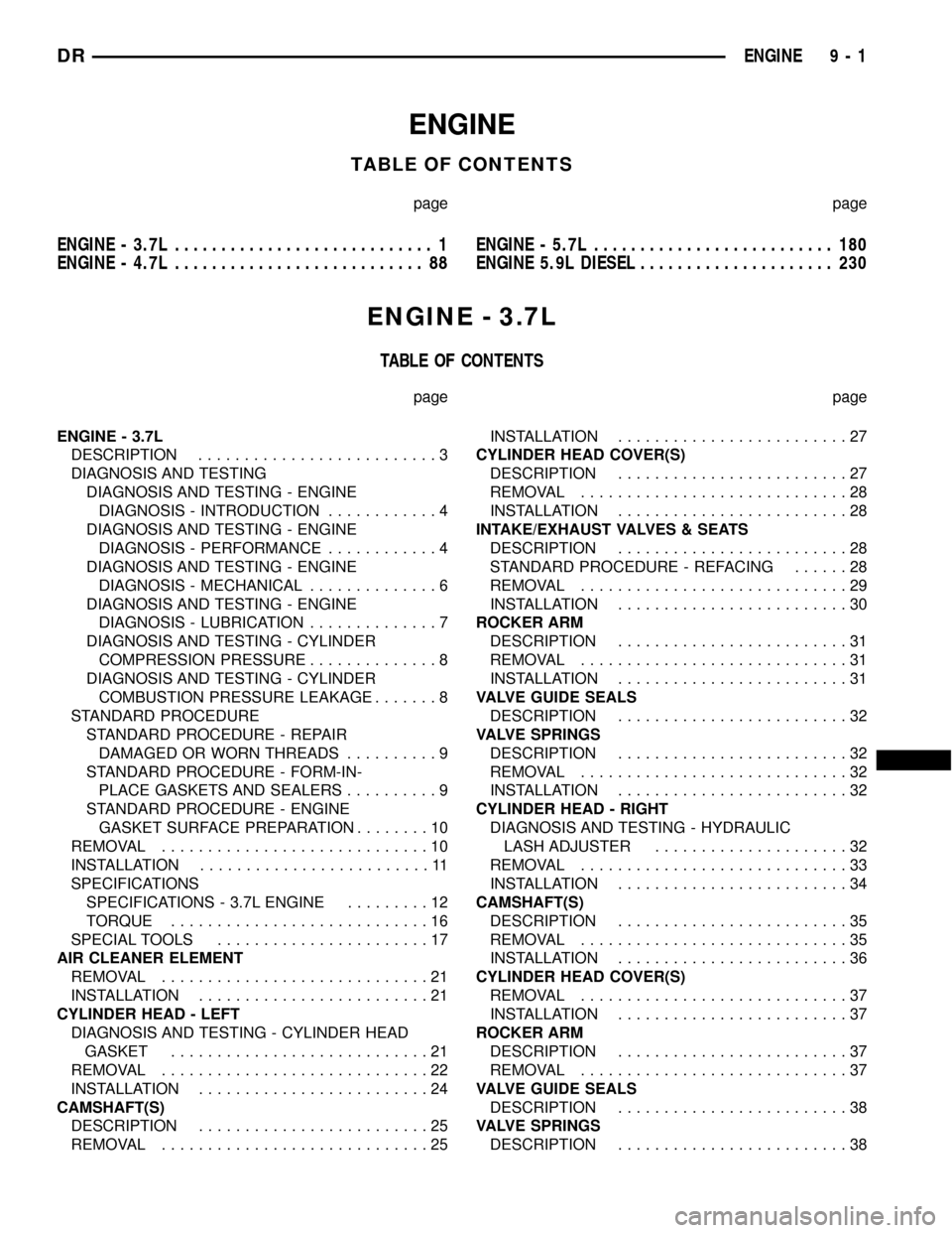
ENGINE
TABLE OF CONTENTS
page page
ENGINE - 3.7L............................ 1
ENGINE - 4.7L........................... 88ENGINE - 5.7L.......................... 180
ENGINE 5.9L DIESEL..................... 230
ENGINE - 3.7L
TABLE OF CONTENTS
page page
ENGINE - 3.7L
DESCRIPTION..........................3
DIAGNOSIS AND TESTING
DIAGNOSIS AND TESTING - ENGINE
DIAGNOSIS - INTRODUCTION............4
DIAGNOSIS AND TESTING - ENGINE
DIAGNOSIS - PERFORMANCE............4
DIAGNOSIS AND TESTING - ENGINE
DIAGNOSIS - MECHANICAL..............6
DIAGNOSIS AND TESTING - ENGINE
DIAGNOSIS - LUBRICATION..............7
DIAGNOSIS AND TESTING - CYLINDER
COMPRESSION PRESSURE..............8
DIAGNOSIS AND TESTING - CYLINDER
COMBUSTION PRESSURE LEAKAGE.......8
STANDARD PROCEDURE
STANDARD PROCEDURE - REPAIR
DAMAGED OR WORN THREADS..........9
STANDARD PROCEDURE - FORM-IN-
PLACE GASKETS AND SEALERS..........9
STANDARD PROCEDURE - ENGINE
GASKET SURFACE PREPARATION........10
REMOVAL.............................10
INSTALLATION.........................11
SPECIFICATIONS
SPECIFICATIONS - 3.7L ENGINE.........12
TORQUE............................16
SPECIAL TOOLS.......................17
AIR CLEANER ELEMENT
REMOVAL.............................21
INSTALLATION.........................21
CYLINDER HEAD - LEFT
DIAGNOSIS AND TESTING - CYLINDER HEAD
GASKET............................21
REMOVAL.............................22
INSTALLATION.........................24
CAMSHAFT(S)
DESCRIPTION.........................25
REMOVAL.............................25INSTALLATION.........................27
CYLINDER HEAD COVER(S)
DESCRIPTION.........................27
REMOVAL.............................28
INSTALLATION.........................28
INTAKE/EXHAUST VALVES & SEATS
DESCRIPTION.........................28
STANDARD PROCEDURE - REFACING......28
REMOVAL.............................29
INSTALLATION.........................30
ROCKER ARM
DESCRIPTION.........................31
REMOVAL.............................31
INSTALLATION.........................31
VALVE GUIDE SEALS
DESCRIPTION.........................32
VALVE SPRINGS
DESCRIPTION.........................32
REMOVAL.............................32
INSTALLATION.........................32
CYLINDER HEAD - RIGHT
DIAGNOSIS AND TESTING - HYDRAULIC
LASH ADJUSTER.....................32
REMOVAL.............................33
INSTALLATION.........................34
CAMSHAFT(S)
DESCRIPTION.........................35
REMOVAL.............................35
INSTALLATION.........................36
CYLINDER HEAD COVER(S)
REMOVAL.............................37
INSTALLATION.........................37
ROCKER ARM
DESCRIPTION.........................37
REMOVAL.............................37
VALVE GUIDE SEALS
DESCRIPTION.........................38
VALVE SPRINGS
DESCRIPTION.........................38
DRENGINE 9 - 1
Page 1225 of 2627
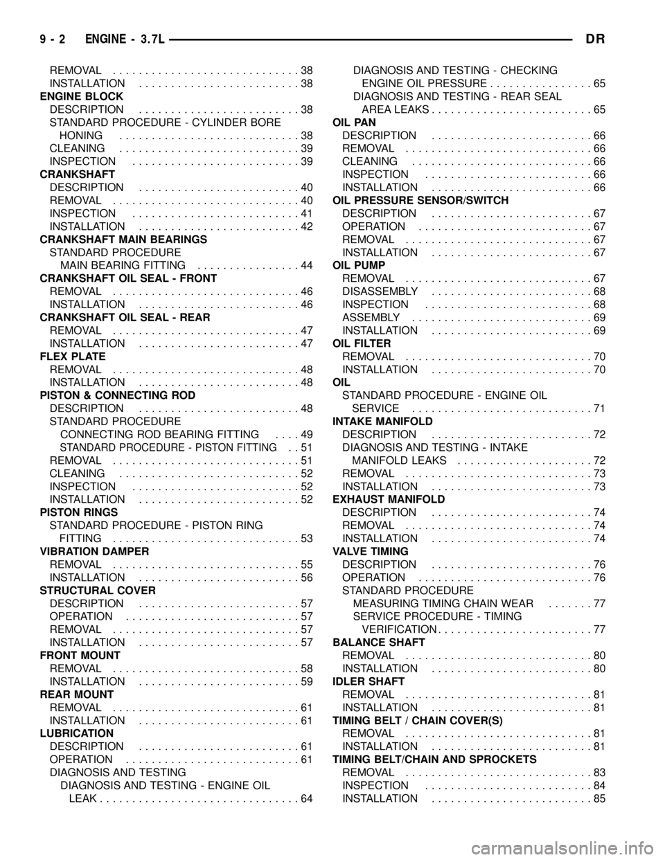
REMOVAL.............................38
INSTALLATION.........................38
ENGINE BLOCK
DESCRIPTION.........................38
STANDARD PROCEDURE - CYLINDER BORE
HONING............................38
CLEANING............................39
INSPECTION..........................39
CRANKSHAFT
DESCRIPTION.........................40
REMOVAL.............................40
INSPECTION..........................41
INSTALLATION.........................42
CRANKSHAFT MAIN BEARINGS
STANDARD PROCEDURE
MAIN BEARING FITTING................44
CRANKSHAFT OIL SEAL - FRONT
REMOVAL.............................46
INSTALLATION.........................46
CRANKSHAFT OIL SEAL - REAR
REMOVAL.............................47
INSTALLATION.........................47
FLEX PLATE
REMOVAL.............................48
INSTALLATION.........................48
PISTON & CONNECTING ROD
DESCRIPTION.........................48
STANDARD PROCEDURE
CONNECTING ROD BEARING FITTING....49
STANDARD PROCEDURE - PISTON FITTING..51
REMOVAL.............................51
CLEANING............................52
INSPECTION..........................52
INSTALLATION.........................52
PISTON RINGS
STANDARD PROCEDURE - PISTON RING
FITTING.............................53
VIBRATION DAMPER
REMOVAL.............................55
INSTALLATION.........................56
STRUCTURAL COVER
DESCRIPTION.........................57
OPERATION...........................57
REMOVAL.............................57
INSTALLATION.........................57
FRONT MOUNT
REMOVAL.............................58
INSTALLATION.........................59
REAR MOUNT
REMOVAL.............................61
INSTALLATION.........................61
LUBRICATION
DESCRIPTION.........................61
OPERATION...........................61
DIAGNOSIS AND TESTING
DIAGNOSIS AND TESTING - ENGINE OIL
LEAK...............................64DIAGNOSIS AND TESTING - CHECKING
ENGINE OIL PRESSURE................65
DIAGNOSIS AND TESTING - REAR SEAL
AREA LEAKS.........................65
OIL PAN
DESCRIPTION.........................66
REMOVAL.............................66
CLEANING............................66
INSPECTION..........................66
INSTALLATION.........................66
OIL PRESSURE SENSOR/SWITCH
DESCRIPTION.........................67
OPERATION...........................67
REMOVAL.............................67
INSTALLATION.........................67
OIL PUMP
REMOVAL.............................67
DISASSEMBLY.........................68
INSPECTION..........................68
ASSEMBLY............................69
INSTALLATION.........................69
OIL FILTER
REMOVAL.............................70
INSTALLATION.........................70
OIL
STANDARD PROCEDURE - ENGINE OIL
SERVICE............................71
INTAKE MANIFOLD
DESCRIPTION.........................72
DIAGNOSIS AND TESTING - INTAKE
MANIFOLD LEAKS.....................72
REMOVAL.............................73
INSTALLATION.........................73
EXHAUST MANIFOLD
DESCRIPTION.........................74
REMOVAL.............................74
INSTALLATION.........................74
VALVE TIMING
DESCRIPTION.........................76
OPERATION...........................76
STANDARD PROCEDURE
MEASURING TIMING CHAIN WEAR.......77
SERVICE PROCEDURE - TIMING
VERIFICATION........................77
BALANCE SHAFT
REMOVAL.............................80
INSTALLATION.........................80
IDLER SHAFT
REMOVAL.............................81
INSTALLATION.........................81
TIMING BELT / CHAIN COVER(S)
REMOVAL.............................81
INSTALLATION.........................81
TIMING BELT/CHAIN AND SPROCKETS
REMOVAL.............................83
INSPECTION..........................84
INSTALLATION.........................85
9 - 2 ENGINE - 3.7LDR
Page 1230 of 2627
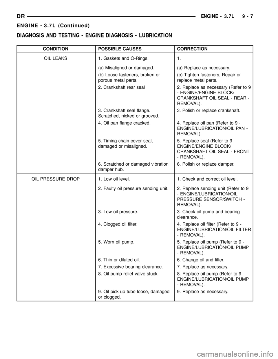
DIAGNOSIS AND TESTING - ENGINE DIAGNOSIS - LUBRICATION
CONDITION POSSIBLE CAUSES CORRECTION
OIL LEAKS 1. Gaskets and O-Rings. 1.
(a) Misaligned or damaged. (a) Replace as necessary.
(b) Loose fasteners, broken or
porous metal parts.(b) Tighten fasteners, Repair or
replace metal parts.
2. Crankshaft rear seal 2. Replace as necessary (Refer to 9
- ENGINE/ENGINE BLOCK/
CRANKSHAFT OIL SEAL - REAR -
REMOVAL).
3. Crankshaft seal flange.
Scratched, nicked or grooved.3. Polish or replace crankshaft.
4. Oil pan flange cracked. 4. Replace oil pan (Refer to 9 -
ENGINE/LUBRICATION/OIL PAN -
REMOVAL).
5. Timing chain cover seal,
damaged or misaligned.5. Replace seal (Refer to 9 -
ENGINE/ENGINE BLOCK/
CRANKSHAFT OIL SEAL - FRONT
- REMOVAL).
6. Scratched or damaged vibration
damper hub.6. Polish or replace damper.
OIL PRESSURE DROP 1. Low oil level. 1. Check and correct oil level.
2. Faulty oil pressure sending unit. 2. Replace sending unit (Refer to 9
- ENGINE/LUBRICATION/OIL
PRESSURE SENSOR/SWITCH -
REMOVAL).
3. Low oil pressure. 3. Check oil pump and bearing
clearance.
4. Clogged oil filter. 4. Replace oil filter (Refer to 9 -
ENGINE/LUBRICATION/OIL FILTER
- REMOVAL).
5. Worn oil pump. 5. Replace oil pump (Refer to 9 -
ENGINE/LUBRICATION/OIL PUMP
- REMOVAL).
6. Thin or diluted oil. 6. Change oil and filter.
7. Excessive bearing clearance. 7. Replace as necessary.
8. Oil pump relief valve stuck. 8. Replace oil pump (Refer to 9 -
ENGINE/LUBRICATION/OIL PUMP
- REMOVAL).
9. Oil pick up tube loose, damaged
or clogged.9. Replace as necessary.
DRENGINE - 3.7L 9 - 7
ENGINE - 3.7L (Continued)
Page 1232 of 2627
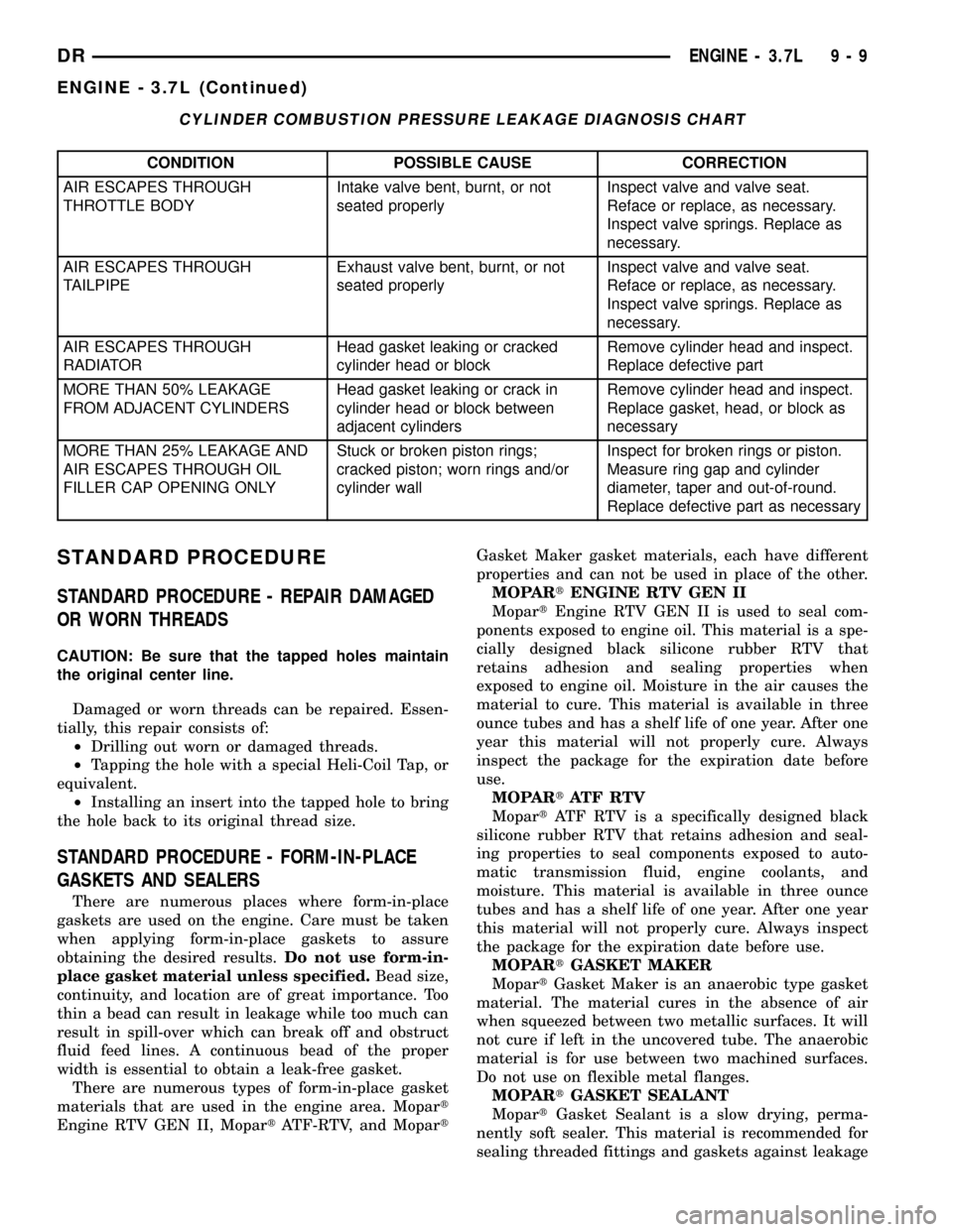
CYLINDER COMBUSTION PRESSURE LEAKAGE DIAGNOSIS CHART
CONDITION POSSIBLE CAUSE CORRECTION
AIR ESCAPES THROUGH
THROTTLE BODYIntake valve bent, burnt, or not
seated properlyInspect valve and valve seat.
Reface or replace, as necessary.
Inspect valve springs. Replace as
necessary.
AIR ESCAPES THROUGH
TAILPIPEExhaust valve bent, burnt, or not
seated properlyInspect valve and valve seat.
Reface or replace, as necessary.
Inspect valve springs. Replace as
necessary.
AIR ESCAPES THROUGH
RADIATORHead gasket leaking or cracked
cylinder head or blockRemove cylinder head and inspect.
Replace defective part
MORE THAN 50% LEAKAGE
FROM ADJACENT CYLINDERSHead gasket leaking or crack in
cylinder head or block between
adjacent cylindersRemove cylinder head and inspect.
Replace gasket, head, or block as
necessary
MORE THAN 25% LEAKAGE AND
AIR ESCAPES THROUGH OIL
FILLER CAP OPENING ONLYStuck or broken piston rings;
cracked piston; worn rings and/or
cylinder wallInspect for broken rings or piston.
Measure ring gap and cylinder
diameter, taper and out-of-round.
Replace defective part as necessary
STANDARD PROCEDURE
STANDARD PROCEDURE - REPAIR DAMAGED
OR WORN THREADS
CAUTION: Be sure that the tapped holes maintain
the original center line.
Damaged or worn threads can be repaired. Essen-
tially, this repair consists of:
²Drilling out worn or damaged threads.
²Tapping the hole with a special Heli-Coil Tap, or
equivalent.
²Installing an insert into the tapped hole to bring
the hole back to its original thread size.
STANDARD PROCEDURE - FORM-IN-PLACE
GASKETS AND SEALERS
There are numerous places where form-in-place
gaskets are used on the engine. Care must be taken
when applying form-in-place gaskets to assure
obtaining the desired results.Do not use form-in-
place gasket material unless specified.Bead size,
continuity, and location are of great importance. Too
thin a bead can result in leakage while too much can
result in spill-over which can break off and obstruct
fluid feed lines. A continuous bead of the proper
width is essential to obtain a leak-free gasket.
There are numerous types of form-in-place gasket
materials that are used in the engine area. Mopart
Engine RTV GEN II, MopartATF-RTV, and MopartGasket Maker gasket materials, each have different
properties and can not be used in place of the other.
MOPARtENGINE RTV GEN II
MopartEngine RTV GEN II is used to seal com-
ponents exposed to engine oil. This material is a spe-
cially designed black silicone rubber RTV that
retains adhesion and sealing properties when
exposed to engine oil. Moisture in the air causes the
material to cure. This material is available in three
ounce tubes and has a shelf life of one year. After one
year this material will not properly cure. Always
inspect the package for the expiration date before
use.
MOPARtATF RTV
MopartATF RTV is a specifically designed black
silicone rubber RTV that retains adhesion and seal-
ing properties to seal components exposed to auto-
matic transmission fluid, engine coolants, and
moisture. This material is available in three ounce
tubes and has a shelf life of one year. After one year
this material will not properly cure. Always inspect
the package for the expiration date before use.
MOPARtGASKET MAKER
MopartGasket Maker is an anaerobic type gasket
material. The material cures in the absence of air
when squeezed between two metallic surfaces. It will
not cure if left in the uncovered tube. The anaerobic
material is for use between two machined surfaces.
Do not use on flexible metal flanges.
MOPARtGASKET SEALANT
MopartGasket Sealant is a slow drying, perma-
nently soft sealer. This material is recommended for
sealing threaded fittings and gaskets against leakage
DRENGINE - 3.7L 9 - 9
ENGINE - 3.7L (Continued)
Page 1235 of 2627
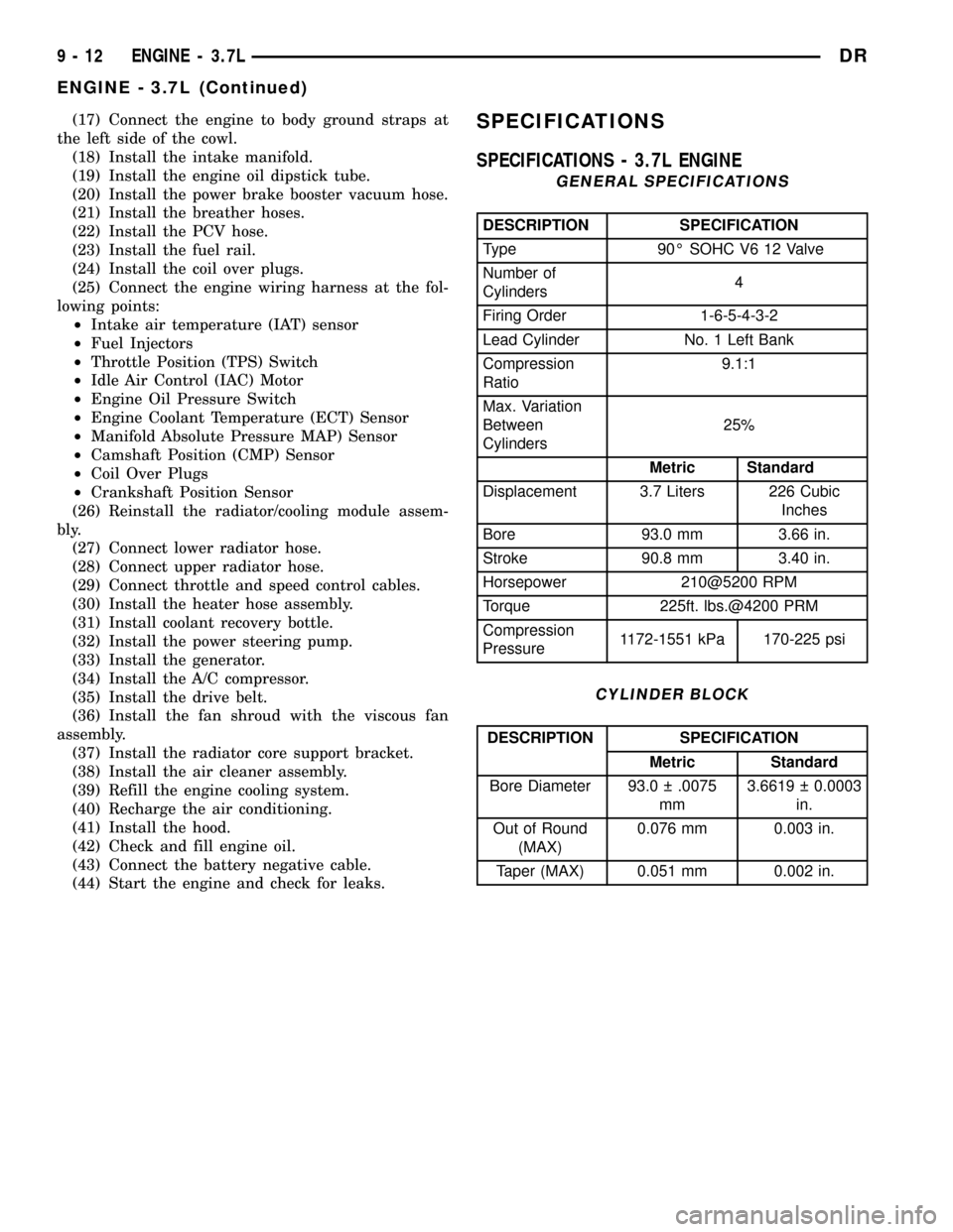
(17) Connect the engine to body ground straps at
the left side of the cowl.
(18) Install the intake manifold.
(19) Install the engine oil dipstick tube.
(20) Install the power brake booster vacuum hose.
(21) Install the breather hoses.
(22) Install the PCV hose.
(23) Install the fuel rail.
(24) Install the coil over plugs.
(25) Connect the engine wiring harness at the fol-
lowing points:
²Intake air temperature (IAT) sensor
²Fuel Injectors
²Throttle Position (TPS) Switch
²Idle Air Control (IAC) Motor
²Engine Oil Pressure Switch
²Engine Coolant Temperature (ECT) Sensor
²Manifold Absolute Pressure MAP) Sensor
²Camshaft Position (CMP) Sensor
²Coil Over Plugs
²Crankshaft Position Sensor
(26) Reinstall the radiator/cooling module assem-
bly.
(27) Connect lower radiator hose.
(28) Connect upper radiator hose.
(29) Connect throttle and speed control cables.
(30) Install the heater hose assembly.
(31) Install coolant recovery bottle.
(32) Install the power steering pump.
(33) Install the generator.
(34) Install the A/C compressor.
(35) Install the drive belt.
(36) Install the fan shroud with the viscous fan
assembly.
(37) Install the radiator core support bracket.
(38) Install the air cleaner assembly.
(39) Refill the engine cooling system.
(40) Recharge the air conditioning.
(41) Install the hood.
(42) Check and fill engine oil.
(43) Connect the battery negative cable.
(44) Start the engine and check for leaks.SPECIFICATIONS
SPECIFICATIONS - 3.7L ENGINE
GENERAL SPECIFICATIONS
DESCRIPTION SPECIFICATION
Type 90É SOHC V6 12 Valve
Number of
Cylinders4
Firing Order 1-6-5-4-3-2
Lead Cylinder No. 1 Left Bank
Compression
Ratio9.1:1
Max. Variation
Between
Cylinders25%
Metric Standard
Displacement 3.7 Liters 226 Cubic
Inches
Bore 93.0 mm 3.66 in.
Stroke 90.8 mm 3.40 in.
Horsepower 210@5200 RPM
Torque 225ft. lbs.@4200 PRM
Compression
Pressure1172-1551 kPa 170-225 psi
CYLINDER BLOCK
DESCRIPTION SPECIFICATION
Metric Standard
Bore Diameter 93.0 .0075
mm3.6619 0.0003
in.
Out of Round
(MAX)0.076 mm 0.003 in.
Taper (MAX) 0.051 mm 0.002 in.
9 - 12 ENGINE - 3.7LDR
ENGINE - 3.7L (Continued)