1998 DODGE RAM 1500 Removal
[x] Cancel search: RemovalPage 62 of 2627

INSTALLATION
CAUTION: The left and right side torsion bars are
NOT interchangeable. The bars are identified and
stamped R or L, for right or left. The bars do not
have a front or rear end and can be installed with
either end facing forward.
(1) Insert torsion bar ends into anchor and suspen-
sion arm.
(2) Position the anchor in the frame crossmember.
(3) Install Special Tool - 8686 to the anchor and
the crossmember (Fig. 30).
(4) Increase the tension on the anchor in order to
load the torsion bar.
(5) Install the adjustment bolt and the adjuster
nut.
(6) Turn adjustment bolt clockwise the recorded
amount of turns.
(7) Remove tool - 8686 from the torsion bar cross-
member (Fig. 30).
(8) Install the transfer case skid plate (Refer to 13
- FRAME & BUMPERS/FRAME/TRANSFER CASE
SKID PLATE - INSTALLATION).
(9) Lower vehicle and adjust the front suspension
height (Refer to 2 - SUSPENSION/WHEEL ALIGN-
MENT - STANDARD PROCEDURE).
(10) Perform a wheel alignment (Refer to 2 - SUS-
PENSION/WHEEL ALIGNMENT - STANDARD
PROCEDURE).
UPPER BALL JOINT
DIAGNOSIS AND TESTING - UPPER BALL
JOINT
NOTE: If the ball joint is equipped with a lubrication
fitting, grease the joint then road test the vehicle
before performing test.
(1) Raise the front of the vehicle. Place safety floor
stands under both lower control arms as far outboard
as possible. Lower the vehicle to allow the stands to
support some or all of the vehicle weight.
(2) Remove the front tires.(3) Mount a dial indicator solidly to the frame and
then zero the dial indicator.
(4) Position dial indicator plunger on the topside of
the upper ball joint (Fig. 32).
NOTE: The dial indicator plunger must be perpen-
dicular to the machined surface of the ball joint
(Fig. 32).
NOTE: Use care not to pry or tear the ball joint
boot, when checking the free play.
(5) Position a pry bar between the steering
knuckle and the upper control arm. Pry upwards on
the upper control arm (Fig. 32).
(6) If the travel exceeds 0.5 mm (0.020 in.), replace
the upper control arm since the upper ball joint is
integral to the arm (Refer to 2 - SUSPENSION/
FRONT/UPPER CONTROL ARM - REMOVAL).
(7) If the upper ball joint is within specs reinstall
the front tires (Refer to 22 - TIRES/WHEELS/
WHEELS - STANDARD PROCEDURE).
Fig. 32 UPPER BALL JOINT PLAY
1 - DIAL INDICATOR
2 - UPPER CONTROL ARM
3-PRYBAR
4 - KNUCKLE
5 - BALL JOINT BOOT
DRFRONT - INDEPENDENT FRONT SUSPENSION 2 - 27
TORSION BAR (Continued)
Page 63 of 2627

UPPER CONTROL ARM
REMOVAL
(1) Raise and support vehicle.
(2) Remove wheel and tire assembly.
(3) Remove the nut from upper ball joint.
(4) Separate upper ball joint from the steering
knuckle with Remover 8677 (Fig. 33)
CAUTION: When installing Remover 8677 to sepa-
rate the ball joint, be careful not to damage the ball
joint seal.(5) Remove the control arm pivot bolts and remove
control arm (Fig. 34).
INSTALLATION
(1) Position the control arm into the frame brack-
ets. Install bolts and tighten to 132 N´m (97 ft.
lbs.)(LD) or 170 N´m (125 ft. lbs.)(HD 4X2 only).
(2) Insert the ball joint in steering knuckle and
tighten the upper ball joint nut to 54 N´m (40 ft.
lbs.)(on 1500 series only an additional 90É turn is
required).
(3) Install the wheel and tire assembly,(Refer to 22
- TIRES/WHEELS/WHEELS - STANDARD PROCE-
DURE).
(4) Remove the support and lower vehicle.
(5) Perform a wheel alignment, (Refer to 2 - SUS-
PENSION/WHEEL ALIGNMENT - STANDARD
PROCEDURE).
Fig. 33 UPPER BALL JOINT SEPARATION
1 - UPPER CONTROL ARM
2 - REMOVER
3 - STEERING KNUCKLE
Fig. 34 UPPER CONTROL ARM
1 - REAR PIVOT BOLT
2 - FRONT PIVOT BOLT
3 - UPPER CONTROL ARM
2 - 28 FRONT - INDEPENDENT FRONT SUSPENSIONDR
Page 64 of 2627

FRONT - LINK/COIL
TABLE OF CONTENTS
page page
FRONT - LINK/COIL
SPECIFICATIONS
TORQUE CHART......................29
SPECIAL TOOLS
91/4AA ............................30
HUB / BEARING
REMOVAL.............................31
INSTALLATION.........................32
LOWER BALL JOINT
DIAGNOSIS AND TESTING - LOWER BALL
JOINT..............................34
REMOVAL.............................35
INSTALLATION.........................35
UPPER BALL JOINT
DIAGNOSIS AND TESTING - UPPER BALL
JOINT..............................36
REMOVAL.............................36
INSTALLATION.........................36
KNUCKLE
REMOVAL.............................37
INSTALLATION.........................37UPPER SUSPENSION ARM
REMOVAL
REMOVAL - LEFT.....................37
REMOVAL - RIGHT....................37
INSTALLATION
INSTALLATION - LEFT..................37
INSTALLATION - RIGHT................37
LOWER SUSPENSION ARM
REMOVAL.............................38
INSTALLATION.........................38
SHOCK
DIAGNOSIS AND TESTING - SHOCK........38
REMOVAL.............................38
INSTALLATION.........................38
SPRING
REMOVAL.............................39
INSTALLATION.........................39
STABILIZER BAR
REMOVAL.............................39
INSTALLATION.........................40
FRONT - LINK/COIL
SPECIFICATIONS
TORQUE CHART
TORQUE SPECIFICATIONS
DESCRIPTION N´m Ft. Lbs. In. Lbs.
Shock Absorber
Upper Nut54 40 Ð
Shock Absorber
Lower Bolt136 100 Ð
Lower Suspension Arm
Frame Nuts217 160 Ð
Lower Suspension Arm
Axle Nut217 160 Ð
Upper Suspension Arm
Frame Nuts149 110 Ð
Upper Suspension Arm
Axle Nut149 110 Ð
DRFRONT - LINK/COIL 2 - 29
Page 66 of 2627

HUB / BEARING
REMOVAL
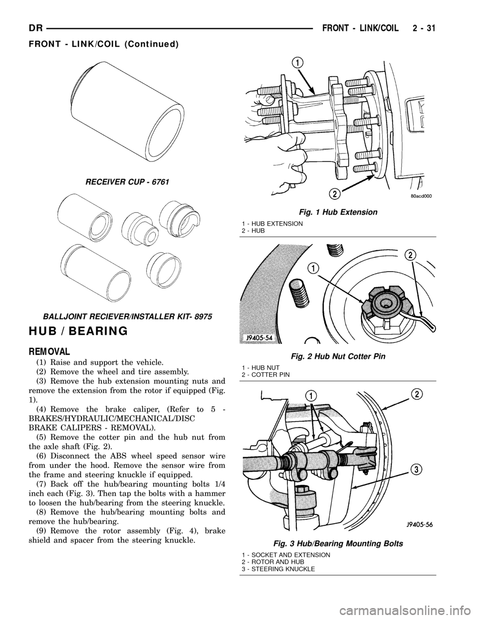
(1) Raise and support the vehicle.
(2) Remove the wheel and tire assembly.
(3) Remove the hub extension mounting nuts and
remove the extension from the rotor if equipped (Fig.
1).
(4) Remove the brake caliper, (Refer to 5 -
BRAKES/HYDRAULIC/MECHANICAL/DISC
BRAKE CALIPERS - REMOVAL).
(5) Remove the cotter pin and the hub nut from
the axle shaft (Fig. 2).
(6) Disconnect the ABS wheel speed sensor wire
from under the hood. Remove the sensor wire from
the frame and steering knuckle if equipped.
(7) Back off the hub/bearing mounting bolts 1/4
inch each (Fig. 3). Then tap the bolts with a hammer
to loosen the hub/bearing from the steering knuckle.
(8) Remove the hub/bearing mounting bolts and
remove the hub/bearing.
(9) Remove the rotor assembly (Fig. 4), brake
shield and spacer from the steering knuckle.
RECEIVER CUP - 6761
BALLJOINT RECIEVER/INSTALLER KIT- 8975
Fig. 1 Hub Extension
1 - HUB EXTENSION
2 - HUB
Fig. 2 Hub Nut Cotter Pin
1 - HUB NUT
2 - COTTER PIN
Fig. 3 Hub/Bearing Mounting Bolts
1 - SOCKET AND EXTENSION
2 - ROTOR AND HUB
3 - STEERING KNUCKLE
DRFRONT - LINK/COIL 2 - 31
FRONT - LINK/COIL (Continued)
Page 69 of 2627

LOWER BALL JOINT
DIAGNOSIS AND TESTING - LOWER BALL
JOINT
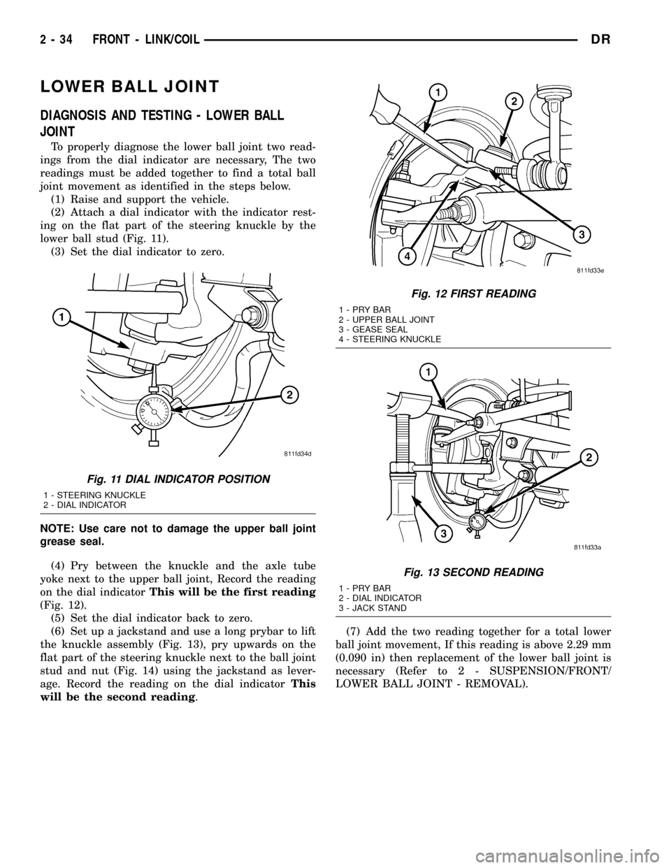
To properly diagnose the lower ball joint two read-
ings from the dial indicator are necessary, The two
readings must be added together to find a total ball
joint movement as identified in the steps below.
(1) Raise and support the vehicle.
(2) Attach a dial indicator with the indicator rest-
ing on the flat part of the steering knuckle by the
lower ball stud (Fig. 11).
(3) Set the dial indicator to zero.
NOTE: Use care not to damage the upper ball joint
grease seal.
(4) Pry between the knuckle and the axle tube
yoke next to the upper ball joint, Record the reading
on the dial indicatorThis will be the first reading
(Fig. 12).
(5) Set the dial indicator back to zero.
(6) Set up a jackstand and use a long prybar to lift
the knuckle assembly (Fig. 13), pry upwards on the
flat part of the steering knuckle next to the ball joint
stud and nut (Fig. 14) using the jackstand as lever-
age. Record the reading on the dial indicatorThis
will be the second reading.(7) Add the two reading together for a total lower
ball joint movement, If this reading is above 2.29 mm
(0.090 in) then replacement of the lower ball joint is
necessary (Refer to 2 - SUSPENSION/FRONT/
LOWER BALL JOINT - REMOVAL).
Fig. 11 DIAL INDICATOR POSITION
1 - STEERING KNUCKLE
2 - DIAL INDICATOR
Fig. 12 FIRST READING
1-PRYBAR
2 - UPPER BALL JOINT
3 - GEASE SEAL
4 - STEERING KNUCKLE
Fig. 13 SECOND READING
1-PRYBAR
2 - DIAL INDICATOR
3 - JACK STAND
2 - 34 FRONT - LINK/COILDR
Page 70 of 2627

REMOVAL
(1) Remove lower snap ring from the lower ball
joint (Fig. 15).
(2) Position special tool 8975±2 (RECEIVER) and
8975±4 (DRIVER) with tool C4212±F as shown to
remove lower ball stud (Fig. 16).
INSTALLATION
(1) Position special tool 8975±1 (DRIVER) and
8975±3 (RECEIVER) with C4212±F as shown to
install lower ball stud (Fig. 17).
Fig. 14 PRYING LOCATION
1-PRYBAR
2 - UPPER BALL JOINT
3 - AXLE YOKE
4 - GRESE SEAL
5 - STEERING KNUCKLE
Fig. 15 LOWER SNAP RING
Fig. 16 LOWER BALL JOINT REMOVAL
1 - SPECIAL TOOL
C4212-F
2 - SPECIAL TOOL
8975-2
3 - KNUCKLE
4 - SPECIAL TOOL
8975-4
Fig. 17 LOWER BALL JOINT INSTALLATION
1 - SPECIAL TOOL
C4212-F
2 - SPECIAL TOOL
8975-1
3 - BALL JOINT
4 - KNUCKLE
5 - SPECIAL TOOL
8975-3
DRFRONT - LINK/COIL 2 - 35
LOWER BALL JOINT (Continued)
Page 71 of 2627

UPPER BALL JOINT
DIAGNOSIS AND TESTING - UPPER BALL
JOINT
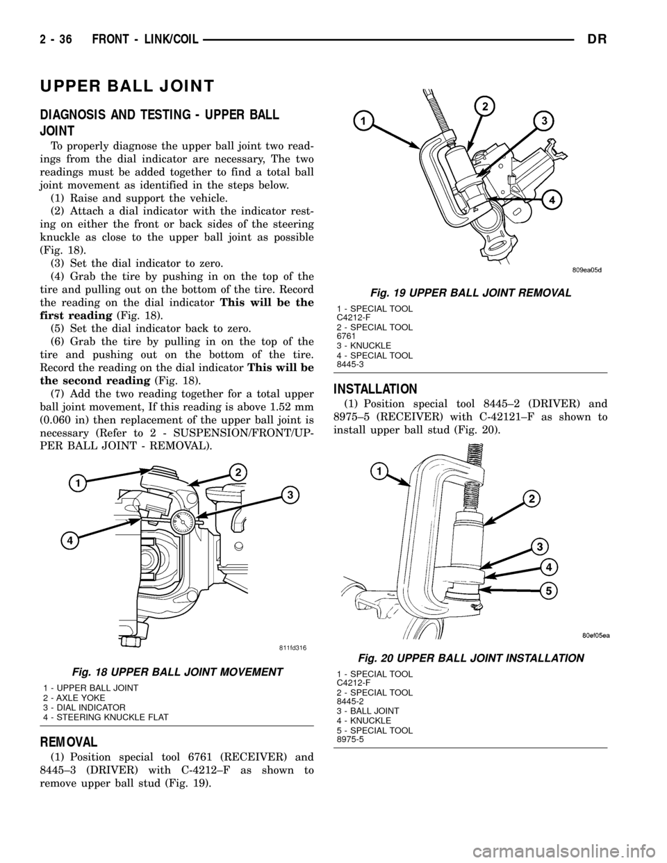
To properly diagnose the upper ball joint two read-
ings from the dial indicator are necessary, The two
readings must be added together to find a total ball
joint movement as identified in the steps below.
(1) Raise and support the vehicle.
(2) Attach a dial indicator with the indicator rest-
ing on either the front or back sides of the steering
knuckle as close to the upper ball joint as possible
(Fig. 18).
(3) Set the dial indicator to zero.
(4) Grab the tire by pushing in on the top of the
tire and pulling out on the bottom of the tire. Record
the reading on the dial indicatorThis will be the
first reading(Fig. 18).
(5) Set the dial indicator back to zero.
(6) Grab the tire by pulling in on the top of the
tire and pushing out on the bottom of the tire.
Record the reading on the dial indicatorThis will be
the second reading(Fig. 18).
(7) Add the two reading together for a total upper
ball joint movement, If this reading is above 1.52 mm
(0.060 in) then replacement of the upper ball joint is
necessary (Refer to 2 - SUSPENSION/FRONT/UP-
PER BALL JOINT - REMOVAL).
REMOVAL
(1) Position special tool 6761 (RECEIVER) and
8445±3 (DRIVER) with C-4212±F as shown to
remove upper ball stud (Fig. 19).
INSTALLATION
(1) Position special tool 8445±2 (DRIVER) and
8975±5 (RECEIVER) with C-42121±F as shown to
install upper ball stud (Fig. 20).
Fig. 18 UPPER BALL JOINT MOVEMENT
1 - UPPER BALL JOINT
2 - AXLE YOKE
3 - DIAL INDICATOR
4 - STEERING KNUCKLE FLAT
Fig. 19 UPPER BALL JOINT REMOVAL
1 - SPECIAL TOOL
C4212-F
2 - SPECIAL TOOL
6761
3 - KNUCKLE
4 - SPECIAL TOOL
8445-3
Fig. 20 UPPER BALL JOINT INSTALLATION
1 - SPECIAL TOOL
C4212-F
2 - SPECIAL TOOL
8445-2
3 - BALL JOINT
4 - KNUCKLE
5 - SPECIAL TOOL
8975-5
2 - 36 FRONT - LINK/COILDR
Page 72 of 2627

KNUCKLE
REMOVAL
(1) Remove the hub bearing (Refer to 2 - SUSPEN-
SION/FRONT/HUB / BEARING - REMOVAL).
(2) Remove tie-rod or drag link end from the steer-
ing knuckle arm.
(3) Remove the ABS sensor wire and bracket from
knuckle. Refer to Brakes, for proper procedures.
(4) Remove the cotter pin from the upper ball stud
nut. Remove the upper and lower ball stud nuts.
(5) Strike the steering knuckle with a brass ham-
mer to loosen.
(6) Remove knuckle from axle tube yokes.
INSTALLATION
(1) Position the steering knuckle on the ball studs.
(2) Install and tighten lower ball stud nut to 47
N´m (35 ft. lbs.) torque. Do not install cotter pin at
this time.
(3) Install and tighten upper ball stud nut to 94
N´m (70 ft. lbs.) torque. Advance nut to next slot to
line up hole and install new cotter pin.
(4) Retorque lower ball stud nut to 190±217 N´m
(140±160 ft. lbs.) torque. Advance nut to next slot to
line up hole and install new cotter pin.
(5) Install the hub bearing (Refer to 2 - SUSPEN-
SION/FRONT/HUB / BEARING - INSTALLATION).
(6) Install tie-rod or drag link end onto the steer-
ing knuckle arm.
(7) Install the ABS sensor wire and bracket to the
knuckle. Refer to Brakes, for proper procedure.
UPPER SUSPENSION ARM
REMOVAL
REMOVAL - LEFT
(1) Raise and support the vehicle.
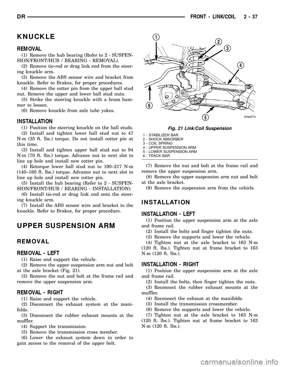
(2) Remove the upper suspension arm nut and bolt
at the axle bracket (Fig. 21).
(3) Remove the nut and bolt at the frame rail and
remove the upper suspension arm.
REMOVAL - RIGHT
(1) Raise and support the vehicle.
(2) Disconnect the exhaust system at the mani-
folds.
(3) Disconnect the rubber exhaust mounts at the
muffler.
(4) Support the transmission.
(5) Remove the transmission cross member.
(6) Lower the exhaust system down in order to
gain access to the removal of the upper bolt.(7) Remove the nut and bolt at the frame rail and
remove the upper suspension arm.
(8) Remove the upper suspension arm nut and bolt
at the axle bracket.
(9) Remove the suspension arm from the vehicle.
INSTALLATION
INSTALLATION - LEFT
(1) Position the upper suspension arm at the axle
and frame rail.
(2) Install the bolts and finger tighten the nuts.
(3) Remove the supports and lower the vehicle.
(4) Tighten nut at the axle bracket to 163 N´m
(120 ft. lbs.). Tighten nut at frame bracket to 163
N´m (120 ft. lbs.).
INSTALLATION - RIGHT
(1) Position the upper suspension arm at the axle
and frame rail.
(2) Install the bolts, then finger tighten the nuts.
(3) Reconnect the rubber exhaust mounts at the
muffler.
(4) Reconnect the exhaust at the manifolds.
(5) Install the transmission crossmember.
(6) Remove the supports and lower the vehicle.
(7) Tighten nut at the axle bracket to 163 N´m
(120 ft. lbs.). Tighten nut at frame bracket to 163
N´m (120 ft. lbs.).
Fig. 21 Link/Coil Suspension
1 - STABILIZER BAR
2 - SHOCK ABSORBER
3 - COIL SPRING
4 - UPPER SUSPENSION ARM
5 - LOWER SUSPENSION ARM
6 - TRACK BAR
DRFRONT - LINK/COIL 2 - 37