1998 DODGE RAM 1500 Power seats
[x] Cancel search: Power seatsPage 1336 of 2627
(9) Install the left side secondary chain guide
(Refer to 9 - ENGINE/VALVE TIMING/TIMING
BELT/CHAIN AND SPROCKETS - INSTALLA-
TION).
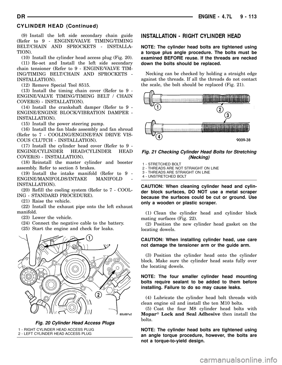
(10) Install the cylinder head access plug (Fig. 20).
(11) Re-set and Install the left side secondary
chain tensioner (Refer to 9 - ENGINE/VALVE TIM-
ING/TIMING BELT/CHAIN AND SPROCKETS -
INSTALLATION).
(12) Remove Special Tool 8515.
(13) Install the timing chain cover (Refer to 9 -
ENGINE/VALVE TIMING/TIMING BELT / CHAIN
COVER(S) - INSTALLATION).
(14) Install the crankshaft damper (Refer to 9 -
ENGINE/ENGINE BLOCK/VIBRATION DAMPER -
INSTALLATION).
(15) Install the power steering pump.
(16) Install the fan blade assembly and fan shroud
(Refer to 7 - COOLING/ENGINE/FAN DRIVE VIS-
COUS CLUTCH - INSTALLATION).
(17) Install the cylinder head cover (Refer to 9 -
ENGINE/CYLINDER HEAD/CYLINDER HEAD
COVER(S) - INSTALLATION).
(18) Reinstall the master cylinder and booster
assembly. Refer to section 5 brakes.
(19) Install the intake manifold (Refer to 9 -
ENGINE/MANIFOLDS/INTAKE MANIFOLD -
INSTALLATION).
(20) Refill the cooling system (Refer to 7 - COOL-
ING - STANDARD PROCEDURE).
(21) Raise the vehicle.
(22) Install the exhaust pipe onto the left exhaust
manifold.
(23) Lower the vehicle.
(24) Connect the negative cable to the battery.
(25) Start the engine and check for leaks.INSTALLATION - RIGHT CYLINDER HEAD
NOTE: The cylinder head bolts are tightened using
a torque plus angle procedure. The bolts must be
examined BEFORE reuse. If the threads are necked
down the bolts should be replaced.
Necking can be checked by holding a straight edge
against the threads. If all the threads do not contact
the scale, the bolt should be replaced (Fig. 21).
CAUTION: When cleaning cylinder head and cylin-
der block surfaces, DO NOT use a metal scraper
because the surfaces could be cut or ground. Use
only a wooden or plastic scraper.
(1) Clean the cylinder head and cylinder block
mating surfaces (Fig. 22).
(2) Position the new cylinder head gasket on the
locating dowels.
CAUTION: When installing cylinder head, use care
not damage the tensioner arm or the guide arm.
(3) Position the cylinder head onto the cylinder
block. Make sure the cylinder head seats fully over
the locating dowels.
NOTE: The four smaller cylinder head mounting
bolts require sealant to be added to them before
installing. Failure to do so may cause leaks.
(4) Lubricate the cylinder head bolt threads with
clean engine oil and install the ten M10 bolts.
(5) Coat the four M8 cylinder head bolts with
MopartLock and Seal Adhesivethen install the
bolts.
NOTE: The cylinder head bolts are tightened using
an angle torque procedure, however, the bolts are
not a torque-to-yield design.
Fig. 20 Cylinder Head Access Plugs
1 - RIGHT CYLINDER HEAD ACCESS PLUG
2 - LEFT CYLINDER HEAD ACCESS PLUG
Fig. 21 Checking Cylinder Head Bolts for Stretching
(Necking)
1 - STRETCHED BOLT
2 - THREADS ARE NOT STRAIGHT ON LINE
3 - THREADS ARE STRAIGHT ON LINE
4 - UNSTRETCHED BOLT
DRENGINE - 4.7L 9 - 113
CYLINDER HEAD (Continued)
Page 1423 of 2627
þ Loss of engine power
þ Engine misfiring
þ Poor fuel economy
²Possible indications of the cylinder head gasket
leaking between a cylinder and an adjacent water
jacket are:
þ Engine overheating
þ Loss of coolant
þ Excessive steam (white smoke) emitting from
exhaust
þ Coolant foaming
CYLINDER-TO-CYLINDER LEAKAGE TEST
To determine if an engine cylinder head gasket is
leaking between adjacent cylinders, follow the proce-
dures in Cylinder Compression Pressure Test in this
section. An engine cylinder head gasket leaking
between adjacent cylinders will result in approxi-
mately a 50±70% reduction in compression pressure.
CYLINDER-TO-WATER JACKET LEAKAGE TEST
WARNING: USE EXTREME CAUTION WHEN THE
ENGINE IS OPERATING WITH COOLANT PRES-
SURE CAP REMOVED.
VISUAL TEST METHOD
With the engine cool, remove the coolant pressure
cap. Start the engine and allow it to warm up until
thermostat opens.
If a large combustion/compression pressure leak
exists, bubbles will be visible in the coolant.
COOLING SYSTEM TESTER METHOD
WARNING: WITH COOLING SYSTEM TESTER IN
PLACE, PRESSURE WILL BUILD UP FAST. EXCES-
SIVE PRESSURE BUILT UP, BY CONTINUOUS
ENGINE OPERATION, MUST BE RELEASED TO A
SAFE PRESSURE POINT. NEVER PERMIT PRES-
SURE TO EXCEED 138 kPa (20 psi).
Install Cooling System Tester 7700 or equivalent to
pressure cap neck. Start the engine and observe the
tester's pressure gauge. If gauge pulsates with every
power stroke of a cylinder a combustion pressure
leak is evident.
CHEMICAL TEST METHOD
Combustion leaks into the cooling system can also
be checked by using Bloc-Chek Kit C-3685-A or
equivalent. Perform test following the procedures
supplied with the tool kit.
REMOVAL
(1) Disconnect the battery negative cable.
(2) Drain cooling system.
(3) Remove the air cleaner resonator and duct
work.
(4) Remove the generator.
(5) Remove closed crankcase ventilation system.
(6) Disconnect the evaporation control system.
(7) Perform the Fuel System Pressure Release pro-
cedure (Refer to 14 - FUEL SYSTEM/FUEL DELIV-
ERY - STANDARD PROCEDURE). Disconnect the
fuel supply line (Refer to 14 - FUEL SYSTEM/FUEL
DELIVERY/QUICK CONNECT FITTING - STAN-
DARD PROCEDURE).
(8) Disconnect heater hoses.
(9) Remove cylinder head covers and gaskets.
(10) Remove intake manifold and throttle body as
an assembly.
(11) Remove rocker arm assemblies and push rods.
Identify to ensure installation in original locations.
(12) Remove the head bolts from each cylinder
head and remove cylinder heads. Discard the cylin-
der head gasket.
CLEANING
Clean all surfaces of cylinder block and cylinder
heads.
Clean cylinder block front and rear gasket surfaces
using a suitable solvent.
INSPECTION
(1) Inspect the cylinder head for out-of-flatness,
using a straightedge and a feeler gauge. If tolerances
exceed 0.0508 mm (0.002 in.) replace the cylinder
head.
(2) Inspect the valve seats for damage. Service the
valve seats as necessary.
(3) Inspect the valve guides for wear, cracks or
looseness. If either condition exist, replace the cylin-
der head.
(4) Inspect pushrods. Replace worn or bent push-
rods.
INSTALLATION
(1) Clean all surfaces of cylinder block and cylin-
der heads.
(2) Clean cylinder block front and rear gasket sur-
faces using a suitable solvent.
CAUTION: The head gaskets are not interchange-
able between left and right sides. They are marked
ªLº and ªRº to indicate left and right sides.
(3) Position new cylinder head gaskets onto the
cylinder block.
9 - 200 ENGINE - 5.7LDR
CYLINDER HEAD (Continued)
Page 1425 of 2627
INTAKE/EXHAUST VALVES &
SEATS
DESCRIPTION
DESCRIPTION - VALVE GUIDES
The valve guides are made of powered metal and
are pressed into the cylinder head. The guides are
not replaceable or serviceable, and valve guide ream-
ing is not recommended. If the guides are worn
beyond acceptable limits, replace the cylinder heads.
DESCRIPTION
Both the intake and exhaust valves are made of
steel. The intake valve is 50.93 mm (2.00 inches) in
diameter and the exhaust valve is 39.53 mm (1.55
inches) in diameter. All valves use three bead lock
keepers to retain the springs and promote valve rota-
tion.
STANDARD PROCEDURE - REFACING
NOTE: Valve seats that are worn or burned can be
reworked, provided that correct angle and seat
width are maintained. Otherwise the cylinder head
must be replaced.
NOTE: When refacing valves and valve seats, it is
important that the correct size valve guide pilot be
used for reseating stones. A true and complete sur-
face must be obtained.
(1) Using a suitable dial indicator measure the
center of the valve seat Total run out must not
exceed 0.051 mm (0.002 in).
(2) Apply a small amount of Prussian blue to the
valve seat, insert the valve into the cylinder head,
while applying light pressure on the valve rotate the
valve. Remove the valve and examine the valve face.
If the blue is transferred below the top edge of the
valve face, lower the valve seat using a 15 degree
stone. If the blue is transferred to the bottom edge of
the valve face, raise the valve seat using a 65 degree
stone.
(3) When the seat is properly positioned the width
of the intake seat must be 1.018 - 1.62 mm (0.0464 -
0.0637 in.) and the exhaust seat must be 1.48 - 1.92
mm (0.058 - 0.075 in.).
(4) Check the valve spring installed height after
refacing the valve and seat. The installed height for
both intake and exhaust valve springs must not
exceed 46.0 mm (1.81 in.).
VALVE FACE AND VALVE SEAT ANGLE CHART
DESCRIPTION SPECIFICATION
SEAT WIDTH
INTAKE 1.018 - 1.62 mm
(0.0464 - 0.0637 in.)
EXHAUST 1.48 - 1.92 mm
(0.058 - 0.075 in.)
FACE ANGLE
(INT. AND EXT.) 45É - 45
1¤2É
SEAT ANGLE
(INT. AND EXT.) 44
1¤2É - 45É
(5)
The valve seat must maintain an angle of 44.5 ±
45.0 degrees angle.
(6) The valve face must maintain a face angle of
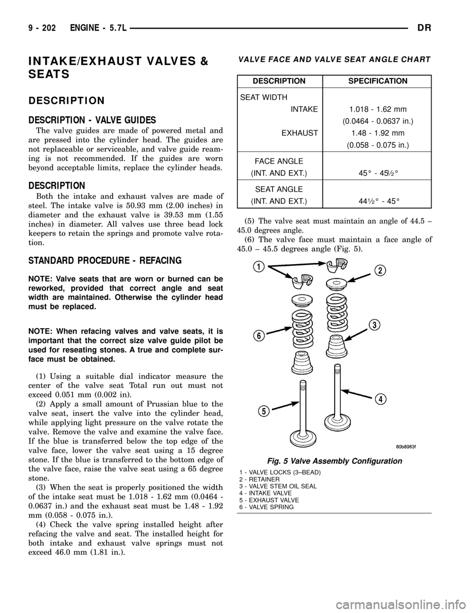
45.0 ± 45.5 degrees angle (Fig. 5).
Fig. 5 Valve Assembly Configuration
1 - VALVE LOCKS (3±BEAD)
2 - RETAINER
3 - VALVE STEM OIL SEAL
4 - INTAKE VALVE
5 - EXHAUST VALVE
6 - VALVE SPRING
9 - 202 ENGINE - 5.7LDR
Page 1460 of 2627
EXCESSIVE WHITE SMOKE
POSSIBLE CAUSE CORRECTION
Air in fuel supply: Possible leak in fuel supply side (between
transfer pump and fuel tank module).(Refer to 14 - FUEL SYSTEM/FUEL DELIVERY/FUEL
TRANSFER PUMP - DIAGNOSIS AND TESTING).
Coolant leaking into combustion chamber. Do pressure test of cooling system (Refer to 7 - COOLING -
DIAGNOSIS AND TESTING).
Diagnostic Trouble Codes (DTC's) active or multiple,
intermittent DTC's.Refer to Powertrain Diagnostic Procedures Information.
In very cold ambient temperatures, engine block heater is
malfunctioning (if equipped).(Refer to 7 - COOLING/ENGINE/ENGINE BLOCK HEATER -
REMOVAL).
Engine coolant temperature sensor malfunctioning. A DTC should have been set. Refer to Powertrain Diagnostic
Procedures Information. Also check thermostat operation
(Refer to 7 - COOLING/ENGINE/ENGINE COOLANT
THERMOSTAT - DIAGNOSIS AND TESTING).
Engine Control Module (ECM) not calibrated or has incorrect
calibration.A DTC should have been set. Refer to Powertrain Diagnostic
Procedures Information.
Fuel filter plugged. Refer to Powertrain Diagnostic Manual for fuel system testing.
Fuel grade not correct or fuel quality is poor. Temporarily change fuel brands and note condition. Change
brand if necessary.
Fuel heater element or fuel heater temperature sensor
malfunctioning. This will cause wax type build-up in fuel filter.Refer to Fuel Heater Testing (Refer to 14 - FUEL SYSTEM/
FUEL DELIVERY/FUEL HEATER - DIAGNOSIS AND
TESTING).
Fuel injector malfunctioning. A DTC should have been set. Perform9Cylinder cutout Test9
using DRB scan tool to isolate individual cylinders. Also refer
to Powertrain Diagnostic Procedures Information and, (Refer
to 14 - FUEL SYSTEM/FUEL INJECTION/FUEL INJECTOR -
DIAGNOSIS AND TESTING).
Fuel injector hold-downs loose. Torque to specifications.
Fuel injector protrusion not correct. Check washer (shim) at bottom of fuel injector for correct
thickness. (Refer to 14 - FUEL SYSTEM/FUEL INJECTION/
FUEL INJECTOR - INSTALLATION)
Fuel injection pump malfunctioning. A DTC should have been set. Refer to Powertrain Diagnostic
Procedures Information.
Fuel supply side restriction to transfer pump. Refer to Powertrain Diagnostic Manual for fuel system testing.
Fuel transfer (lift) pump malfunctioning. A DTC may have been set. Refer to Powertrain Diagnostic
Procedures Information.
Intake/Exhaust valve adjustments not correct (too tight). (Refer to 9 - ENGINE/CYLINDER HEAD/INTAKE/EXHAUST
VALVES & SEATS - STANDARD PROCEDURE).
Intake manifold air temperature sensor malfunctioning. A DTC should have been set. Refer to Powertrain Diagnostic
Procedures Information.
Intake manifold heater circuit not functioning correctly in cold
weather.A DTC should have been set. Refer to Powertrain Diagnostic
Procedures Information. Also check heater elements for
correct operation.
Intake manifold heater elements not functioning correctly in
cold weather.A DTC should have been set if heater elements are
malfunctioning. Refer to Powertrain Diagnostic Procedures
Information.
Internal engine damage (scuffed cylinder). Analyze engine oil and inspect oil filter to locate area of
probable damage.
Restriction in fuel supply side of fuel system. Refer to Powertrain Diagnostic Manual for fuel system testing.
DRENGINE 5.9L DIESEL 9 - 237
ENGINE 5.9L DIESEL (Continued)
Page 1495 of 2627
(6) Remove the wooden dowel rods and rubber
bands from the tappets.
(7) Lubricate the push rods with engine oil and
install in their original location.Verify that they
are seated in the tappets.
(8) Lubricate the valve tips with engine oil and
install the crossheads in their original locations.
(9) Lubricate the crossheads and push rod sockets
with engine oil and install the rocker arms and ped-
estals in their original locations. Tighten bolts to 36
N´m (27 ft. lbs.) torque.
(10)Verify valve lash adjustment (Refer to 9 -
ENGINE/CYLINDER HEAD/INTAKE/EXHAUST
VALVES & SEATS - STANDARD PROCEDURE).
(11) Install the cylinder head cover and reusable
gasket (Refer to 9 - ENGINE/CYLINDER HEAD/
CYLINDER HEAD COVER(S) - INSTALLATION).
(12) Install gear housing cover (Refer to 9 -
ENGINE/VALVE TIMING/GEAR HOUSING COVER
- INSTALLATION). Install front crankshaft dust
seal.
(13) Install the crankshaft damper with the speed
indicator ring (Refer to 9 - ENGINE/ENGINE
BLOCK/VIBRATION DAMPER - INSTALLATION).
(14) Install the fan support/hub assembly Refer to
(Refer to 7 - COOLING/ENGINE/RADIATOR FAN -
INSTALLATION).
(15) Install the power steering pump.
(16) Install accessory drive belt tensioner. Torque
bolt to 43 Nm (32 ft. lbs.).
(17) Install the accessory drive belt (Refer to 7 -
COOLING/ACCESSORY DRIVE/DRIVE BELTS -
INSTALLATION).
(18) Install the charge air cooler (with a/c con-
denser and auxiliary transmission oil cooler, if
equipped) and tighten the mounting bolts to 2 N´m
(17 in. lbs.) torque.
(19) Connect charge air cooler inlet and outlet
pipes. Tighten clamps to 11 N´m (95 in. lbs.) torque.
(20) Install the radiator upper support panel.
(21) Close radiator petcock and lower the radiator
into the engine compartment. Tighten the mounting
bolts to 11 N´m (95 in. lbs.) torque.
(22) Raise vehicle on hoist.
(23) Connect radiator lower hose and install
clamp.
(24) Connect transmission auxiliary oil cooler lines
(if equipped).
(25) Lower vehicle.
(26) Install the fan shroud and tighten the mount-
ing screws to 6 N´m (50 in. lbs.) torque.
(27) Install the electronically controlled viscous
fan/drive assembly. Connect harness connector.(Refer
to 7 - COOLING/ENGINE/RADIATOR FAN -
INSTALLATION).(28) Install the coolant recovery and windshield
washer fluid reservoirs to the fan shroud.
(29) Connect the coolant recovery hose to the radi-
ator filler neck.
(30) Add engine coolant (Refer to 7 - COOLING -
STANDARD PROCEDURE).
(31) Charge A/C system with refrigerant (if A/C
equipped) (Refer to 24 - HEATING & AIR CONDI-
TIONING/PLUMBING - STANDARD PROCEDURE).
(32) Connect the battery negative cables.
(33) Start engine and check for engine oil and cool-
ant leaks.
CONNECTING ROD BEARINGS
STANDARD PROCEDURE - CONNECTING ROD
BEARING AND CRANKSHAFT JOURNAL
CLEARANCE
(1) Measure the connecting rod bore with bearings
removedand the bolts tightened to 100 N´m (73 ft.
lbs.) torque..
(2) Measure the connecting rod bore with the bear-
ingsinstalledand the bolts tightened to 100 N´m
(73 ft. lbs.) torque.
Measure within 20É arc from each side of the part-
ing line. Also measure 90É from parting line.
Record the smallest and largest diameter.
Measure the diameter of the rod journal at the
location shown (Fig. 63). Calculate the average diam-
eter for each side of the journal.
Determine minimum bearing clearance by calculat-
ing the differance between the smallest connecting
rod bore diameter with the bearing installed and the
average diameter for each side of the crankshaft jour-
nal.
Determine the maximum bearing clearance by cal-
culating the difference between the largest connect-
ing rod bore diameter and the average diameter with
the bearing installed for each side of the crankshaft
journal.
DESCRIPTION MEASUREMENT
CONNECTING ROD
BORE, BEARINGS
REMOVEDMIN. 72.99 mm (2.874
in.)
MAX. 73.01 mm (2.875
in.)
CONNECTING ROD
BORE, BEARINGS
INSTALLEDMIN. 69.05 mm (2.719
in.)
MAX. 69.10 mm (2.720
in.)
9 - 272 ENGINE 5.9L DIESELDR
CAMSHAFT & BEARINGS (IN BLOCK) (Continued)
Page 1519 of 2627
(8) Measure the clearance of the gerotor planetary
to the body bore (Fig. 114). Maximum clearance is
0.381 mm (0.015 inch). If the oil pump is out of lim-
its, replace the pump.
(9) Measure the gears backlash (Fig. 115). The lim-
its of a used pump is 0.15- 0.25 mm (0.006-0.010
inch). If the backlash is out of limits, replace the oil
pump.
(10) Install the back plate.
INSTALLATION
(1) Lubricate the pump with clean engine oil. Fill-
ing the pump with clean engine oil during installa-
tion will help to prime the pump at engine start up.
(2) Install the pump (Fig. 110). Verify the idler
gear pin is installed in the locating bore in the cylin-
der block. Tighten the oil pump mounting bolts in
two steps, in the sequence shown in (Fig. 116).
²Step 1ÐTighten to 8 N´m (71 in. lbs.) torque.
²Step 2ÐTighten to 24 N´m (18 ft. lbs.) torque.
(3) The back plate on the pump seats against the
bottom of the bore in the cylinder block. When the
pump is correctly installed, the flange on the pump
will not touch the cylinder block.(4) Measure the idler gear to pump drive gear
backlash and the idler gear to crankshaft gear back-
lash (Fig. 117). The backlash should be 0.15- 0.25
mm (0.006-0.010 inch). If the backlash is out of lim-
its, replace the oil pump.
(5) If the adjoining gear moves when you measure
the backlash, the reading will be incorrect.
(6) Apply a bead of MopartSilicone Rubber Adhe-
sive Sealant or equivalent to the gear housing cover
sealing surface.
(7) Install the gear housing cover (Refer to 9 -
ENGINE/VALVE TIMING/GEAR HOUSING COVER
- INSTALLATION).
(8) Install the vibration damper (Refer to 9 -
ENGINE/ENGINE BLOCK/VIBRATION DAMPER -
INSTALLATION) and speed indicator ring.
(9) Install the fan support/hub assembly Refer to
(Refer to 7 - COOLING/ENGINE/RADIATOR FAN -
INSTALLATION)
(10) Install power steering pump.
(11) Install accessory drive belt tensioner. Torque
bolt to 43 N´m (32 ft. lbs.).
(12) Install the accessory drive belt (Refer to 7 -
COOLING/ACCESSORY DRIVE/DRIVE BELTS -
INSTALLATION).
Fig. 114 Measuring Gerotor Planetary to Body Bore
Clearance
1 - BODY BORE
2 - GEROTOR PLANETARY
Fig. 115 Measure Gear Backlash
1 - OIL PUMP DRIVE GEAR
2 - IDLER GEAR
3 - BACKLASH
4 - BACKLASH
Fig. 116 Oil Pump Mounting Bolt Torque Sequence
Fig. 117 Idler Gear to Pump Drive Gear and
Crankshaft Gear Backlash
9 - 296 ENGINE 5.9L DIESELDR
OIL PUMP (Continued)
Page 1686 of 2627
(4) Clean exposed end of pitman shaft and housing
with a wire brush.
(5) Rotate the stub shaft with a 12 point socket
from stop to stop and count the number of turns (Fig.
23).
(6) Center the stub shaft by rotating it from the
stop 1/2 of the total amount of turns (Fig. 23).
(7) Remove the pitman shaft cover bolts.
NOTE: The pitman shaft will not clear the housing if
it is not centered.
(8)
Remove the pitman shaft from the gear (Fig. 24).
(9) Remove the cover if needed by loosing the
adjuster nut, Then removing the cover from the pit-
man shaft.
INSTALLATION
INSTALLATION - GAS
(1) Coat the seal withpower steering fluid.
(2) Install pitman shaft into the steering gear until
it fully seats into the bearing.
(3) Install the new cover bolts and tighten to 68
N´m (50 ft. lbs.).
(4) Perform over-center meshload adjustment,
(Refer to 19 - STEERING/GEAR - ADJUSTMENTS).
(5) Install the pitman arm (Refer to 19 - STEER-
ING/LINKAGE/PITMAN ARM - INSTALLATION).
(6) Perform a wheel alignment (Refer to 2 - SUS-
PENSION/WHEEL ALIGNMENT - STANDARD
PROCEDURE).
INSTALLATION - DIESEL
(1) Coat the seal withpower steering fluid.
(2) Install the pitman shaft into the steering gear
until it fully seats into the bearing.
(3) Install the new cover bolts and tighten to 68
N´m (50 ft. lbs.).
(4) Perform over-center meshload adjustment
(Refer to 19 - STEERING/GEAR - ADJUSTMENTS).
(5) Install the steering gear (Refer to 19 - STEER-
ING/GEAR - INSTALLATION).
(6) Install the pitman arm (Refer to 19 - STEER-
ING/LINKAGE/PITMAN ARM - INSTALLATION).
(7) Perform a wheel alignment (Refer to 2 - SUS-
PENSION/WHEEL ALIGNMENT - STANDARD
PROCEDURE).
Fig. 22 PITMAN SHAFT
1 - PITMAN SHAFT
2 - O-RING SEAL
3 - COVER
4 - ADJUSTING NUT
Fig. 23 CENTERING STEERING GEAR
1 - STEERING GEAR
2 - 12 POINT SOCKET
3 - RATCHET
4 - INPUT SHAFT
Fig. 24 PITMAN SHAFT
1 - PITMAN SHAFT
2 - O-RING SEAL
3 - COVER
4 - ADJUSTING NUT
DRGEAR - LINK/COIL 19 - 31
PITMAN SHAFT (Continued)
Page 2370 of 2627
SEATS
TABLE OF CONTENTS
page page
CENTER SEAT
REMOVAL.............................75
INSTALLATION.........................76
CENTER ARMREST / SEAT BACK
REMOVAL.............................76
INSTALLATION.........................77
CENTER SEAT BACK INERTIA HINGE COVER
REMOVAL.............................77
INSTALLATION.........................77
CENTER SEAT BACK HINGE
REMOVAL.............................78
INSTALLATION.........................79
CENTER SEAT BACK LID
REMOVAL.............................79
INSTALLATION.........................79
CENTER SEAT CUSHION
REMOVAL.............................79
INSTALLATION.........................79
CENTER SEAT CUSHION COVER
REMOVAL.............................79
INSTALLATION.........................79
UNDER SEAT STORAGE BIN LID
REMOVAL.............................80
INSTALLATION.........................80
UNDER SEAT STORAGE BIN
REMOVAL.............................80
INSTALLATION.........................80
UNDER SEAT STORAGE BIN COVERING
REMOVAL.............................80
INSTALLATION.........................80
UNDER SEAT STORAGE BIN LATCH
REMOVAL.............................80
INSTALLATION.........................80
HEADREST
REMOVAL.............................80
INSTALLATION.........................80
HEADREST SLEEVE
REMOVAL.............................81INSTALLATION.........................81
SEAT - FRONT
REMOVAL.............................81
INSTALLATION.........................81
LUMBAR SUPPORT HANDLE/BEZEL
REMOVAL.............................82
INSTALLATION.........................82
SEAT BACK CUSHION / COVER - FRONT
REMOVAL.............................82
INSTALLATION.........................82
SEAT CUSHION / COVER - FRONT
REMOVAL.............................83
INSTALLATION.........................83
SEAT TRACK
REMOVAL.............................83
INSTALLATION.........................83
SEAT - REAR
REMOVAL.............................83
INSTALLATION.........................83
SEAT BACK - REAR
REMOVAL.............................83
INSTALLATION.........................83
SEAT BACK CUSHION / COVER - REAR
REMOVAL.............................84
INSTALLATION.........................84
SEAT CUSHION / COVER - REAR
REMOVAL.............................84
INSTALLATION.........................84
SEAT CUSHION FRAME - REAR
REMOVAL.............................85
INSTALLATION.........................85
SEAT BACK REAR - FOOTMANS LOOP
BRACKETS
REMOVAL.............................85
INSTALLATION.........................85
CENTER SEAT
REMOVAL
NOTE: Do not reuse the seat fasteners, always
replace with new ones.
(1) Remove and discard the front bolts. (Fig. 1)(2) Position the seats forward, remove the rear
bolts and discard.
(3) Disconnect the 12v power supply electrical con-
nector, if equipped. (Fig. 2)
(4) Fold the seat backs forward and roll the seat
assembly back in the vehicle.
(5) Remove the nuts attaching the center seat to
the drivers seat and the passenger seat and discard.
(Fig. 3)
DRSEATS 23 - 75