1998 DODGE RAM 1500 Door wiring harness
[x] Cancel search: Door wiring harnessPage 2306 of 2627
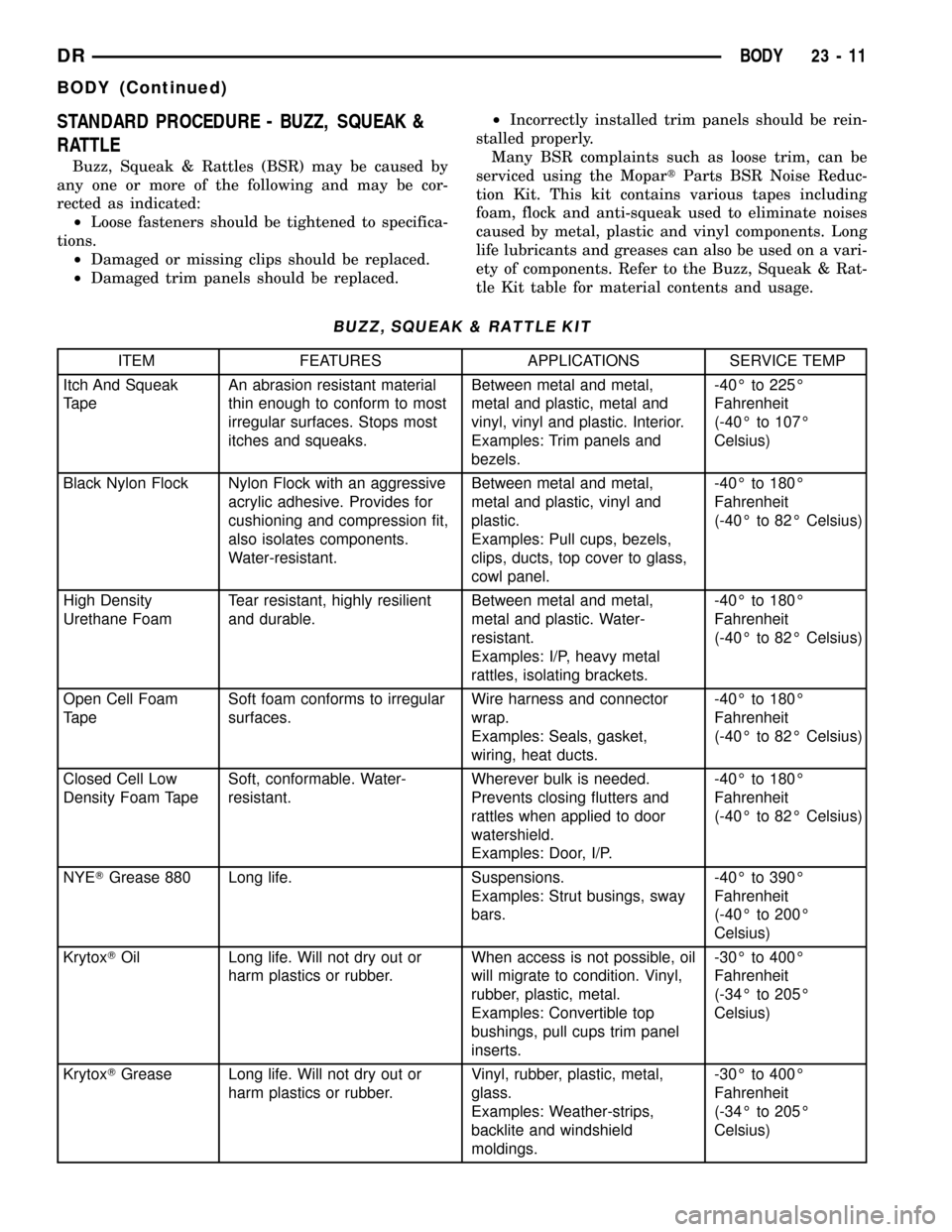
STANDARD PROCEDURE - BUZZ, SQUEAK &
RATTLE
Buzz, Squeak & Rattles (BSR) may be caused by
any one or more of the following and may be cor-
rected as indicated:
²Loose fasteners should be tightened to specifica-
tions.
²Damaged or missing clips should be replaced.
²Damaged trim panels should be replaced.²Incorrectly installed trim panels should be rein-
stalled properly.
Many BSR complaints such as loose trim, can be
serviced using the MopartParts BSR Noise Reduc-
tion Kit. This kit contains various tapes including
foam, flock and anti-squeak used to eliminate noises
caused by metal, plastic and vinyl components. Long
life lubricants and greases can also be used on a vari-
ety of components. Refer to the Buzz, Squeak & Rat-
tle Kit table for material contents and usage.
BUZZ, SQUEAK & RATTLE KIT
ITEM FEATURES APPLICATIONS SERVICE TEMP
Itch And Squeak
TapeAn abrasion resistant material
thin enough to conform to most
irregular surfaces. Stops most
itches and squeaks.Between metal and metal,
metal and plastic, metal and
vinyl, vinyl and plastic. Interior.
Examples: Trim panels and
bezels.-40É to 225É
Fahrenheit
(-40É to 107É
Celsius)
Black Nylon Flock Nylon Flock with an aggressive
acrylic adhesive. Provides for
cushioning and compression fit,
also isolates components.
Water-resistant.Between metal and metal,
metal and plastic, vinyl and
plastic.
Examples: Pull cups, bezels,
clips, ducts, top cover to glass,
cowl panel.-40É to 180É
Fahrenheit
(-40É to 82É Celsius)
High Density
Urethane FoamTear resistant, highly resilient
and durable.Between metal and metal,
metal and plastic. Water-
resistant.
Examples: I/P, heavy metal
rattles, isolating brackets.-40É to 180É
Fahrenheit
(-40É to 82É Celsius)
Open Cell Foam
TapeSoft foam conforms to irregular
surfaces.Wire harness and connector
wrap.
Examples: Seals, gasket,
wiring, heat ducts.-40É to 180É
Fahrenheit
(-40É to 82É Celsius)
Closed Cell Low
Density Foam TapeSoft, conformable. Water-
resistant.Wherever bulk is needed.
Prevents closing flutters and
rattles when applied to door
watershield.
Examples: Door, I/P.-40É to 180É
Fahrenheit
(-40É to 82É Celsius)
NYETGrease 880 Long life. Suspensions.
Examples: Strut busings, sway
bars.-40É to 390É
Fahrenheit
(-40É to 200É
Celsius)
KrytoxTOil Long life. Will not dry out or
harm plastics or rubber.When access is not possible, oil
will migrate to condition. Vinyl,
rubber, plastic, metal.
Examples: Convertible top
bushings, pull cups trim panel
inserts.-30É to 400É
Fahrenheit
(-34É to 205É
Celsius)
KrytoxTGrease Long life. Will not dry out or
harm plastics or rubber.Vinyl, rubber, plastic, metal,
glass.
Examples: Weather-strips,
backlite and windshield
moldings.-30É to 400É
Fahrenheit
(-34É to 205É
Celsius)
DRBODY 23 - 11
BODY (Continued)
Page 2507 of 2627
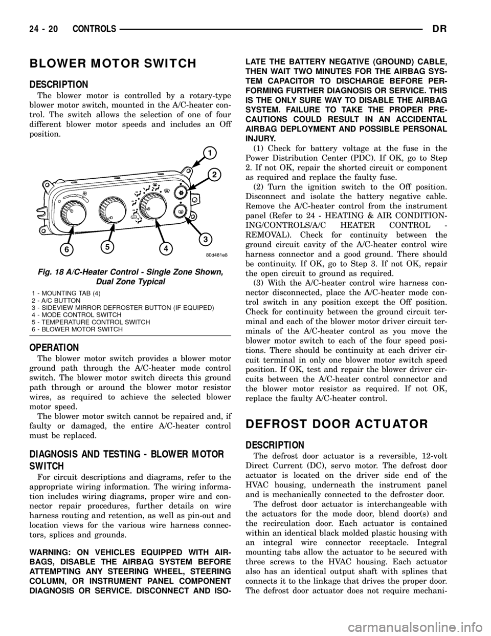
BLOWER MOTOR SWITCH
DESCRIPTION
The blower motor is controlled by a rotary-type
blower motor switch, mounted in the A/C-heater con-
trol. The switch allows the selection of one of four
different blower motor speeds and includes an Off
position.
OPERATION
The blower motor switch provides a blower motor
ground path through the A/C-heater mode control
switch. The blower motor switch directs this ground
path through or around the blower motor resistor
wires, as required to achieve the selected blower
motor speed.
The blower motor switch cannot be repaired and, if
faulty or damaged, the entire A/C-heater control
must be replaced.
DIAGNOSIS AND TESTING - BLOWER MOTOR
SWITCH
For circuit descriptions and diagrams, refer to the
appropriate wiring information. The wiring informa-
tion includes wiring diagrams, proper wire and con-
nector repair procedures, further details on wire
harness routing and retention, as well as pin-out and
location views for the various wire harness connec-
tors, splices and grounds.
WARNING: ON VEHICLES EQUIPPED WITH AIR-
BAGS, DISABLE THE AIRBAG SYSTEM BEFORE
ATTEMPTING ANY STEERING WHEEL, STEERING
COLUMN, OR INSTRUMENT PANEL COMPONENT
DIAGNOSIS OR SERVICE. DISCONNECT AND ISO-LATE THE BATTERY NEGATIVE (GROUND) CABLE,
THEN WAIT TWO MINUTES FOR THE AIRBAG SYS-
TEM CAPACITOR TO DISCHARGE BEFORE PER-
FORMING FURTHER DIAGNOSIS OR SERVICE. THIS
IS THE ONLY SURE WAY TO DISABLE THE AIRBAG
SYSTEM. FAILURE TO TAKE THE PROPER PRE-
CAUTIONS COULD RESULT IN AN ACCIDENTAL
AIRBAG DEPLOYMENT AND POSSIBLE PERSONAL
INJURY.
(1) Check for battery voltage at the fuse in the
Power Distribution Center (PDC). If OK, go to Step
2. If not OK, repair the shorted circuit or component
as required and replace the faulty fuse.
(2) Turn the ignition switch to the Off position.
Disconnect and isolate the battery negative cable.
Remove the A/C-heater control from the instrument
panel (Refer to 24 - HEATING & AIR CONDITION-
ING/CONTROLS/A/C HEATER CONTROL -
REMOVAL). Check for continuity between the
ground circuit cavity of the A/C-heater control wire
harness connector and a good ground. There should
be continuity. If OK, go to Step 3. If not OK, repair
the open circuit to ground as required.
(3) With the A/C-heater control wire harness con-
nector disconnected, place the A/C-heater mode con-
trol switch in any position except the Off position.
Check for continuity between the ground circuit ter-
minal and each of the blower motor driver circuit ter-
minals of the A/C-heater control as you move the
blower motor switch to each of the four speed posi-
tions. There should be continuity at each driver cir-
cuit terminal in only one blower motor switch speed
position. If OK, test and repair the blower driver cir-
cuits between the A/C-heater control connector and
the blower motor resistor as required. If not OK,
replace the faulty A/C-heater control.
DEFROST DOOR ACTUATOR
DESCRIPTION
The defrost door actuator is a reversible, 12-volt
Direct Current (DC), servo motor. The defrost door
actuator is located on the driver side end of the
HVAC housing, underneath the instrument panel
and is mechanically connected to the defroster door.
The defrost door actuator is interchangeable with
the actuators for the mode door, blend door(s) and
the recirculation door. Each actuator is contained
within an identical black molded plastic housing with
an integral wire connector receptacle. Integral
mounting tabs allow the actuator to be secured with
three screws to the HVAC housing. Each actuator
also has an identical output shaft with splines that
connects it to the linkage that drives the proper door.
The defrost door actuator does not require mechani-
Fig. 18 A/C-Heater Control - Single Zone Shown,
Dual Zone Typical
1 - MOUNTING TAB (4)
2 - A/C BUTTON
3 - SIDEVIEW MIRROR DEFROSTER BUTTON (IF EQUIPED)
4 - MODE CONTROL SWITCH
5 - TEMPERATURE CONTROL SWITCH
6 - BLOWER MOTOR SWITCH
24 - 20 CONTROLSDR
Page 2515 of 2627
(5) Install the HVAC housing (Refer to 24 - HEAT-
ING & AIR CONDITIONING/DISTRIBUTION/HVAC
HOUSING - INSTALLATION)
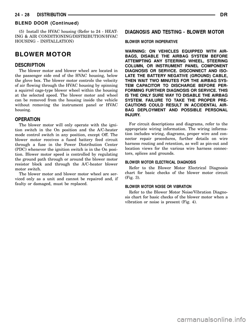
BLOWER MOTOR
DESCRIPTION
The blower motor and blower wheel are located in
the passenger side end of the HVAC housing, below
the glove box. The blower motor controls the velocity
of air flowing through the HVAC housing by spinning
a squirrel cage-type blower wheel within the housing
at the selected speed. The blower motor and wheel
can be removed from the housing inside the vehicle
without removing the instrument panel or HVAC
housing.
OPERATION
The blower motor will only operate with the igni-
tion switch in the On position and the A/C-heater
mode control switch in any position, except Off. The
blower motor receives a fused battery feed circuit
through a fuse in the Power Distribution Center
(PDC) whenever the ignition switch is in the On posi-
tion. Blower motor speed is controlled by regulating
the ground path through or around the blower motor
resistor block and through the A/C-heater blower
motor switch.
The blower motor and blower motor wheel are ser-
viced only as a unit and cannot be repaired and, if
faulty or damaged, must be replaced.
DIAGNOSIS AND TESTING - BLOWER MOTOR
BLOWER MOTOR INOPERATIVE
WARNING: ON VEHICLES EQUIPPED WITH AIR-
BAGS, DISABLE THE AIRBAG SYSTEM BEFORE
ATTEMPTING ANY STEERING WHEEL, STEERING
COLUMN, OR INSTRUMENT PANEL COMPONENT
DIAGNOSIS OR SERVICE. DISCONNECT AND ISO-
LATE THE BATTERY NEGATIVE (GROUND) CABLE,
THEN WAIT TWO MINUTES FOR THE AIRBAG SYS-
TEM CAPACITOR TO DISCHARGE BEFORE PER-
FORMING FURTHER DIAGNOSIS OR SERVICE. THIS
IS THE ONLY SURE WAY TO DISABLE THE AIRBAG
SYSTEM. FAILURE TO TAKE THE PROPER PRE-
CAUTIONS COULD RESULT IN ACCIDENTAL AIR-
BAG DEPLOYMENT AND POSSIBLE PERSONAL
INJURY.
For circuit descriptions and diagrams, refer to the
appropriate wiring information. The wiring informa-
tion includes wiring, diagrams, proper wire and con-
nector repair procedures, further details on wire
harness routing and retention, as well as pin-out and
location views for the various wire harness connec-
tors, splices and grounds.
BLOWER MOTOR ELECTRICAL DIAGNOSIS
Refer to the Blower Motor Electrical Diagnosis
chart for basic checks of the blower motor circuit
(Fig. 3).
BLOWER MOTOR NOISE OR VIBRATION
Refer to the Blower Motor Noise/Vibration Diagno-
sis chart for basic checks of the blower motor when a
vibration or noise is present (Fig. 4).
24 - 28 DISTRIBUTIONDR
BLEND DOOR (Continued)
Page 2522 of 2627

DISASSEMBLY
(1) Remove the HVAC housing from the vehicle
and place it on the workbench (Refer to 24 - HEAT-
ING & AIR CONDITIONING/DISTRIBUTION/HVAC
HOUSING - REMOVAL).
(2) Disconnect the electrical connectors from the
blower motor, blower motor resistor block, evaporator
temperature sensor and each actuator (Fig. 10).
(3) Remove the HVAC wiring harness from the
HVAC housing.
(4) If necessary, remove the blower motor from
the HVAC housing (Refer to 24 - HEATING & AIR
CONDITIONING/DISTRIBUTION/BLOWER
MOTOR - REMOVAL).
(5) If necessary, remove the blower motor resistor
block from the HVAC housing (Refer to 24 - HEAT-
ING & AIR CONDITIONING/CONTROLS/BLOWER
MOTOR RESISTOR BLOCK - REMOVAL).
(6) Carefully remove the foam seals from the
heater core and evaporator coil tube mounting flange
of the HVAC housing. If the either seal is deformed
or damaged, it must be replaced.
(7) Remove the screws that secure the heater core
in the HVAC housing and carefully remove the
heater core from the housing (Refer to 24 - HEAT-
ING & AIR CONDITIONING/PLUMBING/HEATER
CORE - REMOVAL).(8) Use a screwdriver to pry off the four snap clips
that help secure the upper and lower HVAC housing
halves together.
(9) Remove the screws that secure the upper and
lower HVAC housing halves to each other and those
that secure the recirculation housing to the upper
HVAC housing.
(10) Carefully separate the recirculation housing
and the upper HVAC housing from the lower hous-
ing.
ASSEMBLY
(1) Position the upper HVAC housing to the lower
housing. During assembly, be certain of the following:
(a) That each of the door pivot shaft ends are
properly engaged in there pivot holes.
(b) That the evaporator drain opening is clean
and the drain foam seal is properly installed.
(2) Install the screws and snap clips that secure
the upper and lower HVAC housing halves to each
other and those that secure the recirculation housing
to the upper HVAC housing. Tighten the screws to
2.2 N´m (20 in. lbs.).
(3) Install the foam seals on the heater core and
evaporator coil tubes.
(4) If removed, install the blower motor resistor
block (Refer to 24 - HEATING & AIR CONDITION-
Fig. 10 HVAC Housing - Disassembled
1 - RECIRCULATION HOUSING
2 - RECIRC DOOR ACTUATOR
3 - DRIVER SIDE BLEND DOOR ACTUATOR
4 - FLOOR DISTRIBUTION DUCT
5 - DEFROST DOOR ACTUATOR
6 - PANEL DOOR ACTUATOR
7 - UPPER HVAC HOUSING
8 - PASSENGER SIDE BLEND DOOR ACTUATOR9 - HEATER CORE
10 - LOWER HVAC HOUSING
11 - HVAC WIRE HARNESS
12 - DRAIN FOAM SEAL
13 - BLOWER MOTOR
14 - EVAPORATOR FOAM SEAL
15 - EVAPORATOR
16 - HEATER CORE FOAM SEAL
DRDISTRIBUTION 24 - 35
HVAC HOUSING (Continued)
Page 2602 of 2627
GEAR/RING GEAR/TONE RING -
INSTALLATION, PINION......3-108,3-137,3-164
GEAR/RING GEAR/TONE RING -
REMOVAL, PINION.........3-106,3-134,3-162
GEARSHIFT CABLE - DIAGNOSIS AND
TESTING....................21-210,21-368
GEARSHIFT CABLE - INSTALLATION....21-211,
21-370
GEARSHIFT CABLE - REMOVAL . . 21-210,21-369
GEARSHIFT CABLE, ADJUSTMENTS.....21-212,
21-370
GEAR/TONE RING - INSTALLATION,
PINION GEAR/RING.........3-108,3-137,3-164
GEAR/TONE RING - REMOVAL, PINION
GEAR/RING...............3-106,3-134,3-162
GEARTRAIN - ASSEMBLY, PLANETARY . . . 21-397
GEARTRAIN - CLEANING, PLANETARY . . . 21-396
GEARTRAIN - DESCRIPTION,
PLANETARY........................21-395
GEARTRAIN - DISASSEMBLY,
PLANETARY........................21-396
GEARTRAIN - INSPECTION, PLANETARY . 21-397
GEARTRAIN - OPERATION, PLANETARY . . 21-396
GEARTRAIN/OUTPUT SHAFT -
ASSEMBLY, PLANETARY..............21-244
GEARTRAIN/OUTPUT SHAFT -
DESCRIPTION, PLANETARY............21-241
GEARTRAIN/OUTPUT SHAFT -
DISASSEMBLY, PLANETARY...........21-242
GEARTRAIN/OUTPUT SHAFT -
INSPECTION, PLANETARY.............21-243
GEARTRAIN/OUTPUT SHAFT -
OPERATION, PLANETARY.............21-241
GENERAL - WARNINGS.............8W-01-7
GENERATOR / CHARGING SYSTEM -
SPECIFICATIONS, TORQUE.............8F-20
GENERATOR - DESCRIPTION...........8F-21
GENERATOR - INSTALLATION...........8F-24
GENERATOR - OPERATION.............8F-21
GENERATOR - REMOVAL...............8F-22
GENERATOR RATINGS, SPECIFICATIONS . . 8F-20
GENII - ASSEMBLY, TRANSFER CASE -
NV241............................21-428
GENII - ASSEMBLY, TRANSFER CASE -
NV244............................21-525
GENII - CLEANING, TRANSFER CASE -
NV241............................21-426
GENII - CLEANING, TRANSFER CASE -
NV244............................21-523
GENII - DESCRIPTION, TRANSFER CASE
- NV241...........................21-415
GENII - DESCRIPTION, TRANSFER CASE
- NV244...........................21-512
GENII - DIAGNOSIS AND TESTING,
TRANSFER CASE - NV241.............21-416
GENII - DISASSEMBLY, TRANSFER CASE
- NV241...........................21-417
GENII - DISASSEMBLY, TRANSFER CASE
- NV244...........................21-514
GENII - INSPECTION, TRANSFER CASE -
NV241............................21-426
GENII - INSPECTION, TRANSFER CASE -
NV244............................21-523
GENII - INSTALLATION, TRANSFER CASE
- NV241...........................21-438
GENII - INSTALLATION, TRANSFER CASE
- NV244...........................21-534
GENII - OPERATION, TRANSFER CASE -
NV241............................21-415
GENII - OPERATION, TRANSFER CASE -
NV244............................21-513
GENII - REMOVAL, TRANSFER CASE -
NV241............................21-417
GENII - REMOVAL, TRANSFER CASE -
NV244............................21-514
GENII - TRANSFER CASE, NV241.......21-438
GENII - TRANSFER CASE, NV244.......21-535
GLASS - DESCRIPTION, HEATED.........8G-1
GLASS - INSTALLATION, BACKLITE VENT . 23-87
GLASS - INSTALLATION, DOOR....23-20,23-30
GLASS - INSTALLATION, SIDE VIEW
MIRROR...........................23-43
GLASS - OPERATION, HEATED
...........8G-1
GLASS - REMOVAL, BACKLITE VENT
.....23-87
GLASS - REMOVAL, DOOR
........23-20,23-30
GLASS - REMOVAL, SIDE VIEW MIRROR
. . 23-42
GLASS RUN CHANNEL - INSTALLATION
. . 23-22,
23-31GLASS RUN CHANNEL - REMOVAL . 23-21,23-30
GLASS RUN WEATHERSTRIP -
INSTALLATION, FRONT DOOR...........23-92
GLASS RUN WEATHERSTRIP -
INSTALLATION, REAR DOOR............23-93
GLASS RUN WEATHERSTRIP -
REMOVAL, FRONT DOOR..............23-92
GLASS RUN WEATHERSTRIP -
REMOVAL, REAR DOOR...............23-93
GLOVE BOX - INSTALLATION...........23-52
GLOVE BOX - REMOVAL...............23-52
GLOVE BOX LAMP/SWITCH -
INSTALLATION.......................8L-28
GLOVE BOX LAMP/SWITCH - REMOVAL . . . 8L-27
GLOVE BOX LATCH - INSTALLATION.....23-52
GLOVE BOX LATCH - REMOVAL.........23-52
GOVERNOR - DESCRIPTION,
ELECTRONIC.......................21-197
GOVERNOR - INSTALLATION,
ELECTRONIC.......................21-200
GOVERNOR - OPERATION, ELECTRONIC . 21-198
GOVERNOR - REMOVAL, ELECTRONIC . . . 21-199
GRAB HANDLE - INSTALLATION,
B-PILLAR...........................23-68
GRAB HANDLE - REMOVAL, B-PILLAR....23-68
GRID LINE AND TERMINAL REPAIR -
STANDARD PROCEDURE...............8G-4
GRILLE - INSTALLATION...............23-40
GRILLE - INSTALLATION, COWL.........23-38
GRILLE - REMOVAL....................23-40
GRILLE - REMOVAL, COWL............23-38
GRILLE FRAME - INSTALLATION.........23-40
GRILLE FRAME - REMOVAL............23-40
GROUND - STANDARD PROCEDURE,
TESTING FOR A SHORT TO..........8W-01-9
GROUND AND SPLICE INFORMATION -
DESCRIPTION, CONNECTOR..........8W-01-7
GROUND ON FUSES POWERING
SEVERAL LOADS - STANDARD
PROCEDURE, TESTING FOR A SHORT
TO.............................8W-01-10
GROUND STRAP - DESCRIPTION, RADIO
NOISE SUPPRESSION..................8A-9
GROUND STRAP - INSTALLATION,
RADIO NOISE SUPPRESSION...........8A-10
GROUND STRAP - OPERATION, RADIO
NOISE SUPPRESSION..................8A-9
GROUND STRAP - REMOVAL, RADIO
NOISE SUPPRESSION..................8A-9
GROUNDS - DESCRIPTION, POWER......8E-10
GUIDE SEALS - DESCRIPTION, VALVE . 9-32,9-38
GUIDES - DESCRIPTION, VALVE....9-107,9-202
GUIDES AND SPRINGS - STANDARD
PROCEDURE, VALVES.................9-256
HALF SHAFT - CAUTION................3-20
HALF SHAFT - DIAGNOSIS AND TESTING . . 3-20
HALF SHAFT - INSTALLATION............3-21
HALF SHAFT - REMOVAL...............3-20
HALF SHAFT - SPECIAL TOOLS..........3-21
HALF SHAFT - SPECIFICATIONS..........3-21
HANDLE - INSTALLATION, A-PILLAR
TRIM/GRAB.........................23-63
HANDLE - INSTALLATION, B-PILLAR
GRAB..............................23-68
HANDLE - INSTALLATION, EXTERIOR
....23-21,
23-30
HANDLE - INSTALLATION, RELEASE
.......5-44
HANDLE - REMOVAL, A-PILLAR
TRIM/GRAB
.........................23-63
HANDLE - REMOVAL, B-PILLAR GRAB
....23-68
HANDLE - REMOVAL, EXTERIOR
. . . 23-20,23-30
HANDLE - REMOVAL, RELEASE
..........5-44
HANDLE ACTUATOR - INSTALLATION,
INSIDE
........................23-22,23-32
HANDLE ACTUATOR - REMOVAL, INSIDE
. 23-22,
23-31
HANDLE/BEZEL - INSTALLATION,
LUMBAR SUPPORT
...................23-82
HANDLE/BEZEL - REMOVAL, LUMBAR
SUPPORT
..........................23-82
HANDLE/LATCH REMOTE -
INSTALLATION, RELEASE
..............23-17
HANDLE/LATCH REMOTE - REMOVAL,
RELEASE
...........................23-17
HANDLING NON-DEPLOYED
SUPPLEMENTAL RESTRAINTS -
STANDARD PROCEDURE
...............8O-6HANDLING TUBING AND FITTINGS -
STANDARD PROCEDURE...............24-45
HANDS FREE MODULE - INSTALLATION....8T-2
HANDS FREE MODULE - REMOVAL.......8T-2
HARNESS - DIAGNOSIS AND TESTING,
WIRING..........................8W-01-7
HAZARD SWITCH - DESCRIPTION.......8L-14
HAZARD SWITCH - OPERATION.........8L-14
HCU (HYDRAULIC CONTROL UNIT) -
DESCRIPTION........................5-49
HCU (HYDRAULIC CONTROL UNIT) -
INSTALLATION........................5-50
HCU (HYDRAULIC CONTROL UNIT) -
OPERATION..........................5-49
HCU (HYDRAULIC CONTROL UNIT) -
REMOVAL...........................5-50
HEAD - CLEANING, CYLINDER.....9-200,9-251
HEAD - DESCRIPTION, CYLINDER . . 9-107,9-249
HEAD - INSPECTION, CYLINDER....9-200,9-252
HEAD - INSTALLATION, CYLINDER.......9-200
HEAD - INSTALLATION, LEFT CYLINDER . . 9-112
HEAD - INSTALLATION, RIGHT
CYLINDER..........................9-113
HEAD - LEFT - INSTALLATION,
CYLINDER...........................9-24
HEAD - LEFT - REMOVAL, CYLINDER......9-22
HEAD - OPERATION, CYLINDER.........9-199
HEAD - REMOVAL, CYLINDER.....9-200,9-249
HEAD - REMOVAL, LEFT CYLINDER......9-108
HEAD - REMOVAL, RIGHT CYLINDER.....9-110
HEAD - RIGHT - INSTALLATION,
CYLINDER...........................9-34
HEAD - RIGHT - REMOVAL, CYLINDER....9-33
HEAD COVER - INSTALLATION,
CYLINDER..........................9-255
HEAD COVER - REMOVAL, CYLINDER....9-255
HEAD COVER(S) - DESCRIPTION,
CYLINDER......................9-122,9-27
HEAD COVER(S) - INSTALLATION,
CYLINDER..................9-201,9-28,9-37
HEAD COVER(S) - REMOVAL, CYLINDER . 9-201,
9-28,9-37
HEAD GASKET - DIAGNOSIS AND
TESTING, CYLINDER...................9-21
HEAD GASKET FAILURE - DIAGNOSIS
AND TESTING, CYLINDER..............9-199
HEAD GASKET SELECTION - STANDARD
PROCEDURE........................9-281
HEADLAMP - INSTALLATION............8L-14
HEADLAMP - REMOVAL...............8L-14
HEADLAMP SWITCH - DESCRIPTION.....8L-14
HEADLAMP SWITCH - INSTALLATION....8L-15
HEADLAMP SWITCH - OPERATION.......8L-14
HEADLAMP SWITCH - REMOVAL........8L-14
HEADLAMP SWITCH BEZEL -
INSTALLATION, INSTRUMENT PANEL.....23-56
HEADLAMP SWITCH BEZEL - REMOVAL,
INSTRUMENT PANEL..................23-56
HEADLAMP UNIT - ADJUSTMENTS......8L-16
HEADLAMP UNIT - INSTALLATION.......8L-15
HEADLAMP UNIT - REMOVAL...........8L-15
HEADLINER - INSTALLATION...........23-68
HEADLINER - REMOVAL...............23-68
HEADREST - INSTALLATION............23-80
HEADREST - REMOVAL................23-80
HEADREST SLEEVE - INSTALLATION.....23-81
HEADREST SLEEVE - REMOVAL.........23-81
HEAT SHIELDS - DESCRIPTION..........11-8
HEAT SHIELDS - INSTALLATION..........11-8
HEAT SHIELDS - REMOVAL.............11-8
HEAT STAKING - STANDARD
PROCEDURE.........................23-3
HEATED GLASS - DESCRIPTION..........8G-1
HEATED GLASS - OPERATION...........8G-1
HEATED MIRRORS - DESCRIPTION.......8G-6
HEATED MIRRORS - OPERATION.........8G-6
HEATED SEAT ELEMENT - DESCRIPTION . . . 8G-9
HEATED SEAT ELEMENT - DIAGNOSIS
AND TESTING.......................8G-10
HEATED SEAT ELEMENT - INSTALLATION . 8G-10
HEATED SEAT ELEMENT - OPERATION....8G-10
HEATED SEAT ELEMENT - REMOVAL
.....8G-10
HEATED SEAT MODULE - DESCRIPTION
....8E-6
HEATED SEAT MODULE - DESCRIPTION
. . 8G-13
HEATED SEAT MODULE - DIAGNOSIS
AND TESTING
........................8E-6
HEATED SEAT MODULE - DIAGNOSIS
AND TESTING
.......................8G-14
DRINDEX 15
Description Group-Page Description Group-Page Description Group-Page
Page 2624 of 2627
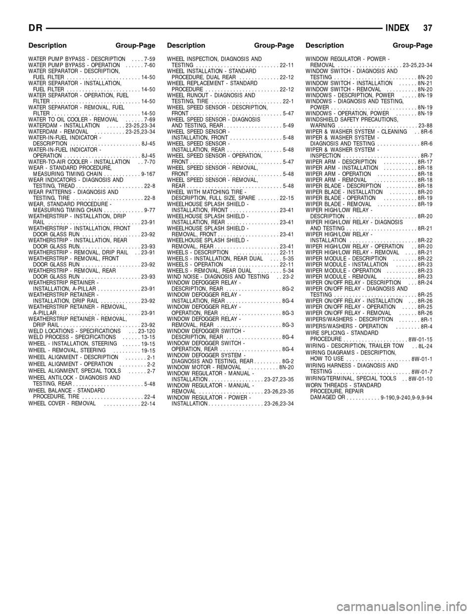
WATER PUMP BYPASS - DESCRIPTION....7-59
WATER PUMP BYPASS - OPERATION......7-60
WATER SEPARATOR - DESCRIPTION,
FUEL FILTER........................14-50
WATER SEPARATOR - INSTALLATION,
FUEL FILTER........................14-50
WATER SEPARATOR - OPERATION, FUEL
FILTER.............................14-50
WATER SEPARATOR - REMOVAL, FUEL
FILTER.............................14-50
WATER TO OIL COOLER - REMOVAL......7-69
WATERDAM - INSTALLATION......23-25,23-34
WATERDAM - REMOVAL..........23-25,23-34
WATER-IN-FUEL INDICATOR -
DESCRIPTION.......................8J-45
WATER-IN-FUEL INDICATOR -
OPERATION.........................8J-45
WATER-TO-AIR COOLER - INSTALLATION . . 7-70
WEAR - STANDARD PROCEDURE,
MEASURING TIMING CHAIN............9-167
WEAR INDICATORS - DIAGNOSIS AND
TESTING, TREAD......................22-8
WEAR PATTERNS - DIAGNOSIS AND
TESTING, TIRE.......................22-8
WEAR, STANDARD PROCEDURE -
MEASURING TIMING CHAIN.............9-77
WEATHERSTRIP - INSTALLATION, DRIP
RAIL..............................23-91
WEATHERSTRIP - INSTALLATION, FRONT
DOOR GLASS RUN...................23-92
WEATHERSTRIP - INSTALLATION, REAR
DOOR GLASS RUN.....................23-93
WEATHERSTRIP - REMOVAL, DRIP RAIL . . 23-91
WEATHERSTRIP - REMOVAL, FRONT
DOOR GLASS RUN...................23-92
WEATHERSTRIP - REMOVAL, REAR
DOOR GLASS RUN...................23-93
WEATHERSTRIP RETAINER -
INSTALLATION, A-PILLAR..............23-91
WEATHERSTRIP RETAINER -
INSTALLATION, DRIP RAIL.............23-92
WEATHERSTRIP RETAINER - REMOVAL,
A-PILLAR...........................23-91
WEATHERSTRIP RETAINER - REMOVAL,
DRIP RAIL..........................23-92
WELD LOCATIONS - SPECIFICATIONS . . . 23-120
WELD PROCESS - SPECIFICATIONS......13-15
WHEEL - INSTALLATION, STEERING
......19-15
WHEEL - REMOVAL, STEERING
.........19-15
WHEEL ALIGNMENT - DESCRIPTION
.......2-1
WHEEL ALIGNMENT - OPERATION
.........2-2
WHEEL ALIGNMENT, SPECIAL TOOLS
......2-7
WHEEL ANTILOCK - DIAGNOSIS AND
TESTING, REAR
.......................5-48
WHEEL BALANCE - STANDARD
PROCEDURE, TIRE
....................22-4
WHEEL COVER - REMOVAL
............22-14WHEEL INSPECTION, DIAGNOSIS AND
TESTING...........................22-11
WHEEL INSTALLATION - STANDARD
PROCEDURE, DUAL REAR.............22-12
WHEEL REPLACEMENT - STANDARD
PROCEDURE........................22-12
WHEEL RUNOUT - DIAGNOSIS AND
TESTING, TIRE.......................22-1
WHEEL SPEED SENSOR - DESCRIPTION,
FRONT..............................5-47
WHEEL SPEED SENSOR - DIAGNOSIS
AND TESTING, REAR...................5-49
WHEEL SPEED SENSOR -
INSTALLATION, FRONT.................5-48
WHEEL SPEED SENSOR -
INSTALLATION, REAR..................5-48
WHEEL SPEED SENSOR - OPERATION,
FRONT..............................5-47
WHEEL SPEED SENSOR - REMOVAL,
FRONT..............................5-48
WHEEL SPEED SENSOR - REMOVAL,
REAR...............................5-48
WHEEL WITH MATCHING TIRE -
DESCRIPTION, FULL SIZE, SPARE.......22-15
WHEELHOUSE SPLASH SHIELD -
INSTALLATION, FRONT................23-41
WHEELHOUSE SPLASH SHIELD -
INSTALLATION, REAR.................23-41
WHEELHOUSE SPLASH SHIELD -
REMOVAL, FRONT....................23-41
WHEELHOUSE SPLASH SHIELD -
REMOVAL, REAR.....................23-41
WHEELS - DESCRIPTION..............22-11
WHEELS - INSTALLATION, REAR DUAL....5-35
WHEELS - OPERATION................22-11
WHEELS - REMOVAL, REAR DUAL........5-34
WIND NOISE - DIAGNOSIS AND TESTING . . 23-2
WINDOW DEFOGGER RELAY -
DESCRIPTION, REAR..................8G-2
WINDOW DEFOGGER RELAY -
INSTALLATION, REAR..................8G-4
WINDOW DEFOGGER RELAY -
OPERATION, REAR....................8G-3
WINDOW DEFOGGER RELAY -
REMOVAL, REAR.....................8G-3
WINDOW DEFOGGER SWITCH -
DESCRIPTION, REAR..................8G-4
WINDOW DEFOGGER SWITCH -
OPERATION, REAR....................8G-4
WINDOW DEFOGGER SYSTEM -
DIAGNOSIS AND TESTING, REAR.........8G-2
WINDOW MOTOR - REMOVAL..........8N-20
WINDOW REGULATOR - MANUAL -
INSTALLATION..................23-27,23-35
WINDOW REGULATOR - MANUAL -
REMOVAL.....................23-26,23-35
WINDOW REGULATOR - POWER -
INSTALLATION..................23-26,23-34WINDOW REGULATOR - POWER -
REMOVAL.....................23-25,23-34
WINDOW SWITCH - DIAGNOSIS AND
TESTING...........................8N-20
WINDOW SWITCH - INSTALLATION......8N-21
WINDOW SWITCH - REMOVAL..........8N-20
WINDOWS - DESCRIPTION, POWER.....8N-19
WINDOWS - DIAGNOSIS AND TESTING,
POWER............................8N-19
WINDOWS - OPERATION, POWER.......8N-19
WINDSHIELD SAFETY PRECAUTIONS,
WARNING..........................23-88
WIPER & WASHER SYSTEM - CLEANING . . 8R-6
WIPER & WASHER SYSTEM -
DIAGNOSIS AND TESTING..............8R-6
WIPER & WASHER SYSTEM -
INSPECTION.........................8R-7
WIPER ARM - DESCRIPTION...........8R-17
WIPER ARM - INSTALLATION...........8R-18
WIPER ARM - OPERATION.............8R-18
WIPER ARM - REMOVAL..............8R-18
WIPER BLADE - DESCRIPTION..........8R-18
WIPER BLADE - INSTALLATION.........8R-20
WIPER BLADE - OPERATION...........8R-19
WIPER BLADE - REMOVAL.............8R-19
WIPER HIGH/LOW RELAY -
DESCRIPTION.......................8R-20
WIPER HIGH/LOW RELAY - DIAGNOSIS
AND TESTING.......................8R-21
WIPER HIGH/LOW RELAY -
INSTALLATION......................8R-22
WIPER HIGH/LOW RELAY - OPERATION . . 8R-20
WIPER HIGH/LOW RELAY - REMOVAL....8R-21
WIPER MODULE - DESCRIPTION........8R-22
WIPER MODULE - INSTALLATION.......8R-23
WIPER MODULE - OPERATION..........8R-23
WIPER MODULE - REMOVAL...........8R-23
WIPER ON/OFF RELAY - DESCRIPTION . . . 8R-24
WIPER ON/OFF RELAY - DIAGNOSIS AND
TESTING...........................8R-25
WIPER ON/OFF RELAY - INSTALLATION . . . 8R-26
WIPER ON/OFF RELAY - OPERATION.....8R-25
WIPER ON/OFF RELAY - REMOVAL......8R-26
WIPERS/WASHERS - DESCRIPTION
.......8R-1
WIPERS/WASHERS - OPERATION
........8R-4
WIRE SPLICING - STANDARD
PROCEDURE
.....................8W-01-15
WIRING - DESCRIPTION, TRAILER TOW
. . 8L-24
WIRING DIAGRAMS - DESCRIPTION,
HOW TO USE
.....................8W-01-1
WIRING HARNESS - DIAGNOSIS AND
TESTING
.........................8W-01-7
WIRING/TERMINAL, SPECIAL TOOLS
. . 8W-01-10
WORN THREADS - STANDARD
PROCEDURE, REPAIR
DAMAGED OR
...........9-190,9-240,9-9,9-94
DRINDEX 37
Description Group-Page Description Group-Page Description Group-Page