1998 DODGE RAM 1500 Engine control 2
[x] Cancel search: Engine control 2Page 1495 of 2627
(6) Remove the wooden dowel rods and rubber
bands from the tappets.
(7) Lubricate the push rods with engine oil and
install in their original location.Verify that they
are seated in the tappets.
(8) Lubricate the valve tips with engine oil and
install the crossheads in their original locations.
(9) Lubricate the crossheads and push rod sockets
with engine oil and install the rocker arms and ped-
estals in their original locations. Tighten bolts to 36
N´m (27 ft. lbs.) torque.
(10)Verify valve lash adjustment (Refer to 9 -
ENGINE/CYLINDER HEAD/INTAKE/EXHAUST
VALVES & SEATS - STANDARD PROCEDURE).
(11) Install the cylinder head cover and reusable
gasket (Refer to 9 - ENGINE/CYLINDER HEAD/
CYLINDER HEAD COVER(S) - INSTALLATION).
(12) Install gear housing cover (Refer to 9 -
ENGINE/VALVE TIMING/GEAR HOUSING COVER
- INSTALLATION). Install front crankshaft dust
seal.
(13) Install the crankshaft damper with the speed
indicator ring (Refer to 9 - ENGINE/ENGINE
BLOCK/VIBRATION DAMPER - INSTALLATION).
(14) Install the fan support/hub assembly Refer to
(Refer to 7 - COOLING/ENGINE/RADIATOR FAN -
INSTALLATION).
(15) Install the power steering pump.
(16) Install accessory drive belt tensioner. Torque
bolt to 43 Nm (32 ft. lbs.).
(17) Install the accessory drive belt (Refer to 7 -
COOLING/ACCESSORY DRIVE/DRIVE BELTS -
INSTALLATION).
(18) Install the charge air cooler (with a/c con-
denser and auxiliary transmission oil cooler, if
equipped) and tighten the mounting bolts to 2 N´m
(17 in. lbs.) torque.
(19) Connect charge air cooler inlet and outlet
pipes. Tighten clamps to 11 N´m (95 in. lbs.) torque.
(20) Install the radiator upper support panel.
(21) Close radiator petcock and lower the radiator
into the engine compartment. Tighten the mounting
bolts to 11 N´m (95 in. lbs.) torque.
(22) Raise vehicle on hoist.
(23) Connect radiator lower hose and install
clamp.
(24) Connect transmission auxiliary oil cooler lines
(if equipped).
(25) Lower vehicle.
(26) Install the fan shroud and tighten the mount-
ing screws to 6 N´m (50 in. lbs.) torque.
(27) Install the electronically controlled viscous
fan/drive assembly. Connect harness connector.(Refer
to 7 - COOLING/ENGINE/RADIATOR FAN -
INSTALLATION).(28) Install the coolant recovery and windshield
washer fluid reservoirs to the fan shroud.
(29) Connect the coolant recovery hose to the radi-
ator filler neck.
(30) Add engine coolant (Refer to 7 - COOLING -
STANDARD PROCEDURE).
(31) Charge A/C system with refrigerant (if A/C
equipped) (Refer to 24 - HEATING & AIR CONDI-
TIONING/PLUMBING - STANDARD PROCEDURE).
(32) Connect the battery negative cables.
(33) Start engine and check for engine oil and cool-
ant leaks.
CONNECTING ROD BEARINGS
STANDARD PROCEDURE - CONNECTING ROD
BEARING AND CRANKSHAFT JOURNAL
CLEARANCE
(1) Measure the connecting rod bore with bearings
removedand the bolts tightened to 100 N´m (73 ft.
lbs.) torque..
(2) Measure the connecting rod bore with the bear-
ingsinstalledand the bolts tightened to 100 N´m
(73 ft. lbs.) torque.
Measure within 20É arc from each side of the part-
ing line. Also measure 90É from parting line.
Record the smallest and largest diameter.
Measure the diameter of the rod journal at the
location shown (Fig. 63). Calculate the average diam-
eter for each side of the journal.
Determine minimum bearing clearance by calculat-
ing the differance between the smallest connecting
rod bore diameter with the bearing installed and the
average diameter for each side of the crankshaft jour-
nal.
Determine the maximum bearing clearance by cal-
culating the difference between the largest connect-
ing rod bore diameter and the average diameter with
the bearing installed for each side of the crankshaft
journal.
DESCRIPTION MEASUREMENT
CONNECTING ROD
BORE, BEARINGS
REMOVEDMIN. 72.99 mm (2.874
in.)
MAX. 73.01 mm (2.875
in.)
CONNECTING ROD
BORE, BEARINGS
INSTALLEDMIN. 69.05 mm (2.719
in.)
MAX. 69.10 mm (2.720
in.)
9 - 272 ENGINE 5.9L DIESELDR
CAMSHAFT & BEARINGS (IN BLOCK) (Continued)
Page 1507 of 2627
(10)For fractured/split type connecting rods,
the long end of the rod must be installed towards the
intake side of the engine.
(a) The connecting rod split/face must face
toward the same side as the piston notch feature
on the skirt. The split face will face toward the
exhaust side of the engine if properly installed.
(11) Install the rod cap and bolts to the connecting
rod. Tighten the connecting rod bolts evenly in 3
steps.
²Tighten the bolts to 30 N´m (22 ft. lbs.) torque.
²Tighten the bolts to 60 N´m (44 ft. lbs.) torque.
²Rotate 60É clockwise.
(12) The crankshaft must rotate freely. Check for
freedom of rotation as the caps are installed. If the
crankshaft does not rotate freely, check the installa-
tion of the rod bearing and the bearing size.
(13) Measure the side clearance between the con-
necting rod and the crankshaft. DO NOT measure
the clearance between the cap and crankshaft.
(14) Install J-jet piston cooling nozzles if equipped.
(15) Install block stiffener. Torque to 43 N´m (32 ft.
lbs.).
(16) Install the suction tube and oil pan (Refer to 9
- ENGINE/LUBRICATION/OIL PAN - INSTALLA-
TION).
(17) Install the cylinder head onto the engine
(Refer to 9 - ENGINE/CYLINDER HEAD - INSTAL-
LATION).
(18) Install a new filter and fill the crankcase with
new engine oil.Prefill the filter with clean oil.
(19) Connect the battery negative cables and start
engine.
PISTON RINGS
STANDARD PROCEDURE - PISTON RING
FITTING
(1) Determine the piston diameter and obtain the
appropriate ring set. The piston rings can be identi-
fied as shown in (Fig. 93).
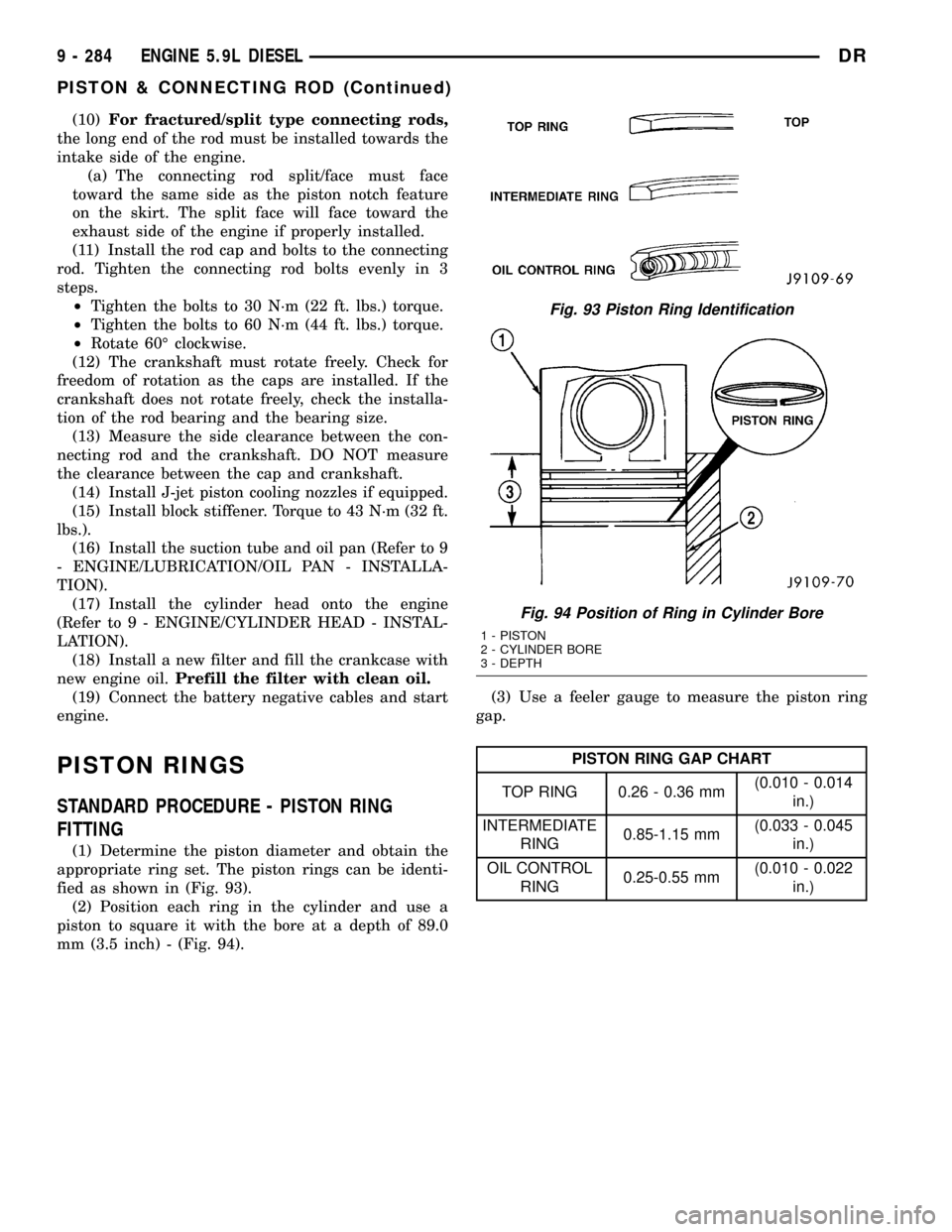
(2) Position each ring in the cylinder and use a
piston to square it with the bore at a depth of 89.0
mm (3.5 inch) - (Fig. 94).(3) Use a feeler gauge to measure the piston ring
gap.
PISTON RING GAP CHART
TOP RING 0.26 - 0.36 mm(0.010 - 0.014
in.)
INTERMEDIATE
RING0.85-1.15 mm(0.033 - 0.045
in.)
OIL CONTROL
RING0.25-0.55 mm(0.010 - 0.022
in.)
Fig. 93 Piston Ring Identification
Fig. 94 Position of Ring in Cylinder Bore
1 - PISTON
2 - CYLINDER BORE
3 - DEPTH
9 - 284 ENGINE 5.9L DIESELDR
PISTON & CONNECTING ROD (Continued)
Page 1508 of 2627
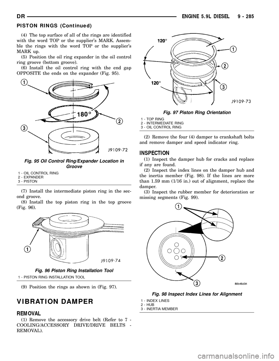
(4) The top surface of all of the rings are identified
with the word TOP or the supplier's MARK. Assem-
ble the rings with the word TOP or the supplier's
MARK up.
(5) Position the oil ring expander in the oil control
ring groove (bottom groove).
(6) Install the oil control ring with the end gap
OPPOSITE the ends on the expander (Fig. 95).
(7) Install the intermediate piston ring in the sec-
ond groove.
(8) Install the top piston ring in the top groove
(Fig. 96).
(9) Position the rings as shown in (Fig. 97).
VIBRATION DAMPER
REMOVAL
(1) Remove the accessory drive belt (Refer to 7 -
COOLING/ACCESSORY DRIVE/DRIVE BELTS -
REMOVAL).(2) Remove the four (4) damper to crankshaft bolts
and remove damper and speed indicator ring.
INSPECTION
(1) Inspect the damper hub for cracks and replace
if any are found.
(2) Inspect the index lines on the damper hub and
the inertia member (Fig. 98). If the lines are more
than 1.59 mm (1/16 in.) out of alignment, replace the
damper.
(3) Inspect the rubber member for deterioration or
missing segments (Fig. 99).Fig. 95 Oil Control Ring/Expander Location in
Groove
1 - OIL CONTROL RING
2 - EXPANDER
3 - PISTON
Fig. 96 Piston Ring Installation Tool
1 - PISTON RING INSTALLATION TOOL
Fig. 97 Piston Ring Orientation
1 - TOP RING
2 - INTERMEDIATE RING
3 - OIL CONTROL RING
Fig. 98 Inspect Index Lines for Alignment
1 - INDEX LINES
2 - HUB
3 - INERTIA MEMBER
DRENGINE 5.9L DIESEL 9 - 285
PISTON RINGS (Continued)
Page 1571 of 2627
OPERATION
Fuel is returned through the fuel pump module
and back into the fuel tank through the fuel filter/
fuel pressure regulator. A separate fuel return line
from the engine to the tank is not used.
The fuel tank assembly consists of: the fuel tank,
fuel pump module assembly, fuel pump module lock-
nut/gasket, and fuel tank check valve (refer to Fuel
Tank Check Valve for information).
A fuel filler/vent tube assembly using a pressure/
vacuum, 1/4 turn fuel filler cap is used. The fuel
filler tube contains a flap door located below the fuel
fill cap.
Also to be considered part of the fuel system is the
evaporation control system. This is designed to
reduce the emission of fuel vapors into the atmo-sphere. The description and function of the Evapora-
tive Control System is found in Emission Control
Systems.
Both fuel filters (at bottom of fuel pump module
and within fuel pressure regulator) are designed for
extended service. They do not require normal sched-
uled maintenance. Filters should only be replaced if
a diagnostic procedure indicates to do so.
STANDARD PROCEDURE - FUEL SYSTEM
PRESSURE RELEASE
Use following procedure if the fuel injector
rail is, or is not equipped with a fuel pressure
test port.
(1) Remove fuel fill cap.
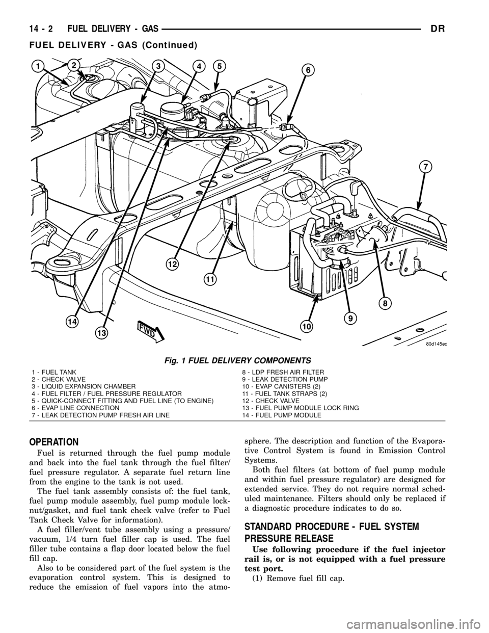
Fig. 1 FUEL DELIVERY COMPONENTS
1 - FUEL TANK 8 - LDP FRESH AIR FILTER
2 - CHECK VALVE 9 - LEAK DETECTION PUMP
3 - LIQUID EXPANSION CHAMBER 10 - EVAP CANISTERS (2)
4 - FUEL FILTER / FUEL PRESSURE REGULATOR 11 - FUEL TANK STRAPS (2)
5 - QUICK-CONNECT FITTING AND FUEL LINE (TO ENGINE) 12 - CHECK VALVE
6 - EVAP LINE CONNECTION 13 - FUEL PUMP MODULE LOCK RING
7 - LEAK DETECTION PUMP FRESH AIR LINE 14 - FUEL PUMP MODULE
14 - 2 FUEL DELIVERY - GASDR
FUEL DELIVERY - GAS (Continued)
Page 1575 of 2627
OPERATION
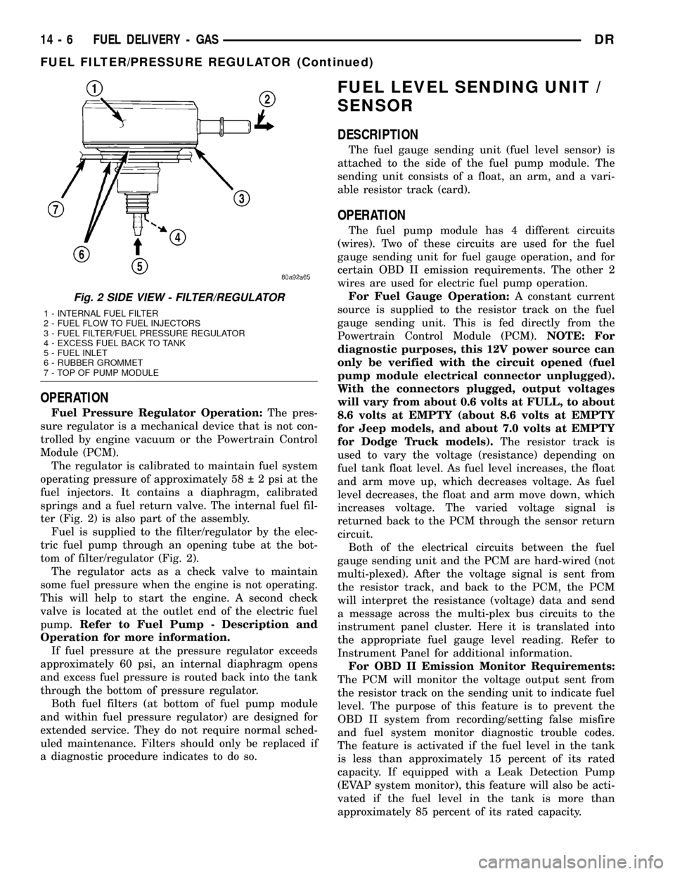
Fuel Pressure Regulator Operation:The pres-
sure regulator is a mechanical device that is not con-
trolled by engine vacuum or the Powertrain Control
Module (PCM).
The regulator is calibrated to maintain fuel system
operating pressure of approximately 58 2 psi at the
fuel injectors. It contains a diaphragm, calibrated
springs and a fuel return valve. The internal fuel fil-
ter (Fig. 2) is also part of the assembly.
Fuel is supplied to the filter/regulator by the elec-
tric fuel pump through an opening tube at the bot-
tom of filter/regulator (Fig. 2).
The regulator acts as a check valve to maintain
some fuel pressure when the engine is not operating.
This will help to start the engine. A second check
valve is located at the outlet end of the electric fuel
pump.Refer to Fuel Pump - Description and
Operation for more information.
If fuel pressure at the pressure regulator exceeds
approximately 60 psi, an internal diaphragm opens
and excess fuel pressure is routed back into the tank
through the bottom of pressure regulator.
Both fuel filters (at bottom of fuel pump module
and within fuel pressure regulator) are designed for
extended service. They do not require normal sched-
uled maintenance. Filters should only be replaced if
a diagnostic procedure indicates to do so.
FUEL LEVEL SENDING UNIT /
SENSOR
DESCRIPTION
The fuel gauge sending unit (fuel level sensor) is
attached to the side of the fuel pump module. The
sending unit consists of a float, an arm, and a vari-
able resistor track (card).
OPERATION
The fuel pump module has 4 different circuits
(wires). Two of these circuits are used for the fuel
gauge sending unit for fuel gauge operation, and for
certain OBD II emission requirements. The other 2
wires are used for electric fuel pump operation.
For Fuel Gauge Operation:A constant current
source is supplied to the resistor track on the fuel
gauge sending unit. This is fed directly from the
Powertrain Control Module (PCM).NOTE: For
diagnostic purposes, this 12V power source can
only be verified with the circuit opened (fuel
pump module electrical connector unplugged).
With the connectors plugged, output voltages
will vary from about 0.6 volts at FULL, to about
8.6 volts at EMPTY (about 8.6 volts at EMPTY
for Jeep models, and about 7.0 volts at EMPTY
for Dodge Truck models).The resistor track is
used to vary the voltage (resistance) depending on
fuel tank float level. As fuel level increases, the float
and arm move up, which decreases voltage. As fuel
level decreases, the float and arm move down, which
increases voltage. The varied voltage signal is
returned back to the PCM through the sensor return
circuit.
Both of the electrical circuits between the fuel
gauge sending unit and the PCM are hard-wired (not
multi-plexed). After the voltage signal is sent from
the resistor track, and back to the PCM, the PCM
will interpret the resistance (voltage) data and send
a message across the multi-plex bus circuits to the
instrument panel cluster. Here it is translated into
the appropriate fuel gauge level reading. Refer to
Instrument Panel for additional information.
For OBD II Emission Monitor Requirements:
The PCM will monitor the voltage output sent from
the resistor track on the sending unit to indicate fuel
level. The purpose of this feature is to prevent the
OBD II system from recording/setting false misfire
and fuel system monitor diagnostic trouble codes.
The feature is activated if the fuel level in the tank
is less than approximately 15 percent of its rated
capacity. If equipped with a Leak Detection Pump
(EVAP system monitor), this feature will also be acti-
vated if the fuel level in the tank is more than
approximately 85 percent of its rated capacity.
Fig. 2 SIDE VIEW - FILTER/REGULATOR
1 - INTERNAL FUEL FILTER
2 - FUEL FLOW TO FUEL INJECTORS
3 - FUEL FILTER/FUEL PRESSURE REGULATOR
4 - EXCESS FUEL BACK TO TANK
5 - FUEL INLET
6 - RUBBER GROMMET
7 - TOP OF PUMP MODULE
14 - 6 FUEL DELIVERY - GASDR
FUEL FILTER/PRESSURE REGULATOR (Continued)
Page 1586 of 2627
(15) Install air duct to air box.
(16) Connect battery cable to battery.
(17) Start engine and check for leaks.
5.7L V-8
(1) If fuel injectors are to be installed, refer to Fuel
Injector Removal/Installation.
(2) Clean out fuel injector machined bores in
intake manifold.
(3) Apply a small amount of engine oil to each fuel
injector o-ring. This will help in fuel rail installation.
(4) Position fuel rail/fuel injector assembly to
machined injector openings in intake manifold.
(5) Guide each injector into intake manifold. Be
careful not to tear injector o-rings.
(6) Pushrightside of fuel rail down until fuel
injectors have bottomed on shoulders. Pushleftfuel
rail down until injectors have bottomed on shoulders.
(7) Install 4 fuel rail holdown clamps and 4 mount-
ing bolts. Refer to Torque Specifications.
(8) Position spark plug cable tray and cable assem-
bly to intake manifold. Snap 4 cable tray retaining
clips into intake manifold.
(9) Install all cables to spark plugs and ignition
coils.
(10) Connect electrical connector to throttle body.
(11) Install electrical connectors to all 8 ignition
coils. Refer to Ignition Coil Removal/Installation.
(12) Connect electrical connector to throttle body.
(13) Connect electrical connectors at all fuel injec-
tors. To install connector, refer to (Fig. 17). Push con-
nector onto injector (1) and then push and lock red
colored slider (2). Verify connector is locked to injec-
tor by lightly tugging on connector.
(14) Connect fuel line latch clip and fuel line to
fuel rail. Refer to Quick-Connect Fittings.
(15) Install air resonator to throttle body (2 bolts).
(16) Install flexible air duct to air box.
(17) Connect battery cable to battery.
(18) Start engine and check for leaks.
FUEL TANK
DESCRIPTION
The fuel tank is constructed of a plastic material.
Its main functions are for fuel storage and for place-
ment of the fuel pump module, and (if equipped) cer-
tain ORVR components.
OPERATION
All models pass a full 360 degree rollover test
without fuel leakage. To accomplish this, fuel and
vapor flow controls are required for all fuel tank con-
nections.Two check (control) valves are mounted into the
top of the fuel tank. Refer to Fuel Tank Check Valve
for additional information.
An evaporation control system is connected to the
fuel tank to reduce emissions of fuel vapors into the
atmosphere. When fuel evaporates from the fuel
tank, vapors pass through vent hoses or tubes to a
charcoal canister where they are temporarily held.
When the engine is running, the vapors are drawn
into the intake manifold. Certain models are also
equipped with a self-diagnosing system using a Leak
Detection Pump (LDP) and/or an On-Board Refueling
Vapor Recovery (ORVR) system. Refer to Emission
Control System for additional information.
REMOVAL- EXCEPT DIESEL
Fuel Tank Draining
WARNING: THE FUEL SYSTEM MAY BE UNDER
CONSTANT FUEL PRESSURE EVEN WITH THE
ENGINE OFF. THIS PRESSURE MUST BE
RELEASED BEFORE SERVICING FUEL TANK.
Two different procedures may be used to drain fuel
tank: through the fuel fill fitting on tank, or using
the DRBtscan tool. Due to a one-way check valve
installed into the fuel fill opening fitting at the tank,
the tank cannot be drained conventionally at the fill
cap.
The quickest draining procedure involves removing
the rubber fuel fill hose.
As an alternative procedure, the electric fuel pump
may be activated allowing tank to be drained at fuel
rail connection. Refer to DRB scan tool for fuel pump
activation procedures. Before disconnecting fuel line
at fuel rail, release fuel pressure. Refer to the Fuel
System Pressure Release Procedure for procedures.
Attach end of special test hose tool number 6541,
6539, 6631 or 6923 at fuel rail disconnection (tool
number will depend on model and/or engine applica-
tion). Position opposite end of this hose tool to an
approved gasoline draining station. Activate fuel
pump and drain tank until empty.
If electric fuel pump is not operating, fuel must be
drained through fuel fill fitting at tank. Refer to fol-
lowing procedures.
(1) Release fuel system pressure.
(2) Raise vehicle.
(3) Thoroughly clean area around fuel fill fitting
and rubber fuel fill hose at tank.
(4) If vehicle is equipped with 4 doors and a 6 foot
(short) box, remove left-rear tire/wheel.
(5) Loosen clamp (Fig. 23) and disconnect rubber
fuel fill hose at tank fitting. Using an approved gas
holding tank, drain fuel tank through this fitting.
DRFUEL DELIVERY - GAS 14 - 17
FUEL RAIL (Continued)
Page 1590 of 2627
FUEL INJECTION - GAS
TABLE OF CONTENTS
page page
ACCELERATOR PEDAL
REMOVAL.............................21
INSTALLATION.........................21
ACCELERATOR PEDAL POSITION SENSOR
DESCRIPTION.........................22
OPERATION...........................22
REMOVAL.............................22
INSTALLATION.........................22
CRANKSHAFT POSITION SENSOR
DESCRIPTION.........................23
OPERATION...........................23
REMOVAL.............................24
INSTALLATION.........................25
FUEL INJECTOR
DESCRIPTION.........................26
OPERATION
OPERATION - FUEL INJECTOR..........26
OPERATION - PCM OUTPUT............27
REMOVAL.............................27
INSTALLATION.........................27
FUEL PUMP RELAY
DESCRIPTION.........................27
OPERATION...........................27
REMOVAL.............................28
INSTALLATION.........................28
IDLE AIR CONTROL MOTOR
DESCRIPTION.........................28
OPERATION...........................28
REMOVAL.............................29
INSTALLATION.........................29INTAKE AIR TEMPERATURE SENSOR
DESCRIPTION.........................30
OPERATION...........................30
REMOVAL.............................30
INSTALLATION.........................31
MAP SENSOR
DESCRIPTION.........................32
OPERATION...........................32
REMOVAL.............................33
INSTALLATION.........................34
OXYGEN SENSOR
DESCRIPTION.........................35
REMOVAL.............................35
INSTALLATION.........................36
PTO SWITCH
DESCRIPTION.........................36
OPERATION...........................36
THROTTLE BODY
DESCRIPTION.........................36
OPERATION...........................36
REMOVAL.............................36
INSTALLATION.........................37
THROTTLE CONTROL CABLE
REMOVAL.............................38
INSTALLATION.........................40
THROTTLE POSITION SENSOR
DESCRIPTION.........................41
OPERATION...........................41
REMOVAL.............................41
INSTALLATION.........................43
ACCELERATOR PEDAL
REMOVAL
The following procedure applies only to vehicles
without the Adjustable Pedal Package (code XAP).
The accelerator pedal is serviced as a complete
assembly including the bracket.
The accelerator cable is connected to the upper
part of the accelerator pedal arm by a plastic
retainer (clip) (Fig. 1). This plastic retainer snaps
into the top of the accelerator pedal arm.
(1) From inside the vehicle, hold up accelerator
pedal. Remove plastic cable retainer (clip) and throt-
tle cable core wire from upper end of accelerator
pedal arm (Fig. 1). Plastic cable retainer (clip) snaps
into pedal arm.(2) Remove 2 accelerator pedal mounting bracket
nuts. Remove accelerator pedal assembly.INSTALLATION
(1) Place accelerator pedal assembly over 2 studs.
(2) Install and tighten 2 mounting nuts. Refer to
Torque Specifications.
(3) Slide throttle cable into opening slot in top of
pedal arm.
(4) Push plastic cable retainer (clip) into accelera-
tor pedal arm opening until it snaps into place.
(5) Before starting engine, operate accelerator
pedal to check for any binding.
DRFUEL INJECTION - GAS 14 - 21
Page 1592 of 2627
(5) Position APPS assembly to bottom of battery
tray and install 3 bolts. Refer to Torque Specifica-
tions.
(6) Install wheelhouse liner. Refer to Body.
(7)The 5.7L V-8 engine is equipped with a
fully electronic accelerator pedal position sen-
sor. If equipped with a 5.7L, also perform the
following 3 steps:
(a) Connect negative battery cable to battery.
(b) Turn ignition switch ON, but do not crank
engine.
(c) Leave ignition switch ON for a minimum of
10 seconds. This will allow PCM to learn electrical
parameters.
(d) The DRB IIItScan Tool may also be used to
learn electrical parameters. Go to the Miscella-
neous menu, and then select ETC Learn.
(8) If the previous step is not performed, a Diag-
nostic Trouble Code (DTC) will be set.
(9) If necessary, use DRB IIItScan Tool to erase
any Diagnostic Trouble Codes (DTC's) from PCM.
CRANKSHAFT POSITION
SENSOR
DESCRIPTION
3.7L V-6
The Crankshaft Position (CKP) sensor is mounted
into the right rear side of the cylinder block. It is
positioned and bolted into a machined hole.
4.7L V-8
The Crankshaft Position (CKP) sensor is mounted
into the right rear side of the cylinder block. It is
positioned and bolted into a machined hole.
5.7L V-8
The Crankshaft Position (CKP) sensor is mounted
into the right rear side of the cylinder block. It is
positioned and bolted into a machined hole.
OPERATION
3.7L V-6
Engine speed and crankshaft position are provided
through the CKP (Crankshaft Position) sensor. The
sensor generates pulses that are the input sent to the
Powertrain Control Module (PCM). The PCM inter-
prets the sensor input to determine the crankshaft
position. The PCM then uses this position, along with
other inputs, to determine injector sequence and igni-
tion timing.
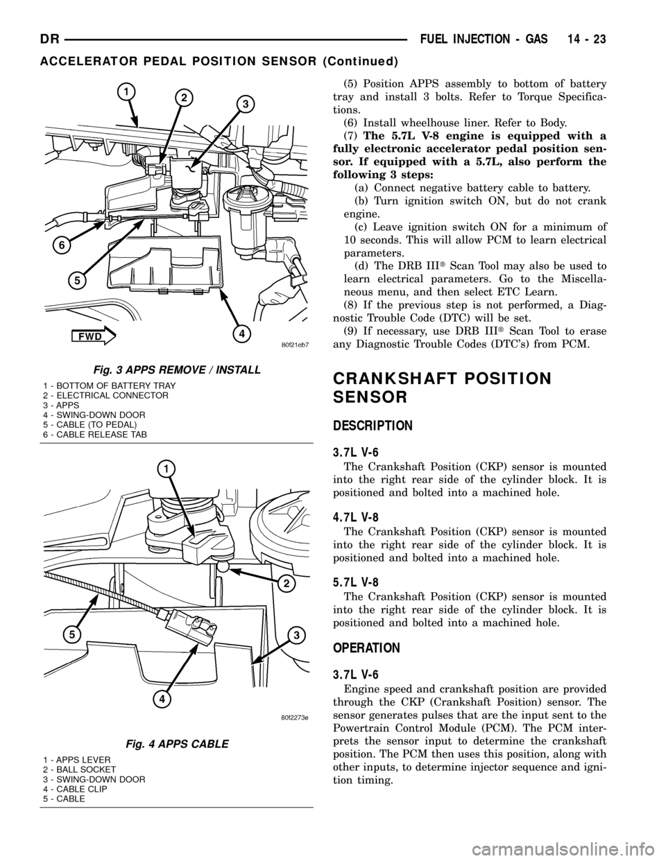
Fig. 3 APPS REMOVE / INSTALL
1 - BOTTOM OF BATTERY TRAY
2 - ELECTRICAL CONNECTOR
3 - APPS
4 - SWING-DOWN DOOR
5 - CABLE (TO PEDAL)
6 - CABLE RELEASE TAB
Fig. 4 APPS CABLE
1 - APPS LEVER
2 - BALL SOCKET
3 - SWING-DOWN DOOR
4 - CABLE CLIP
5 - CABLE
DRFUEL INJECTION - GAS 14 - 23
ACCELERATOR PEDAL POSITION SENSOR (Continued)