1998 DODGE RAM 1500 Speed sensor
[x] Cancel search: Speed sensorPage 26 of 2627

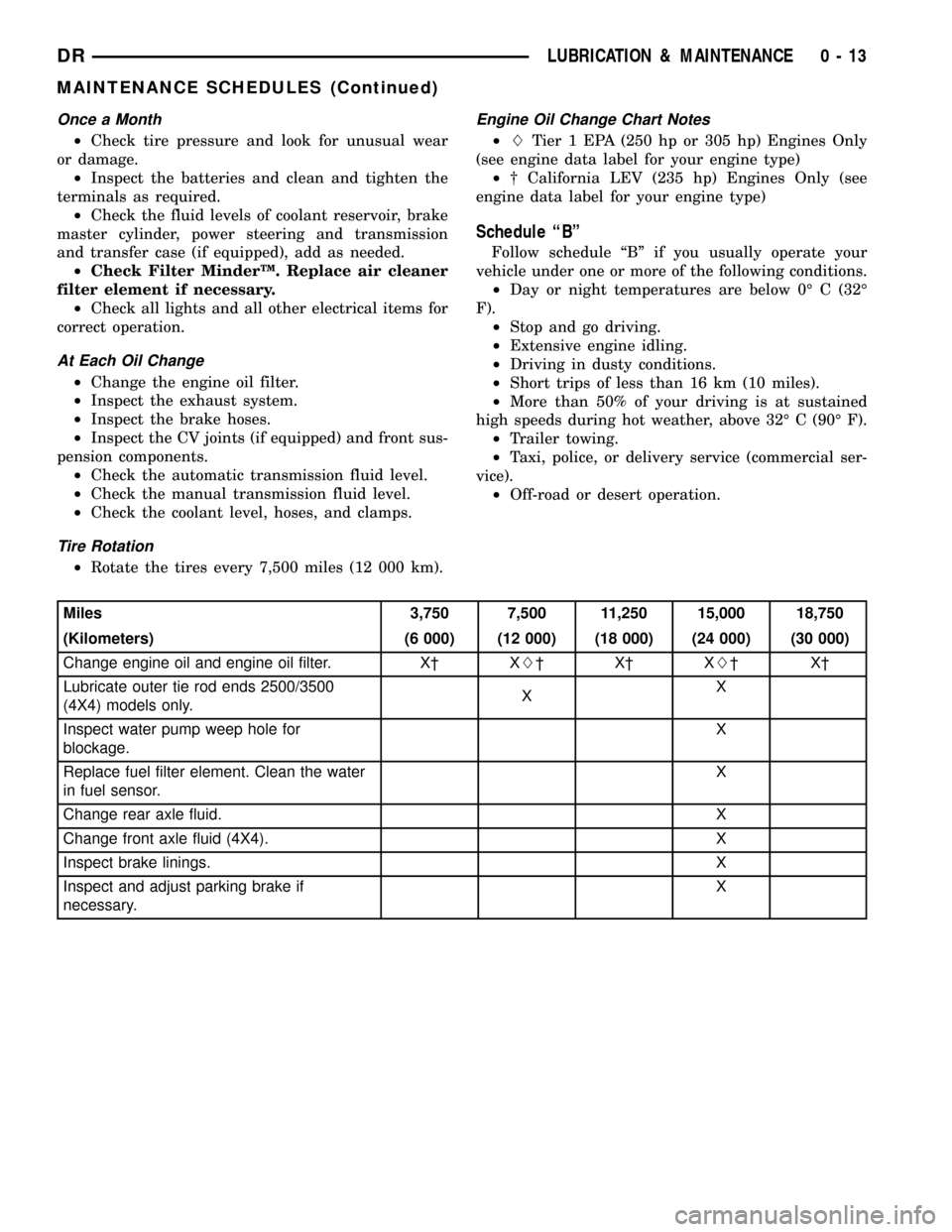
Once a Month
²Check tire pressure and look for unusual wear
or damage.
²Inspect the batteries and clean and tighten the
terminals as required.
²Check the fluid levels of coolant reservoir, brake
master cylinder, power steering and transmission
and transfer case (if equipped), add as needed.
²Check Filter MinderŸ. Replace air cleaner
filter element if necessary.
²Check all lights and all other electrical items for
correct operation.
At Each Oil Change
²Change the engine oil filter.
²Inspect the exhaust system.
²Inspect the brake hoses.
²Inspect the CV joints (if equipped) and front sus-
pension components.
²Check the automatic transmission fluid level.
²Check the manual transmission fluid level.
²Check the coolant level, hoses, and clamps.
Tire Rotation
²Rotate the tires every 7,500 miles (12 000 km).
Engine Oil Change Chart Notes
²LTier 1 EPA (250 hp or 305 hp) Engines Only
(see engine data label for your engine type)
²² California LEV (235 hp) Engines Only (see
engine data label for your engine type)
Schedule ªBº
Follow schedule ªBº if you usually operate your
vehicle under one or more of the following conditions.
²Day or night temperatures are below 0É C (32É
F).
²Stop and go driving.
²Extensive engine idling.
²Driving in dusty conditions.
²Short trips of less than 16 km (10 miles).
²More than 50% of your driving is at sustained
high speeds during hot weather, above 32É C (90É F).
²Trailer towing.
²Taxi, police, or delivery service (commercial ser-
vice).
²Off-road or desert operation.
Miles 3,750 7,500 11,250 15,000 18,750
(Kilometers) (6 000) (12 000) (18 000) (24 000) (30 000)
Change engine oil and engine oil filter. X² XL²X²XL²X²
Lubricate outer tie rod ends 2500/3500
(4X4) models only.XX
Inspect water pump weep hole for
blockage.X
Replace fuel filter element. Clean the water
in fuel sensor.X
Change rear axle fluid. X
Change front axle fluid (4X4). X
Inspect brake linings.X
Inspect and adjust parking brake if
necessary.X
DRLUBRICATION & MAINTENANCE 0 - 13
MAINTENANCE SCHEDULES (Continued)
Page 51 of 2627

LARGE BUSHING
NOTE: Extreme pressure lubrication must be used
on the threaded portions of the tool. This will
increase the longevity of the tool and insure proper
operation during the removal and installation pro-
cess.
(1) Install the new bushing into the lower control
arm using special tools 8836-2 (receiver), 8836-1
(driver), 8836-4 (spacer) with the bearing and the
threaded rod (8839) (Fig. 12).
SMALL BUSHING
(1) Install the small bushings into the lower con-
trol arm using tools 8836-7 (driver), 8836-2 (receiver),
8836±3 (spacer) and the bearing with the threaded
rod (8839) (Fig. 13).
(1) Remove the control arm from the vise.
(2) Install the lower control arm (Refer to 2 - SUS-
PENSION/FRONT/LOWER CONTROL ARM -
INSTALLATION).
(3) Reset the vehicle ride height (Refer to 2 - SUS-
PENSION/WHEEL ALIGNMENT - STANDARD
PROCEDURE).
(4) Perform a wheel alignment (Refer to 2 - SUS-
PENSION/WHEEL ALIGNMENT - STANDARD
PROCEDURE).
HUB / BEARING
REMOVAL
REMOVAL - 4X4
(1) Raise and support the vehicle.
(2) Remove the wheel and tire assembly.
(3) Remove the brake caliper and rotor (Refer to 5
- BRAKES/HYDRAULIC/MECHANICAL/ROTORS -
REMOVAL).
(4) Remove the ABS wheel speed sensor if
equipped, (Refer to 5 - BRAKES/ELECTRICAL/
FRONT WHEEL SPEED SENSOR - REMOVAL).
(5) Remove the halfshaft nut.
Fig. 11 TORSION BAR CROSS MEMBER BUSHING -
INSTALLATION
1 - 8835-2
2 - 8835-4
3 - 8835-3
4 - 8838
Fig. 12 LARGE LOWER CONTROL ARM BUSHING -
INSTALL
1 - 8836-1 (DRIVER)
2 - 8839 (THREADED ROD)
3 - 8836-2 (RECEIVER)
4 - 8836-4 (SPACER)
Fig. 13 SMALL LOWER CONTROL ARM BUSHING -
INSTALL
1 - 8836-2 (RECEIVER)
2 - 8839 (THREADED ROD)
3 - 8836-3 (SPACER)
4 - 8836-7 (DRIVER)
2 - 16 FRONT - INDEPENDENT FRONT SUSPENSIONDR
BUSHINGS (Continued)
Page 52 of 2627

NOTE: Do not strike the knuckle with a hammer to
remove the tie rod end or the ball joint. Damage to
the steering knuckle will occur.
(6) Remove the tie rod end nut and separate the
tie rod from the knuckle using special tool 8677.
(7) Remove the upper ball joint nut and separate
the upper ball joint from the knuckle using special
tool 8677.
(8) Pull down on the steering knuckle to separate
the halfshaft from the hub/bearing.
(9) Remove the three hub/bearing mounting bolts
from the steering knuckle (Fig. 14).
(10) Slide the hub/bearing out of the steering
knuckle (Fig. 14).
(11) Remove the brake dust shield.
REMOVAL - 4X2
(1) Raise and support the vehicle.
(2) Remove the wheel and tire assembly.
(3) Remove the brake caliper and rotor (Refer to 5
- BRAKES/HYDRAULIC/MECHANICAL/ROTORS -
REMOVAL).
(4) Remove the ABS wheel speed sensor if
equipped, (Refer to 5 - BRAKES/ELECTRICAL/
FRONT WHEEL SPEED SENSOR - REMOVAL)
(Fig. 15)
(5) Remove the three hub/bearing mounting bolts
from the steering knuckle (Fig. 15).
(6) Slide the hub/bearing out of the steering
knuckle (Fig. 15).
(7) Remove the brake dust shield (Fig. 15).
INSTALLATION
INSTALLATION - 4X4
(1) Install the brake dust shield (Fig. 16).
(2) Install the hub/bearing into the steering
knuckle and tighten the bolts to 163 N´m (120 ft.
lbs.) (Fig. 16).
(3) Install the brake rotor and caliper (Refer to 5 -
BRAKES/HYDRAULIC/MECHANICAL/ROTORS -
INSTALLATION).
Fig. 14 HALFSHAFT / HUB/BEARING
1 - HUB/BEARING MOUNTING NUTS
2 - HALF SHAFT
Fig. 15 HUB/BEARING 4X2
1 - HUB/BEARING
2 - DUST SHIELD
3 - STEERING KNUCKLE
4 - WHEEL SPEED SENSOR WIRE
5 - HUB/BEARING MOUNTING NUT
Fig. 16 HUB/BEARING 4X4
1 - HUB/BEARING
2 - DUST SHIELD
3 - STEERING KNUCKLE
4- WHEEL SPEED SENSOR WIRE
5 - HUB/BEARING MOUNTING NUT
DRFRONT - INDEPENDENT FRONT SUSPENSION 2 - 17
HUB / BEARING (Continued)
Page 53 of 2627

(4) Install the ABS wheel speed sensor if equipped
(Refer to 5 - BRAKES/ELECTRICAL/FRONT
WHEEL SPEED SENSOR - INSTALLATION).
(5) Install the upper ball joint nut to the steering
knuckle and tighten to 54 N´m (40 ft. lbs.) (on 1500
series only an additional 90É turn).
(6) Install the tie rod end nut to the steering
knuckle and tighten to 61 N´m (45 ft. lbs.) then an
additional 90É.
(7) Install the halfshaft nut and tighten to 251
N´m (185 ft. lbs.).
(8) Install the wheel and tire assembly (Refer to 22
- TIRES/WHEELS/WHEELS - STANDARD PROCE-
DURE).
(9) Remove the support and lower vehicle.
INSTALLATION - 4X2
(1) Install the brake dust shield (Fig. 15).
(2) Install the hub/bearing into the steering
knuckle and tighten the bolts to 163 N´m (120 ft.
lbs.) (Fig. 15).
(3) Install the brake rotor and caliper (Refer to 5 -
BRAKES/HYDRAULIC/MECHANICAL/ROTORS -
INSTALLATION).
(4) Install the ABS wheel speed sensor if equipped
(Refer to 5 - BRAKES/ELECTRICAL/FRONT
WHEEL SPEED SENSOR - INSTALLATION) (Fig.
15).
(5) Install the wheel and tire assembly (Refer to 22
- TIRES/WHEELS/WHEELS - STANDARD PROCE-
DURE).
(6) Remove the support and lower vehicle.
KNUCKLE
DESCRIPTION
The knuckle is a single casting with legs machined
for the upper and lower ball joints. The knuckle also
has machined mounting locations for the front brake
calipers and hub bearing.
OPERATION
The steering knuckle pivot between the upper and
lower ball joint. Steering linkage attached to the
knuckle allows the vehicle to be steered.
REMOVAL
(1) Raise and support the vehicle.
(2) Remove the wheel and tire assembly.
(3) Remove the brake caliper, rotor (Refer to 5 -
BRAKES/HYDRAULIC/MECHANICAL/ROTORS -
REMOVAL), shield and ABS wheel speed sensor if
equipped (Refer to 5 - BRAKES/ELECTRICAL/
FRONT WHEEL SPEED SENSOR - REMOVAL).
(4) Remove the front halfshaft nut (if equipped).(5) Remove the tie rod end nut. Separate the tie
rod from the knuckle with Remover 8677.
CAUTION: When installing Remover 8677 to sepa-
rate the ball joint, be careful not to damage the ball
joint seal.
(6) Remove the upper ball joint nut. Separate the
ball joint from the knuckle with Remover 8677 (Fig.
17)
(7) Remove the lower ball joint nut. Separate the
ball joint from the knuckle with Remover 8677 (Fig.
18) and remove the knuckle.
Fig. 17 STEERING KNUCKLE
1 - STEERING KNUCKLE
2 - SHOCK
3 - HALFSHAFT
4 - DISC BRAKE CALIPER
5 - HUB/BEARING
Fig. 18 LOWER BALL JOINT SEPARATION
1 - STEERING KNUCKLE
2 - SPECIAL TOOL 8677
2 - 18 FRONT - INDEPENDENT FRONT SUSPENSIONDR
HUB / BEARING (Continued)
Page 54 of 2627

(8) Remove the hub/bearing from the steering
knuckle (Refer to 2 - SUSPENSION/FRONT/HUB /
BEARING - REMOVAL).
INSTALLATION
CAUTION: The ball joint stud tapers must be
CLEAN and DRY before installing the knuckle.
Clean the stud tapers with mineral spirits to remove
dirt and grease.
NOTE: When installing hub/bearing with ABS
brakes, position the speed sensor opening towards
the front of the vehicle.
(1) Install the hub/bearing to the steering knuckle
and tighten the bolts to 163 N´m (120 ft. lbs.)(LD) or
176 N´m (130 ft. lbs.)(HD 4X2) (Fig. 19).
(2) Install the knuckle onto the upper and lower
ball joints (Fig. 19).
(3) Install the upper and lower ball joint nuts.
Tighten the upper ball joint nut to 54 N´m (40 ft.
lbs.) (on 1500 series only an additional 90É turn is
required) and the lower ball joint nut to 52 N´m (38
ft. lbs.)(on 1500 series only an additional 90É turn is
required)(LD) or 135 N´m (100 ft. lbs.)(HD 4X2).
(4) Remove the hydraulic jack from the lower sus-
pension arm.
(5) Install the tie rod end and tighten the nut to
61 N´m (45 ft. lbs.).
(6) Install the front halfshaft into the hub/bearing
(if equipped).
(7) Install the the halfshaft nut and tighten to 251
N´m (185 ft. lbs.) (if equipped).(8) Install the ABS wheel speed sensor if equipped
(Refer to 5 - BRAKES/ELECTRICAL/FRONT
WHEEL SPEED SENSOR - INSTALLATION) and
brake shield, rotor and caliper (Refer to 5 - BRAKES/
HYDRAULIC/MECHANICAL/ROTORS - INSTALLA-
TION).
(9) Install the wheel and tire assembly (Refer to 22
- TIRES/WHEELS/WHEELS - STANDARD PROCE-
DURE).
(10) Remove the support and lower the vehicle.
(11) Perform a wheel alignment (Refer to 2 - SUS-
PENSION/WHEEL ALIGNMENT - STANDARD
PROCEDURE).
LOWER BALL JOINT
DIAGNOSIS AND TESTING - LOWER BALL
JOINT
NOTE: If the ball joint is equipped with a lubrication
fitting, grease the joint then road test the vehicle
before performing test.
(1) Raise the front of the vehicle. Place safety floor
stands under both lower control arms as far outboard
as possible. Lower the vehicle to allow the stands to
support some or all of the vehicle weight.
(2) Mount a dial indicator solidly to the topside of
the lower control arm and then zero the dial indica-
tor.
(3) Position the indicator plunger against the bot-
tom surface of the steering knuckle.
NOTE: The dial indicator plunger must be perpen-
dicular to the machined surface of the steering
knuckle.
(4) Position a pry bar under the tire assembly. Pry
upwards on the tire assembly.
(5) If the travel exceeds 0.5 mm (0.020 in.), replace
the lower ball joint (Refer to 2 - SUSPENSION/
FRONT/LOWER BALL JOINT - REMOVAL).
REMOVAL
(1) Remove the tire and wheel assembly.
(2) Remove the brake caliper and rotor (Refer to 5
- BRAKES/HYDRAULIC/MECHANICAL/ROTORS -
REMOVAL).
(3) Disconnect the tie rod from the steering
knuckle (Refer to 19 - STEERING/LINKAGE/TIE
ROD END - REMOVAL).
(4) Remove the steering knuckle (Fig. 20)(Refer to
2 - SUSPENSION/FRONT/KNUCKLE - REMOVAL).
(5) Move the halfshaft to the side and support the
halfshaft out of the way (If Equipped).
Fig. 19 STEERING KNUCKLE
1 - STEERING KNUCKLE
2 - LOWER CONTROL ARM
3 - LOWER BALL JOINT NUT
DRFRONT - INDEPENDENT FRONT SUSPENSION 2 - 19
KNUCKLE (Continued)
Page 66 of 2627

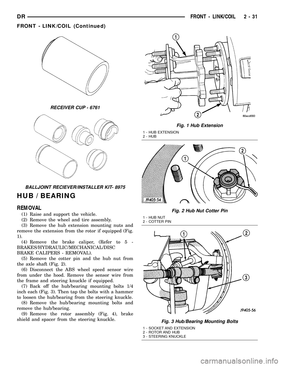
HUB / BEARING
REMOVAL
(1) Raise and support the vehicle.
(2) Remove the wheel and tire assembly.
(3) Remove the hub extension mounting nuts and
remove the extension from the rotor if equipped (Fig.
1).
(4) Remove the brake caliper, (Refer to 5 -
BRAKES/HYDRAULIC/MECHANICAL/DISC
BRAKE CALIPERS - REMOVAL).
(5) Remove the cotter pin and the hub nut from
the axle shaft (Fig. 2).
(6) Disconnect the ABS wheel speed sensor wire
from under the hood. Remove the sensor wire from
the frame and steering knuckle if equipped.
(7) Back off the hub/bearing mounting bolts 1/4
inch each (Fig. 3). Then tap the bolts with a hammer
to loosen the hub/bearing from the steering knuckle.
(8) Remove the hub/bearing mounting bolts and
remove the hub/bearing.
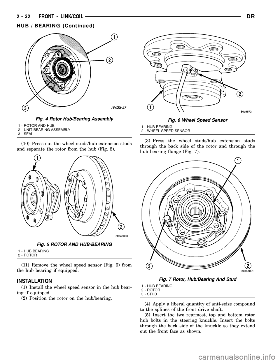
(9) Remove the rotor assembly (Fig. 4), brake
shield and spacer from the steering knuckle.
RECEIVER CUP - 6761
BALLJOINT RECIEVER/INSTALLER KIT- 8975
Fig. 1 Hub Extension
1 - HUB EXTENSION
2 - HUB
Fig. 2 Hub Nut Cotter Pin
1 - HUB NUT
2 - COTTER PIN
Fig. 3 Hub/Bearing Mounting Bolts
1 - SOCKET AND EXTENSION
2 - ROTOR AND HUB
3 - STEERING KNUCKLE
DRFRONT - LINK/COIL 2 - 31
FRONT - LINK/COIL (Continued)
Page 67 of 2627

(10) Press out the wheel studs/hub extension studs
and separate the rotor from the hub (Fig. 5).
(11) Remove the wheel speed sensor (Fig. 6) from
the hub bearing if equipped.
INSTALLATION
(1) Install the wheel speed sensor in the hub bear-
ing if equipped.
(2) Position the rotor on the hub/bearing.(3) Press the wheel studs/hub extension studs
through the back side of the rotor and through the
hub bearing flange (Fig. 7).
(4) Apply a liberal quantity of anti-seize compound
to the splines of the front drive shaft.
(5) Insert the two rearmost, top and bottom rotor
hub bolts in the steering knuckle. Insert the bolts
through the back side of the knuckle so they extend
out the front face as shown.
Fig. 4 Rotor Hub/Bearing Assembly
1 - ROTOR AND HUB
2 - UNIT BEARING ASSEMBLY
3 - SEAL
Fig. 5 ROTOR AND HUB/BEARING
1 - HUB BEARING
2 - ROTOR
Fig. 6 Wheel Speed Sensor
1 - HUB BEARING
2 - WHEEL SPEED SENSOR
Fig. 7 Rotor, Hub/Bearing And Stud
1 - HUB BEARING
2 - ROTOR
3 - STUD
2 - 32 FRONT - LINK/COILDR
HUB / BEARING (Continued)
Page 68 of 2627

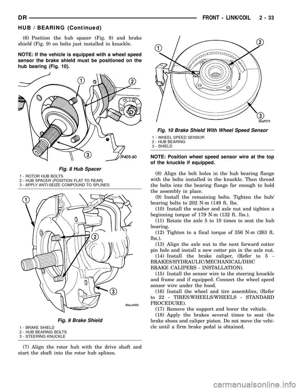
(6) Position the hub spacer (Fig. 8) and brake
shield (Fig. 9) on bolts just installed in knuckle.
NOTE: If the vehicle is equipped with a wheel speed
sensor the brake shield must be positioned on the
hub bearing (Fig. 10).
(7) Align the rotor hub with the drive shaft and
start the shaft into the rotor hub splines.NOTE: Position wheel speed sensor wire at the top
of the knuckle if equipped.
(8) Align the bolt holes in the hub bearing flange
with the bolts installed in the knuckle. Then thread
the bolts into the bearing flange far enough to hold
the assembly in place.
(9) Install the remaining bolts. Tighten the hub/
bearing bolts to 202 N´m (149 ft. lbs.
(10) Install the washer and axle nut and tighten a
beginning torque of 179 N´m (132 ft. lbs.).
(11) Rotate the axle 5 to 10 times to seat the hub
bearing.
(12) Tighten to a final torque of 356 N´m (263 ft.
lbs.).
(13) Align the axle nut to the next forward cotter
pin hole and install a new cotter pin in the axle nut.
(14) Install the brake caliper, (Refer to 5 -
BRAKES/HYDRAULIC/MECHANICAL/DISC
BRAKE CALIPERS - INSTALLATION).
(15) Install the sensor wire to the steering knuckle
and frame and if equipped. Connect the wheel speed
sensor wire under the hood.
(16) Install the wheel and tire assemblies, (Refer
to 22 - TIRES/WHEELS/WHEELS - STANDARD
PROCEDURE).
(17) Remove the support and lower the vehicle.
(18) Apply the brakes several times to seat the
brake shoes and caliper piston. Do not move the vehi-
cle until a firm brake pedal is obtained.
Fig. 8 Hub Spacer
1 - ROTOR HUB BOLTS
2 - HUB SPACER (POSITION FLAT TO REAR)
3 - APPLY ANTI-SEIZE COMPOUND TO SPLINES
Fig. 9 Brake Shield
1 - BRAKE SHIELD
2 - HUB BEARING BOLTS
3 - STEERING KNUCKLE
Fig. 10 Brake Shield With Wheel Speed Sensor
1 - WHEEL SPEED SENSOR
2 - HUB BEARING
3 - SHIELD
DRFRONT - LINK/COIL 2 - 33
HUB / BEARING (Continued)