Page 1807 of 2627

(6) Remove countershaft from the press and Fix-
ture 8227.
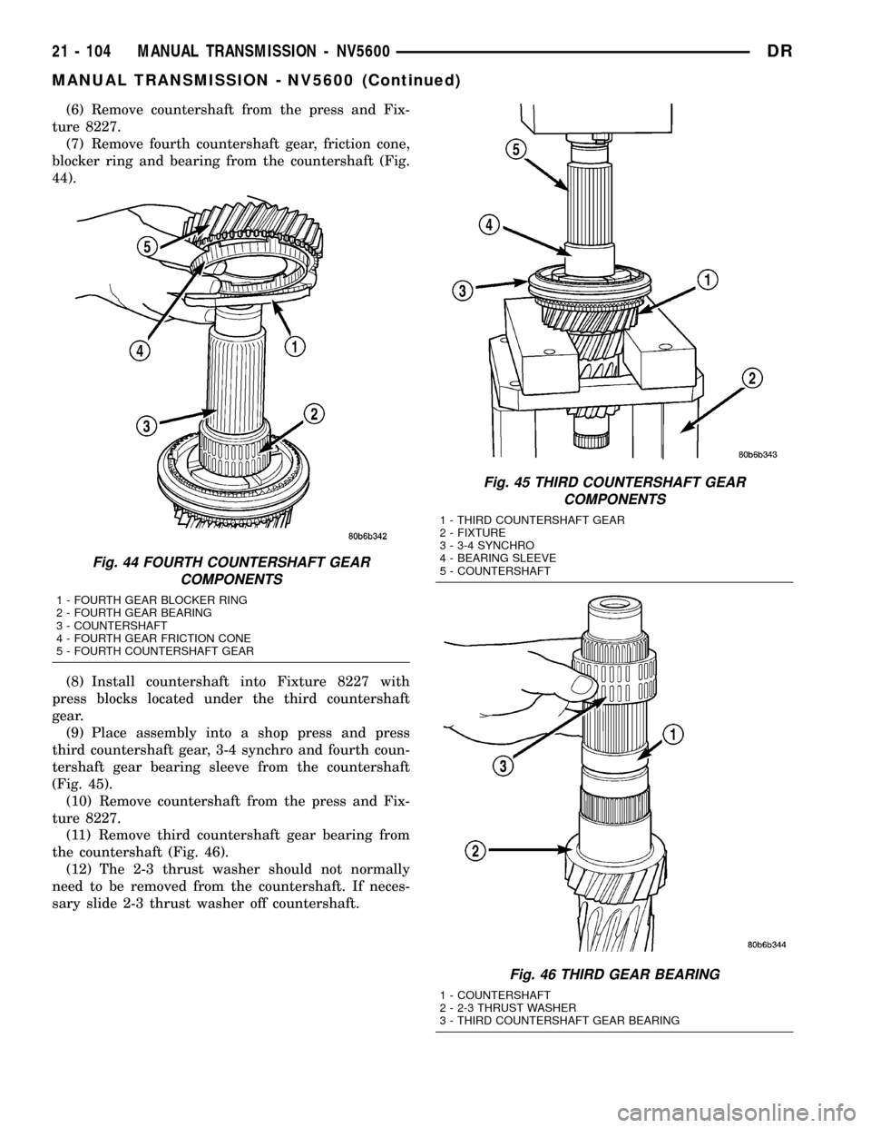
(7) Remove fourth countershaft gear, friction cone,
blocker ring and bearing from the countershaft (Fig.
44).
(8) Install countershaft into Fixture 8227 with
press blocks located under the third countershaft
gear.
(9) Place assembly into a shop press and press
third countershaft gear, 3-4 synchro and fourth coun-
tershaft gear bearing sleeve from the countershaft
(Fig. 45).
(10) Remove countershaft from the press and Fix-
ture 8227.
(11) Remove third countershaft gear bearing from
the countershaft (Fig. 46).
(12) The 2-3 thrust washer should not normally
need to be removed from the countershaft. If neces-
sary slide 2-3 thrust washer off countershaft.
Fig. 44 FOURTH COUNTERSHAFT GEAR
COMPONENTS
1 - FOURTH GEAR BLOCKER RING
2 - FOURTH GEAR BEARING
3 - COUNTERSHAFT
4 - FOURTH GEAR FRICTION CONE
5 - FOURTH COUNTERSHAFT GEAR
Fig. 45 THIRD COUNTERSHAFT GEAR
COMPONENTS
1 - THIRD COUNTERSHAFT GEAR
2 - FIXTURE
3 - 3-4 SYNCHRO
4 - BEARING SLEEVE
5 - COUNTERSHAFT
Fig. 46 THIRD GEAR BEARING
1 - COUNTERSHAFT
2 - 2-3 THRUST WASHER
3 - THIRD COUNTERSHAFT GEAR BEARING
21 - 104 MANUAL TRANSMISSION - NV5600DR
MANUAL TRANSMISSION - NV5600 (Continued)
Page 1808 of 2627
CLUTCH HOUSING
(1) Remove input shaft retainer bolts from the
clutch housing and remove retainer (Fig. 47).
(2) Remove countershaft oil guide from the coun-
tershaft front bearing bore in the clutch housing (Fig.
48).
(3) Remove countershaft front bearing race, end-
play shims and spacer from the clutch housing with
Remover 6061-1 and Handle C-4171 (Fig. 49).
(4) Remove input shaft bearing race with Remover/
Installer 8237 and Handle C-4171.
Fig. 47 INPUT SHAFT RETAINER
1 - INPUT SHAFT RETAINER
2 - CLUTCH HOUSING
Fig. 48 COUNTERSHAFT OIL GUIDE
1 - CLUTCH HOUSING
2 - COUNTERSHAFT OIL GUIDE
Fig. 49 FRONT COUNTERSHAFT BEARING RACE
1 - CLUTCH HOUSING
2 - HANDLE
3 - REMOVER
DRMANUAL TRANSMISSION - NV5600 21 - 105
MANUAL TRANSMISSION - NV5600 (Continued)
Page 1809 of 2627

(5) Remove input shaft oil guide and retainer seal
(Fig. 50).
CLEANING - TRANSMISSION
Clean the gears, bearings shafts, extension/adapter
housing and gear case with solvent. Dry all parts
except the bearings with compressed air. Allow the
bearings to either air dry or wipe them dry with
clean shop towels.
INSPECTION
NOTE: Minor corrosion, nicks, or pitting can be
smoothed with 400 grit emery and polished out with
crocus cloth.
Inspect the reverse idler gear, bearings, shaft and
thrust washers. Replace the bearings if the rollers
are worn, chipped, cracked, flat-spotted or brinnelled.
Replace the gear if the teeth are chipped, cracked or
worn thin.
Inspect the front bearing retainer and bearing cup.
Replace the bearing cup if scored, cracked, brinnelled
or rough. Check the release bearing slide surface of
the retainer carefully. Replace the retainer if worn or
damaged in any way.
Inspect mainshaft bearing surfaces, splines, snap
ring grooves and threads. Replace the shaft if any
surfaces exhibit considerable wear or damage.
Inspect the countershaft and bearings. Replace the
shaft if any surfaces exhibit considerable wear or
damage.Inspect shift forks for wear and distortion. Check
fit of the sleeve in the fork to be sure the two parts
fit and work smoothly. Replace the fork if the roll pin
holes are worn oversize or damaged. Do not attempt
to salvage a worn fork. Replace shift fork roll pins if
necessary or if doubt exists about their condition.
The all bearings for wear, roughness, flat spots,
pitting or other damage. Replace the bearings if nec-
essary.
Inspect the blocker rings and fiction cones. replace
either part if worn or damaged in any way. Replace if
the friction material is burned, flaking off or worn.
Inspect synchro components wear or damage.
Replace parts if worn, cracked or distorted.
Inspect all of the thrust washers and locating pins.
Replace the pins if bent or worn. Replace the wash-
ers if worn or the locating pin notches are distorted.
Inspect the case and housing/adapter sealing and
mating surfaces are free of burrs and nicks. Inspcet
the alignment dowels in the case top surface and in
the housing/adapter are tight and in good condition.
Replace the gear case or housing/adapter if cracked
or broken.
ASSEMBLY
NOTE: Gaskets are not used in the transmission.
Use Mopar Gasket Maker or equivalent on all gear
case and extension housing sealing surfaces.
OUTPUT SHAFT
(1) Place second gear on bench with the synchro
clutch ring up.
(2) Install second gear synchro inner blocker ring
onto second gear (Fig. 51).
Fig. 50 OIL GUIDE AND SEAL
1 - INPUT SHAFT OIL GUIDE
2 - INPUT SHAFT OIL SEAL
Fig. 51 INNER BLOCKER RING
1 - INNER BLOCKER RING
2 - GEAR
21 - 106 MANUAL TRANSMISSION - NV5600DR
MANUAL TRANSMISSION - NV5600 (Continued)
Page 1810 of 2627
(3) Install second gear synchro friction cone over
the blocker ring and onto second gear (Fig. 52).
(4) Install second gear synchro outer blocker ring
over the second gear synchro friction cone. Align one
of the lugs on the outer ring with a lug on the inner
ring (Fig. 53).(5) Install 1-2 synchro assembly onto the second
gear assembly (Fig. 54).
(6) Reverse assembly on the bench.
(7) Lubricate and install second gear bearing into
second gear (Fig. 55).
Fig. 52 FRICTION CONE
1 - GEAR
2 - FRICTION CONE
Fig. 53 OUTER BLOCKER RING
1 - OUTER BLOCKER RING
2 - LUG
3 - GEAR
Fig. 54 3-4 SYNCHRO ASSEMBLY
1 - SYNCHRO
2 - GEAR
Fig. 55 SECOND GEAR AND BEARING
1 - BEARING
2 - GEAR
DRMANUAL TRANSMISSION - NV5600 21 - 107
MANUAL TRANSMISSION - NV5600 (Continued)
Page 1811 of 2627

(8) Place 1-2 synchro, second gear and second gear
bearing assembly on shop press with second gear fac-
ing upward.
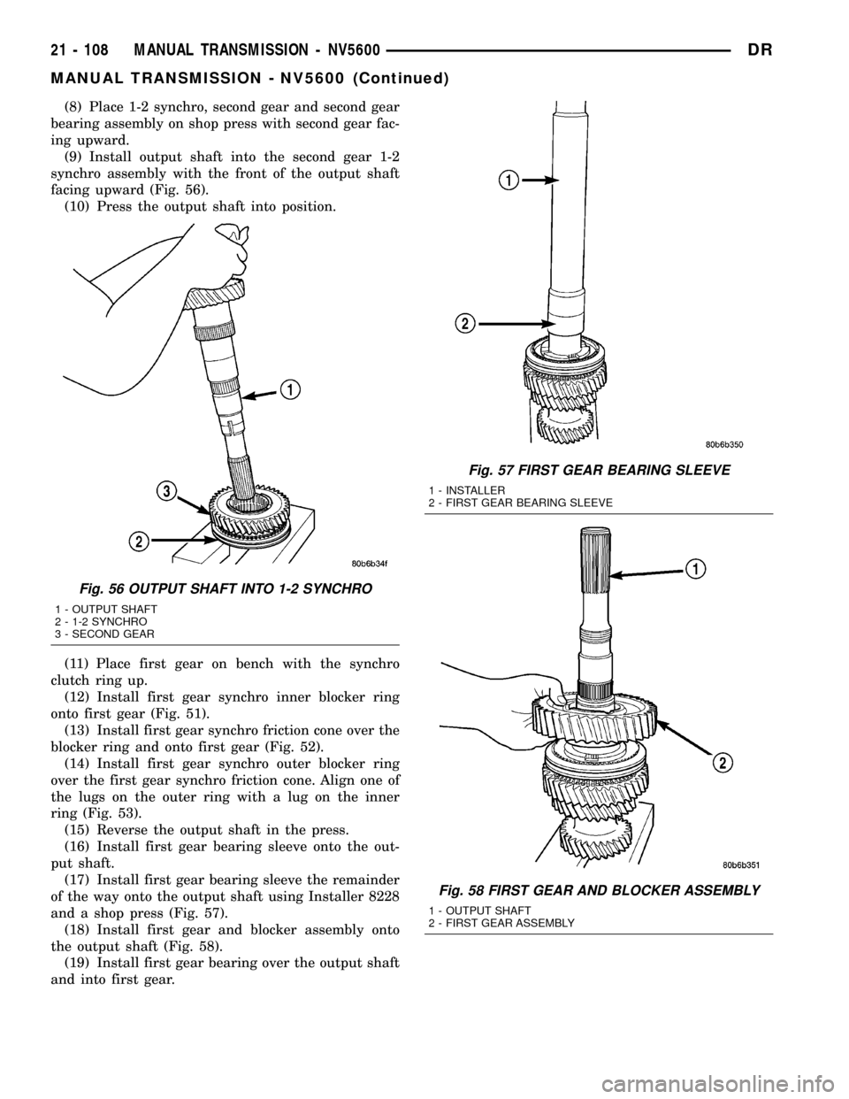
(9) Install output shaft into the second gear 1-2
synchro assembly with the front of the output shaft
facing upward (Fig. 56).
(10) Press the output shaft into position.
(11) Place first gear on bench with the synchro
clutch ring up.
(12) Install first gear synchro inner blocker ring
onto first gear (Fig. 51).
(13) Install first gear synchro friction cone over the
blocker ring and onto first gear (Fig. 52).
(14) Install first gear synchro outer blocker ring
over the first gear synchro friction cone. Align one of
the lugs on the outer ring with a lug on the inner
ring (Fig. 53).
(15) Reverse the output shaft in the press.
(16) Install first gear bearing sleeve onto the out-
put shaft.
(17) Install first gear bearing sleeve the remainder
of the way onto the output shaft using Installer 8228
and a shop press (Fig. 57).
(18) Install first gear and blocker assembly onto
the output shaft (Fig. 58).
(19) Install first gear bearing over the output shaft
and into first gear.
Fig. 56 OUTPUT SHAFT INTO 1-2 SYNCHRO
1 - OUTPUT SHAFT
2 - 1-2 SYNCHRO
3 - SECOND GEAR
Fig. 57 FIRST GEAR BEARING SLEEVE
1 - INSTALLER
2 - FIRST GEAR BEARING SLEEVE
Fig. 58 FIRST GEAR AND BLOCKER ASSEMBLY
1 - OUTPUT SHAFT
2 - FIRST GEAR ASSEMBLY
21 - 108 MANUAL TRANSMISSION - NV5600DR
MANUAL TRANSMISSION - NV5600 (Continued)
Page 1812 of 2627
(20) Install output shaft thrust washer onto the
output shaft (Fig. 59).
(21) Install rear output shaft bearing onto the out-
put shaft with Installer 8228 and a shop press (Fig.
60).
(22) Install anewsnap-ring to hold the rear out-
put bearing onto the output shaft. Install the thick-
est snap-ring which will fit into the groove.
(23) Reverse output shaft in the Fixture 8227 and
support the shaft with press blocks under first gear.
(24) Install sixth gear bearing onto the output
shaft.
(25) Install sixth gear onto the output shaft and
over the sixth gear bearing (Fig. 61).
(26) Install the sixth gear friction cone onto sixth
gear.
Fig. 59 OUTPUT SHAFT THRUST WASHER
1 - OUTPUT SHAFT
2 - OUTPUT SHAFT THRUST WASHER
Fig. 60 REAR OUTPUT SHAFT BEARING
1 - INSTALLER
2 - REAR OUTPUT SHAFT BEARING
Fig. 61 SIXTH GEAR
1 - SIXTH GEAR
2 - SIXTH GEAR BEARING
DRMANUAL TRANSMISSION - NV5600 21 - 109
MANUAL TRANSMISSION - NV5600 (Continued)
Page 1813 of 2627
(27) Install sixth gear blocker ring over the sixth
gear friction cone (Fig. 62).
(28) Install Guide 8235 onto the end of the output
shaft (Fig. 63).(29) Install 5-6 synchro over Guide 8235 and onto
the output shaft.
(30) Press 5-6 synchro (Fig. 64) onto the output
shaft with Installer 8156 and a shop press.
Fig. 62 SIXTH GEAR BLOCKER RING
1 - SIXTH GEAR BLOCKER RING
2 - SIXTH GEAR FRICTION CONE
Fig. 63 OUTPUT SHAFT GUIDE
1 - GUIDE
2 - OUTPUT SHAFT
Fig. 64 5-6 SYNCHRO
1 - INSTALLER
2 - 5-6 SYNCHRO
21 - 110 MANUAL TRANSMISSION - NV5600DR
MANUAL TRANSMISSION - NV5600 (Continued)
Page 1814 of 2627
(31) Install output shaft pocket bearing onto the
output shaft.
(32) Press pocket bearing the remainder of the
way onto the output shaft using Guide 8235 and a
shop press (Fig. 65).
(33) Install anewsnap-ring to hold the output
shaft pocket bearing onto the output shaft.
COUNTERSHAFT
(1) Place third countershaft gear on the bench
with the synchro clutch ring up.
(2) Install third countershaft gear friction cone
onto third gear (Fig. 66).
(3) Install third countershaft gear blocker ring
onto the friction cone (Fig. 67).
Fig. 65 OUTPUT SHAFT POCKET BEARING
1 - GUIDE
2 - POCKET BEARING
Fig. 66 FRICTION CONE AND THIRD GEAR
1 - FRICTION CONE
2 - GEAR
3 - CLUTCH RING
Fig. 67 BLOCKER RING ONTO FRICTION CONE
1 - BLOCKER RING
2 - GEAR
3 - FRICTION CONE
DRMANUAL TRANSMISSION - NV5600 21 - 111
MANUAL TRANSMISSION - NV5600 (Continued)