1998 DODGE RAM 1500 ABS
[x] Cancel search: ABSPage 2167 of 2627
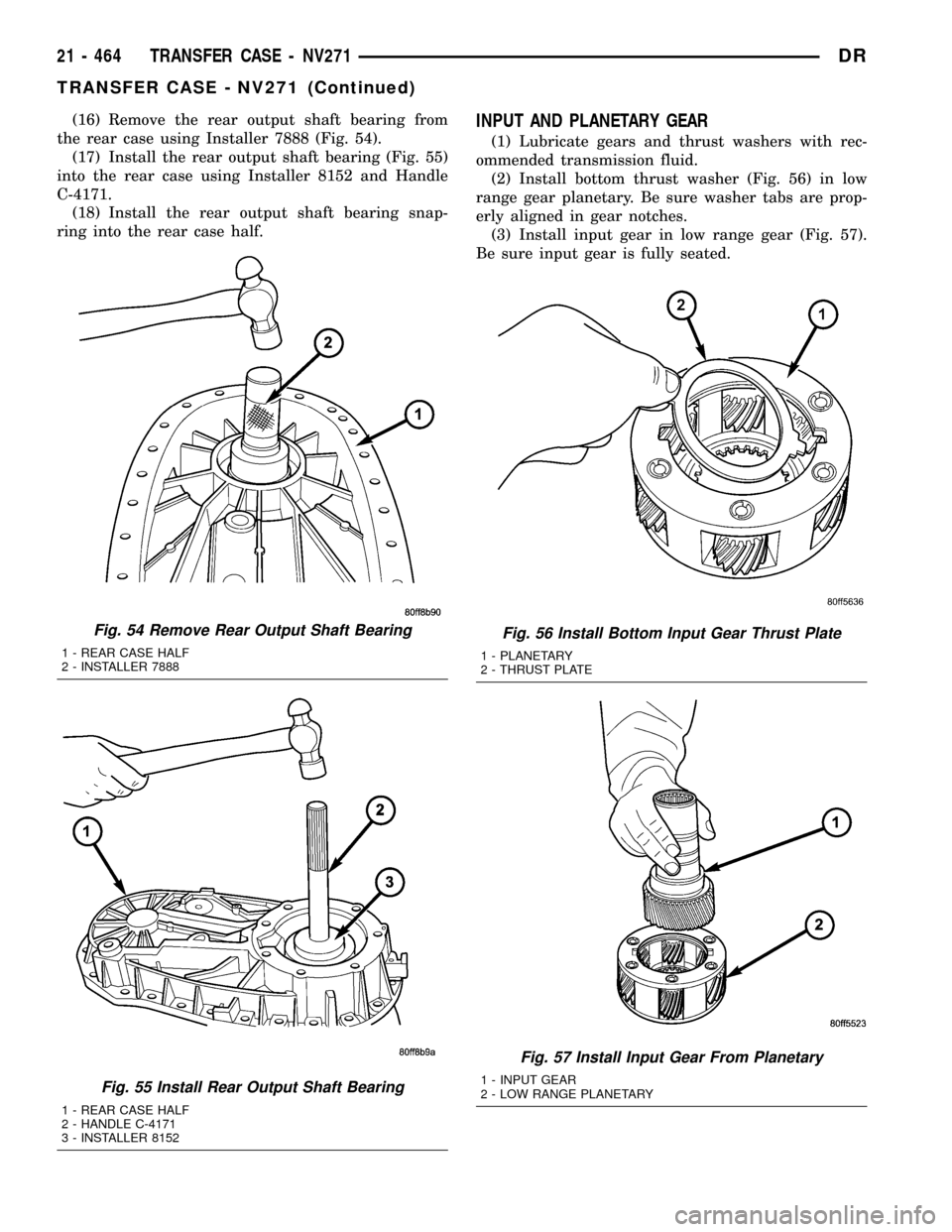
(16) Remove the rear output shaft bearing from
the rear case using Installer 7888 (Fig. 54).
(17) Install the rear output shaft bearing (Fig. 55)
into the rear case using Installer 8152 and Handle
C-4171.
(18) Install the rear output shaft bearing snap-
ring into the rear case half.INPUT AND PLANETARY GEAR
(1) Lubricate gears and thrust washers with rec-
ommended transmission fluid.
(2) Install bottom thrust washer (Fig. 56) in low
range gear planetary. Be sure washer tabs are prop-
erly aligned in gear notches.
(3) Install input gear in low range gear (Fig. 57).
Be sure input gear is fully seated.
Fig. 54 Remove Rear Output Shaft Bearing
1 - REAR CASE HALF
2 - INSTALLER 7888
Fig. 55 Install Rear Output Shaft Bearing
1 - REAR CASE HALF
2 - HANDLE C-4171
3 - INSTALLER 8152
Fig. 56 Install Bottom Input Gear Thrust Plate
1 - PLANETARY
2 - THRUST PLATE
Fig. 57 Install Input Gear From Planetary
1 - INPUT GEAR
2 - LOW RANGE PLANETARY
21 - 464 TRANSFER CASE - NV271DR
TRANSFER CASE - NV271 (Continued)
Page 2201 of 2627
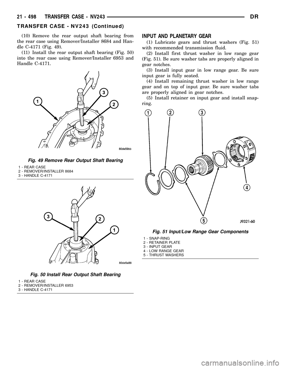
(10) Remove the rear output shaft bearing from
the rear case using Remover/Installer 8684 and Han-
dle C-4171 (Fig. 49).
(11) Install the rear output shaft bearing (Fig. 50)
into the rear case using Remover/Installer 6953 and
Handle C-4171.INPUT AND PLANETARY GEAR
(1) Lubricate gears and thrust washers (Fig. 51)
with recommended transmission fluid.
(2) Install first thrust washer in low range gear
(Fig. 51). Be sure washer tabs are properly aligned in
gear notches.
(3) Install input gear in low range gear. Be sure
input gear is fully seated.
(4) Install remaining thrust washer in low range
gear and on top of input gear. Be sure washer tabs
are properly aligned in gear notches.
(5) Install retainer on input gear and install snap-
ring.
Fig. 49 Remove Rear Output Shaft Bearing
1 - REAR CASE
2 - REMOVER/INSTALLER 8684
3 - HANDLE C-4171
Fig. 50 Install Rear Output Shaft Bearing
1 - REAR CASE
2 - REMOVER/INSTALLER 6953
3 - HANDLE C-4171
Fig. 51 Input/Low Range Gear Components
1 - SNAP-RING
2 - RETAINER PLATE
3 - INPUT GEAR
4 - LOW RANGE GEAR
5 - THRUST WASHERS
21 - 498 TRANSFER CASE - NV243DR
TRANSFER CASE - NV243 (Continued)
Page 2229 of 2627
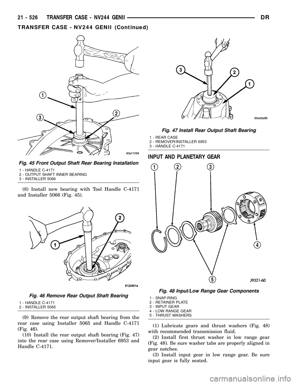
(8) Install new bearing with Tool Handle C-4171
and Installer 5066 (Fig. 45).
(9) Remove the rear output shaft bearing from the
rear case using Installer 5065 and Handle C-4171
(Fig. 46).
(10) Install the rear output shaft bearing (Fig. 47)
into the rear case using Remover/Installer 6953 and
Handle C-4171.
INPUT AND PLANETARY GEAR
(1) Lubricate gears and thrust washers (Fig. 48)
with recommended transmission fluid.
(2) Install first thrust washer in low range gear
(Fig. 48). Be sure washer tabs are properly aligned in
gear notches.
(3) Install input gear in low range gear. Be sure
input gear is fully seated.
Fig. 45 Front Output Shaft Rear Bearing Installation
1 - HANDLE C-4171
2 - OUTPUT SHAFT INNER BEARING
3 - INSTALLER 5066
Fig. 46 Remove Rear Output Shaft Bearing
1 - HANDLE C-4171
2 - INSTALLER 5065
Fig. 47 Install Rear Output Shaft Bearing
1 - REAR CASE
2 - REMOVER/INSTALLER 6953
3 - HANDLE C-4171
Fig. 48 Input/Low Range Gear Components
1 - SNAP-RING
2 - RETAINER PLATE
3 - INPUT GEAR
4 - LOW RANGE GEAR
5 - THRUST WASHERS
21 - 526 TRANSFER CASE - NV244 GENIIDR
TRANSFER CASE - NV244 GENII (Continued)
Page 2230 of 2627
(4) Install remaining thrust washer in low range
gear and on top of input gear. Be sure washer tabs
are properly aligned in gear notches.
(5) Install retainer on input gear and install snap-
ring.
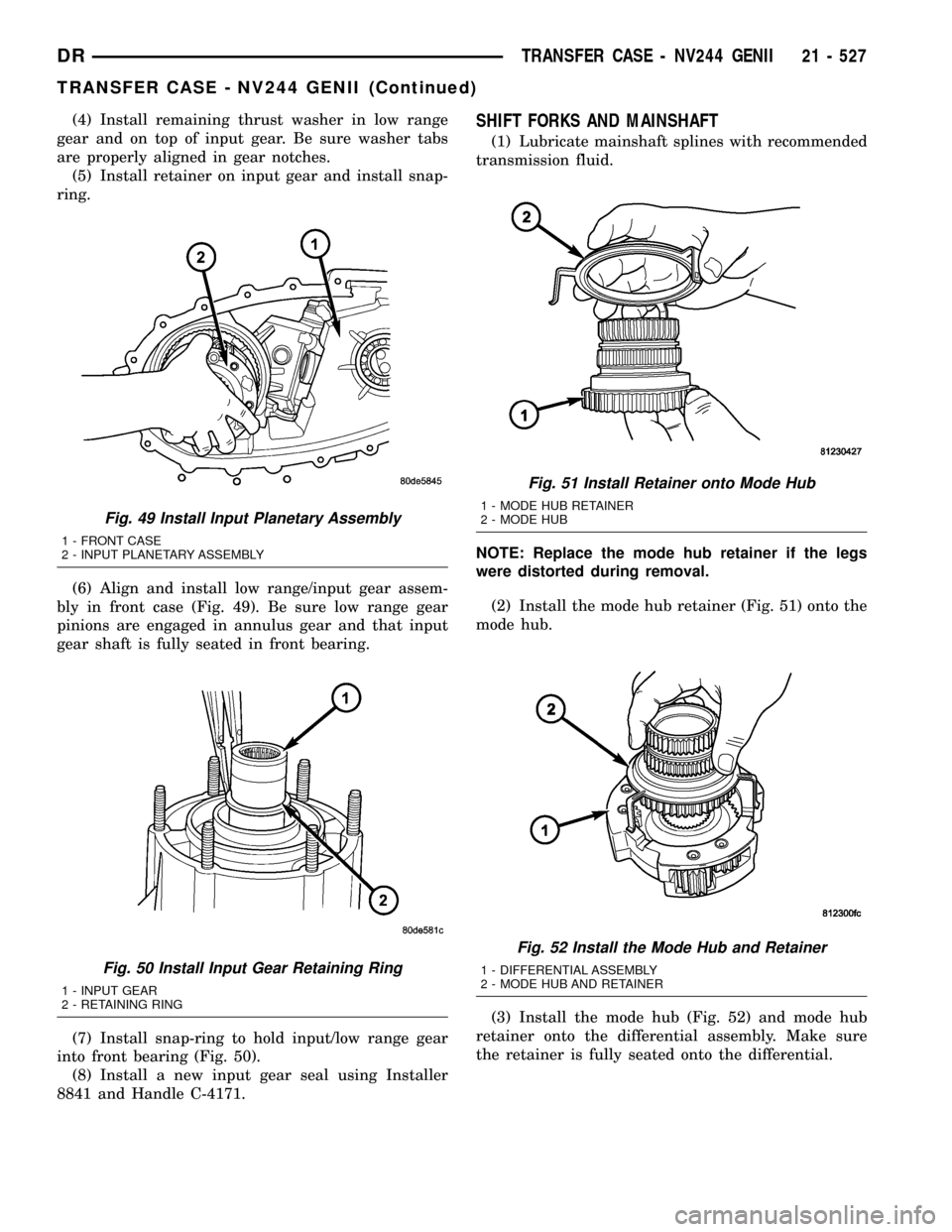
(6) Align and install low range/input gear assem-
bly in front case (Fig. 49). Be sure low range gear
pinions are engaged in annulus gear and that input
gear shaft is fully seated in front bearing.
(7) Install snap-ring to hold input/low range gear
into front bearing (Fig. 50).
(8) Install a new input gear seal using Installer
8841 and Handle C-4171.SHIFT FORKS AND MAINSHAFT
(1) Lubricate mainshaft splines with recommended
transmission fluid.
NOTE: Replace the mode hub retainer if the legs
were distorted during removal.
(2) Install the mode hub retainer (Fig. 51) onto the
mode hub.
(3) Install the mode hub (Fig. 52) and mode hub
retainer onto the differential assembly. Make sure
the retainer is fully seated onto the differential.
Fig. 49 Install Input Planetary Assembly
1 - FRONT CASE
2 - INPUT PLANETARY ASSEMBLY
Fig. 50 Install Input Gear Retaining Ring
1 - INPUT GEAR
2 - RETAINING RING
Fig. 51 Install Retainer onto Mode Hub
1 - MODE HUB RETAINER
2 - MODE HUB
Fig. 52 Install the Mode Hub and Retainer
1 - DIFFERENTIAL ASSEMBLY
2 - MODE HUB AND RETAINER
DRTRANSFER CASE - NV244 GENII 21 - 527
TRANSFER CASE - NV244 GENII (Continued)
Page 2262 of 2627
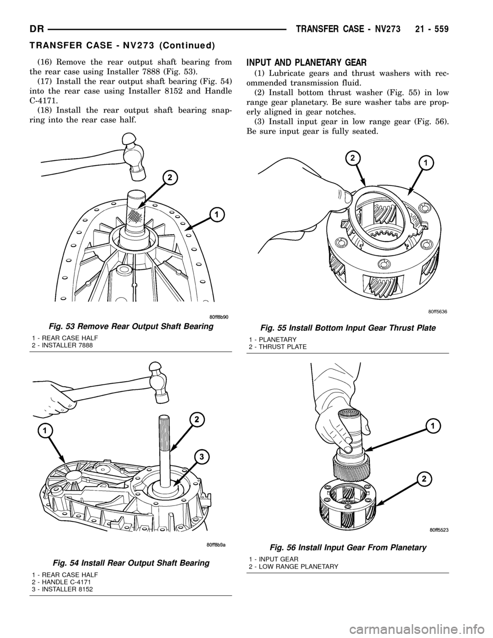
(16) Remove the rear output shaft bearing from
the rear case using Installer 7888 (Fig. 53).
(17) Install the rear output shaft bearing (Fig. 54)
into the rear case using Installer 8152 and Handle
C-4171.
(18) Install the rear output shaft bearing snap-
ring into the rear case half.INPUT AND PLANETARY GEAR
(1) Lubricate gears and thrust washers with rec-
ommended transmission fluid.
(2) Install bottom thrust washer (Fig. 55) in low
range gear planetary. Be sure washer tabs are prop-
erly aligned in gear notches.
(3) Install input gear in low range gear (Fig. 56).
Be sure input gear is fully seated.
Fig. 53 Remove Rear Output Shaft Bearing
1 - REAR CASE HALF
2 - INSTALLER 7888
Fig. 54 Install Rear Output Shaft Bearing
1 - REAR CASE HALF
2 - HANDLE C-4171
3 - INSTALLER 8152
Fig. 55 Install Bottom Input Gear Thrust Plate
1 - PLANETARY
2 - THRUST PLATE
Fig. 56 Install Input Gear From Planetary
1 - INPUT GEAR
2 - LOW RANGE PLANETARY
DRTRANSFER CASE - NV273 21 - 559
TRANSFER CASE - NV273 (Continued)
Page 2298 of 2627

ROAD TESTING WIND NOISE
(1) Drive the vehicle to verify the general location
of the wind noise.
(2) Apply 50 mm (2 in.) masking tape in 150 mm
(6 in.) lengths along weatherstrips, weld seams or
moldings. After each length is applied, drive the vehi-
cle. If noise goes away after a piece of tape is applied,
remove tape, locate, and repair defect.
POSSIBLE CAUSE OF WIND NOISE
²Moldings standing away from body surface can
catch wind and whistle.
²Gaps in sealed areas behind overhanging body
flanges can cause wind-rushing sounds.
²Misaligned movable components.
²Missing or improperly installed plugs in pillars.
²Weld burn through holes.
STANDARD PROCEDURE
STANDARD PROCEDURE - BODY LUBRICATION
All mechanisms and linkages should be lubricated
when necessary. This will maintain ease of operation
and provide protection against rust and excessive
wear. The weatherstrip seals should be lubricated to
prolong their life as well as to improve door sealing.
All applicable exterior and interior vehicle operat-
ing mechanisms should be inspected and cleaned.
Pivot/sliding contact areas on the mechanisms should
then be lubricated.
(1) When necessary, lubricate the operating mech-
anisms with the specified lubricants.
(2) Apply silicone lubricant to a cloth and wipe it
on door seals to avoid over-spray that can soil pas-
senger's clothing.
(3) Before applying lubricant, the component
should be wiped clean. After lubrication, any excess
lubricant should be removed.
(4) The hood latch, latch release mechanism, latch
striker, and safety latch should be lubricated period-
ically.
(5) The door lock cylinders should be lubricated
twice each year (preferably autumn and spring).
²Spray a small amount of lock cylinder lubricant
directly into the lock cylinder.
²Apply a small amount to the key and insert it
into the lock cylinder.
²Rotate it to the locked position and then back to
the unlocked position several times.
²Remove the key. Wipe the lubricant from it with
a clean cloth to avoid soiling of clothing.
STANDARD PROCEDURE - HEAT STAKING
(1) Remove trim panel.(2) Bend or move the trim panel components at
the heat staked joints. Observe the heat staked loca-
tions and/or component seams for looseness.
(3) Heat stake the components.
(a) If the heat staked or component seam loca-
tion is loose, hold the two components tightly
together and using a soldering gun with a flat tip,
melt the material securing the components
together. Do not over heat the affected area, dam-
age to the exterior of the trim panel may occur.
(b) If the heat staked material is broken or miss-
ing, use a hot glue gun to apply new material to
the area to be repaired. The panels that are being
heat staked must be held together while the apply-
ing the glue. Once the new material is in place, it
may be necessary to use a soldering gun to melt
the newly applied material. Do not over heat the
affected area, damage to the exterior of the trim
panel may occur.
(4) Allow the repaired area to cool and verify the
repair.
(5) Install trim panel.
STANDARD PROCEDURE - PLASTIC BODY
PANEL REPAIR
There are many different types of plastics used in
today's automotive environment. We group plastics in
three different categories: Rigid, Semi-Rigid, and
Flexible. Any of these plastics may require the use of
an adhesion promoter for repair. These types of plas-
tic are used extensively on DaimlerChrysler Motors
vehicles. Always follow repair material manufactur-
er's plastic identification and repair procedures.
Rigid Plastics:
Examples of rigid plastic use: Fascias, Hoods,
Doors, and other Body Panels, which include SMC,
ABS, and Polycarbonates.
Semi-Rigid Plastics:
Examples of semi-rigid plastic use: Interior Panels,
Under Hood Panels, and other Body Trim Panels.
Flexible Plastics:
Examples of flexible plastic use: Fascias, Body
Moldings, and upper and lower Fascia Covers.
Repair Procedure:
The repair procedure for all three categories of
plastics is basically the same. The one difference is
the material used for the repair. The materials must
be specific for each substrate, rigid repair material
for rigid plastic repair, semi-rigid repair material for
semi-rigid plastic repair and flexible repair material
for flexible plastic repair.
DRBODY 23 - 3
BODY (Continued)
Page 2299 of 2627
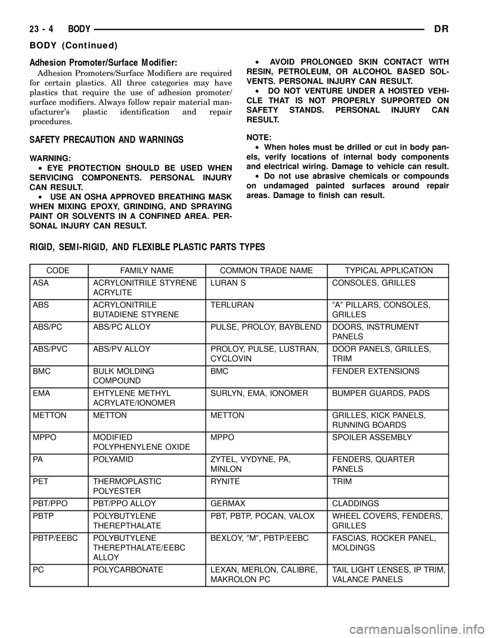
Adhesion Promoter/Surface Modifier:
Adhesion Promoters/Surface Modifiers are required
for certain plastics. All three categories may have
plastics that require the use of adhesion promoter/
surface modifiers. Always follow repair material man-
ufacturer's plastic identification and repair
procedures.
SAFETY PRECAUTION AND WARNINGS
WARNING:
²EYE PROTECTION SHOULD BE USED WHEN
SERVICING COMPONENTS. PERSONAL INJURY
CAN RESULT.
²USE AN OSHA APPROVED BREATHING MASK
WHEN MIXING EPOXY, GRINDING, AND SPRAYING
PAINT OR SOLVENTS IN A CONFINED AREA. PER-
SONAL INJURY CAN RESULT.²AVOID PROLONGED SKIN CONTACT WITH
RESIN, PETROLEUM, OR ALCOHOL BASED SOL-
VENTS. PERSONAL INJURY CAN RESULT.
²DO NOT VENTURE UNDER A HOISTED VEHI-
CLE THAT IS NOT PROPERLY SUPPORTED ON
SAFETY STANDS. PERSONAL INJURY CAN
RESULT.
NOTE:
²When holes must be drilled or cut in body pan-
els, verify locations of internal body components
and electrical wiring. Damage to vehicle can result.
²Do not use abrasive chemicals or compounds
on undamaged painted surfaces around repair
areas. Damage to finish can result.
RIGID, SEMI-RIGID, AND FLEXIBLE PLASTIC PARTS TYPES
CODE FAMILY NAME COMMON TRADE NAME TYPICAL APPLICATION
ASA ACRYLONITRILE STYRENE
ACRYLITELURAN S CONSOLES, GRILLES
ABS ACRYLONITRILE
BUTADIENE STYRENETERLURAN9A9PILLARS, CONSOLES,
GRILLES
ABS/PC ABS/PC ALLOY PULSE, PROLOY, BAYBLEND DOORS, INSTRUMENT
PANELS
ABS/PVC ABS/PV ALLOY PROLOY, PULSE, LUSTRAN,
CYCLOVINDOOR PANELS, GRILLES,
TRIM
BMC BULK MOLDING
COMPOUNDBMC FENDER EXTENSIONS
EMA EHTYLENE METHYL
ACRYLATE/IONOMERSURLYN, EMA, IONOMER BUMPER GUARDS, PADS
METTON METTON METTON GRILLES, KICK PANELS,
RUNNING BOARDS
MPPO MODIFIED
POLYPHENYLENE OXIDEMPPO SPOILER ASSEMBLY
PA POLYAMID ZYTEL, VYDYNE, PA,
MINLONFENDERS, QUARTER
PANELS
PET THERMOPLASTIC
POLYESTERRYNITE TRIM
PBT/PPO PBT/PPO ALLOY GERMAX CLADDINGS
PBTP POLYBUTYLENE
THEREPTHALATEPBT, PBTP, POCAN, VALOX WHEEL COVERS, FENDERS,
GRILLES
PBTP/EEBC POLYBUTYLENE
THEREPTHALATE/EEBC
ALLOYBEXLOY,9M9, PBTP/EEBC FASCIAS, ROCKER PANEL,
MOLDINGS
PC POLYCARBONATE LEXAN, MERLON, CALIBRE,
MAKROLON PCTAIL LIGHT LENSES, IP TRIM,
VALANCE PANELS
23 - 4 BODYDR
BODY (Continued)
Page 2300 of 2627
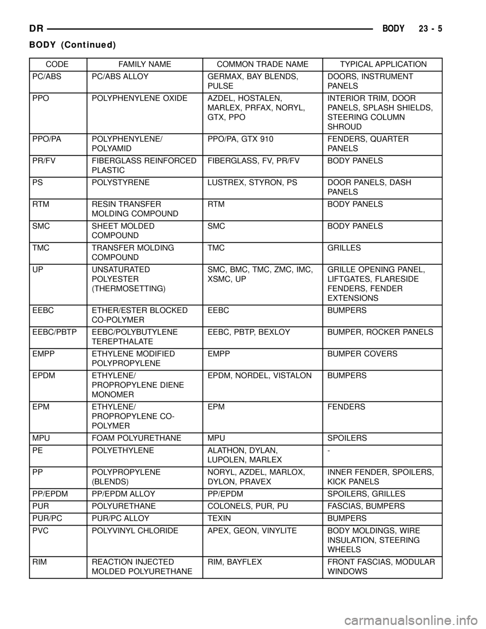
CODE FAMILY NAME COMMON TRADE NAME TYPICAL APPLICATION
PC/ABS PC/ABS ALLOY GERMAX, BAY BLENDS,
PULSEDOORS, INSTRUMENT
PANELS
PPO POLYPHENYLENE OXIDE AZDEL, HOSTALEN,
MARLEX, PRFAX, NORYL,
GTX, PPOINTERIOR TRIM, DOOR
PANELS, SPLASH SHIELDS,
STEERING COLUMN
SHROUD
PPO/PA POLYPHENYLENE/
POLYAMIDPPO/PA, GTX 910 FENDERS, QUARTER
PANELS
PR/FV FIBERGLASS REINFORCED
PLASTICFIBERGLASS, FV, PR/FV BODY PANELS
PS POLYSTYRENE LUSTREX, STYRON, PS DOOR PANELS, DASH
PANELS
RTM RESIN TRANSFER
MOLDING COMPOUNDRTM BODY PANELS
SMC SHEET MOLDED
COMPOUNDSMC BODY PANELS
TMC TRANSFER MOLDING
COMPOUNDTMC GRILLES
UP UNSATURATED
POLYESTER
(THERMOSETTING)SMC, BMC, TMC, ZMC, IMC,
XSMC, UPGRILLE OPENING PANEL,
LIFTGATES, FLARESIDE
FENDERS, FENDER
EXTENSIONS
EEBC ETHER/ESTER BLOCKED
CO-POLYMEREEBC BUMPERS
EEBC/PBTP EEBC/POLYBUTYLENE
TEREPTHALATEEEBC, PBTP, BEXLOY BUMPER, ROCKER PANELS
EMPP ETHYLENE MODIFIED
POLYPROPYLENEEMPP BUMPER COVERS
EPDM ETHYLENE/
PROPROPYLENE DIENE
MONOMEREPDM, NORDEL, VISTALON BUMPERS
EPM ETHYLENE/
PROPROPYLENE CO-
POLYMEREPM FENDERS
MPU FOAM POLYURETHANE MPU SPOILERS
PE POLYETHYLENE ALATHON, DYLAN,
LUPOLEN, MARLEX-
PP POLYPROPYLENE
(BLENDS)NORYL, AZDEL, MARLOX,
DYLON, PRAVEXINNER FENDER, SPOILERS,
KICK PANELS
PP/EPDM PP/EPDM ALLOY PP/EPDM SPOILERS, GRILLES
PUR POLYURETHANE COLONELS, PUR, PU FASCIAS, BUMPERS
PUR/PC PUR/PC ALLOY TEXIN BUMPERS
PVC POLYVINYL CHLORIDE APEX, GEON, VINYLITE BODY MOLDINGS, WIRE
INSULATION, STEERING
WHEELS
RIM REACTION INJECTED
MOLDED POLYURETHANERIM, BAYFLEX FRONT FASCIAS, MODULAR
WINDOWS
DRBODY 23 - 5
BODY (Continued)