1998 DODGE RAM 1500 Fuel filter
[x] Cancel search: Fuel filterPage 29 of 2627

Miles 97,500 100,000 101,250 105,000 108,750 112,500
(Kilometers) (156 000) (160 000) (162 000) (168 000) (174 000) (180 000)
Change engine oil and engine
oil filter.XL²X²XL²X² XL²
Lubricate outer tie rod ends
2500/3500 (4X4) models only.XXX
Flush and replace engine
coolant.X
Inspect drive belt, replace as
required.X
Inspect water pump weep
hole for blockage.X
Replace fuel filter element.
Clean the water in fuel sensor.X
Change rear axle fluid. X
Change front axle fluid (4X4). X
Inspect brake linings. X
Inspect and adjust parking
brake if necessary.X
Miles 116,250 120,000 123,750 127,500 131,250 135,000
(Kilometers) (186 000) (192 000) (198 000) (204 000) (210 000) (216 000)
Change engine oil and engine
oil filter.X² XL²X²XL²X² XL²
Lubricate outer tie rod ends
2500/3500 (4X4) models only.XXX
Clean engine air filter canister.X
Adjust valve lash clearance.X
Inspect drive belts, replace as
required.X
Drain and refill transfer case
fluid (4X4).X
Inspect fan hub. X
Inspect damper. X
Inspect water pump weep
hole for blockage.XX
Replace fuel filter element.
Clean the water in fuel sensor.XX
Inspect front wheel bearings. X
Change rear axle fluid. X X
Change front axle fluid (4X4). X X
Inspect brake linings. X X
Inspect and adjust parking
brake if necessary.XX
Drain and refill automatic
transmission fluid. Replace
filter and adjust bands.X
0 - 16 LUBRICATION & MAINTENANCEDR
MAINTENANCE SCHEDULES (Continued)
Page 30 of 2627

²LTier 1 EPA (250 hp or 305 hp) Engines Only
(see engine data label for your engine type)
²² California LEV (235 hp) Engines Only (see
engine data label for your engine type)Inspection and service should also be performed
anytime a malfunction is observed or suspected.
Schedule ªAº
Miles 7,500 15,000 22,500 30,000 37,500
(Kilometers) (12 000) (24 000) (36 000) (48 000) (60 000)
[Months] [6] [12] [18] [24] [30]
Change engine oil and engine oil filter. X² XL²X²XL²X²
Lubricate outer tie rod ends 2500/3500
(4X4) models only.XXXX X
Check transfer case fluid level (4X4). X
Inspect water pump weep hole for blockage X X
Replace fuel filter element. Clean the water
in fuel sensor.XX
Inspect drive belts, replace as necessary. X
Inspect brake linings. X
Inspect and adjust parking brake if
necessary.X
Inspect fan hub.X
Inspect damper.X
Inspect front wheel bearings. X
Miles 45,000 52,500 60,000 67,500 75,000
(Kilometers) (72 000) (84 000) (96 000) (108 000) (120 000)
[Months] [36] [42] [48] [54] [60]
Change engine oil and engine oil filter. XL²X²XL²X² XL²
Lubricate outer tie rod ends 2500/3500
(4X4) models only.XXXX X
Check transfer case fluid level. X
Flush and replace engine coolant at 60
months, regardless of mileage.X
Inspect drive belts, replace as necessary. X X
Inspect water pump weep hole for blockage X X X
Replace fuel filter element. Clean the water
in fuel sensor.XX
Inspect brake linings. X X
Inspect and adjust parking brake if
necessary.XX
Inspect fan hub. X
Inspect damper. X
Inspect front wheel bearings. X
Replace fuel filter element. Clean the water
in fuel sensorX
DRLUBRICATION & MAINTENANCE 0 - 17
MAINTENANCE SCHEDULES (Continued)
Page 31 of 2627
![DODGE RAM 1500 1998 2.G Workshop Manual Miles 82,500 90,000 97,500 100,000 105,000
(Kilometers) (132 000) (144 000) (156 000) (160 000) (168 000)
[Months] [66] [72] [78] [84]
Change engine oil and engine oil filter. X² XL²X² XL²
Lubrica DODGE RAM 1500 1998 2.G Workshop Manual Miles 82,500 90,000 97,500 100,000 105,000
(Kilometers) (132 000) (144 000) (156 000) (160 000) (168 000)
[Months] [66] [72] [78] [84]
Change engine oil and engine oil filter. X² XL²X² XL²
Lubrica](/manual-img/12/5702/w960_5702-30.png)
Miles 82,500 90,000 97,500 100,000 105,000
(Kilometers) (132 000) (144 000) (156 000) (160 000) (168 000)
[Months] [66] [72] [78] [84]
Change engine oil and engine oil filter. X² XL²X² XL²
Lubricate outer tie rod ends 2500/3500
(4X4) models only.XXXX X
Flush and replace engine coolant, if not
done at 60 mos.X
Check transfer case fluid level (4X4). X
Inspect drive belt, replace as required. X
Inspect fan hub. X
Inspect damper. X
Inspect water pump weep hole for
blockage.XX
Replace fuel filter element. Clean the water
in fuel sensor.XX
Inspect front wheel bearings. X
Inspect brake linings. X
Inspect and adjust parking brake if
necessary.X
Drain and refill automatic transmission fluid.
Replace filter and adjust bands.X
Miles 112,500 120,000 127,500 135,000 142,500 150,000
(Kilometers) (181 000) (193 000) (205 000) (217 000) (229 000) (241 000)
[Months] [90] [96] [102] [108] [114] [150]
Change engine oil and engine
oil filter.X² XL²X²XL²X² XL²
Lubricate outer tie rod ends
2500/3500 (4X4) models only.XXXXX X
Flush and replace engine
coolant, if it has been 160
000 km (100, 000 miles) or 60
months since last change.X
Inspect drive belt, replace as
required.XX
Drain and refill transfer case
fluid (4X4).X
Check tranfer case fluid level
(4X4).X
Inspect fan hub. X X
Inspect damper. X X
Inspect water pump weep
hole for blockage.XXX
Replace fuel filter element.
Clean the water in fuel
sensor.XXX
0 - 18 LUBRICATION & MAINTENANCEDR
MAINTENANCE SCHEDULES (Continued)
Page 394 of 2627

RADIO NOISE SUPPRESSION
GROUND STRAP
DESCRIPTION
Radio noise suppression devices are factory-in-
stalled standard equipment on this vehicle. Radio
Frequency Interference (RFI) and ElectroMagnetic
Interference (EMI) can be produced by any on-board
or external source of electromagnetic energy. These
electromagnetic energy sources can radiate electro-
magnetic signals through the air, or conduct them
through the vehicle electrical system.
When the audio system converts RFI or EMI to an
audible acoustic wave form, it is referred to as radio
noise. This undesirable radio noise is generally man-
ifested in the form of ªbuzzing,º ªhissing,º ªpopping,º
ªclicking,º ªcrackling,º and/or ªwhirringº sounds. In
most cases, RFI and EMI radio noise can be sup-
pressed using a combination of vehicle and compo-
nent grounding, filtering and shielding techniques.
This vehicle is equipped with factory-installed radio
noise suppression devices that were designed to min-
imize exposure to typical sources of RFI and EMI;
thereby, minimizing radio noise complaints.
Factory-installed radio noise suppression is accom-
plished primarily through circuitry or devices that
are integral to the factory-installed radios, audio
power amplifiers and other on-board electrical com-
ponents such as generators, wiper motors, blower
motors, and fuel pumps that have been found to be
potential sources of RFI or EMI. External radio noise
suppression devices that are used on this vehicle to
control RFI or EMI, and can be serviced, include the
following:
²Engine-to-body ground strap- This length of
braided ground strap has an eyelet terminal connec-
tor crimped to each end. One end is secured to the
engine cylinder head(s). The other is secured to the
plenum at the exhaust heat shield forward/outer
attaching stud.
²Resistor-type spark plugs- This type of spark
plug has an internal resistor connected in series
between the spark plug terminal and the center elec-
trode to help reduce the production of electromag-
netic radiation that can result in radio noise.
OPERATION
There are two common strategies that can be used
to suppress Radio Frequency Interference (RFI) and
ElectroMagnetic Interference (EMI) radio noise. The
first suppression strategy involves preventing the
production of RFI and EMI electromagnetic signals
at their sources. The second suppression strategy
involves preventing the reception of RFI and EMIelectromagnetic signals by the audio system compo-
nents.
The use of braided ground straps in key locations
is part of the RFI and EMI prevention strategy.
These ground straps ensure adequate ground paths,
particularly for high current components such as
many of those found in the starting, charging, igni-
tion, engine control and transmission control sys-
tems. An insufficient ground path for any of these
high current components may result in radio noise
caused by induced voltages created as the high cur-
rent seeks alternative ground paths through compo-
nents or circuits intended for use by, or in close
proximity to the audio system components or circuits.
Preventing the reception of RFI and EMI is accom-
plished by ensuring that the audio system compo-
nents are correctly installed in the vehicle. Loose,
corroded or improperly soldered wire harness connec-
tions, improperly routed wiring and inadequate audio
system component grounding can all contribute to
the reception of RFI and EMI. A properly grounded
antenna body and radio chassis, as well as a shielded
antenna coaxial cable with clean and tight connec-
tions will each help reduce the potential for reception
of RFI and EMI.
REMOVAL
BED TO CAB
(1) Disconnect and isolate the battery negative
cable.
(2) Remove the attaching bolts and strap (Fig. 10).
Fig. 10 BED TO CAB GROUND STRAP
1 - BED
2 - CAB
3 - GROUND STRAP
4 - MOUNTING BOLTS
DRAUDIO/VIDEO 8A - 9
Page 411 of 2627

NOTE: ECM Inputs:
²Accelerator Pedal Position Sensor (APPS) Volts
²APPS1 Signal Ð For off engine APPS
²APPS2 Signal Ð For off engine APPS
²APPS idle validation switches #1 and #2
²Battery Temperature
²Battery voltage
²Camshaft Position Sensor (CMP)
²CCD bus (+) circuits
²CCD bus (-) circuits
²Crankshaft Position Sensor (CKP)
²Data link connection for DRB scan tool
²Engine Coolant Temperature (ECT) sensor
²Fuel pressure sensor
²Fan speed (engine cooling fan)
²Ground circuits
²Inlet air temperature sensor/pressure sensor
²Intake air temperature sensor/MAP sensor
²Oil Pressure switch
²Power ground
²Sensor return
²Signal ground
²Water-In-Fuel (WIF) sensor
NOTE: ECM Outputs:
After inputs are received by the ECM, certain sen-
sors, switches and components are controlled or reg-
ulated by the ECM. These are consideredECM
Outputs.These outputs are for:
²CCD bus (+) circuits
²CCD bus (-) circuits
²CKP and APPS outputs to the PCM
²Data link connection for DRB scan tool
²Fan Clutch PWM
²Five volt sensor supply
²Fuel Control Actuator
²Fuel transfer (lift) pump
²Intake manifold air heater relays #1 and #2 con-
trol circuits
²Malfunction indicator lamp (Check engine lamp)
(databus)
²Oil Pressure Swith/warning lamp (databus)
²Wait-to-start warning lamp (databus)
²Water-In-Fuel (WIF) warning lamp (databus)
REMOVAL
The engine control module (ECM) is bolted to a
support bracket near the fuel filter. The support
bracket mounts to the block with four capscrews and
vibration isolators. A ground wire is fastened to the
bracket. The other end of the wire is fastened to the
engine block.
(1) Record any Diagnostic Trouble Codes (DTC's)
found in the ECM.To avoid possible voltage spike damage to the
ECM, ignition key must be off, and both negative
battery cables must be disconnected before unplug-
ging ECM connectors.
(2) Disconnect both negative battery cables at both
batteries.
(3) Remove the 50±way and 60±way connector
bolts at the ECM. Note: The connector bolt is a
female allen head. As bolt is being removed, very
carefully remove connectors from the ECM.
(4) Remove five ECM mounting bolts and remove
ECM from the vehicle (Fig. 2).
INSTALLATION
Do not apply paint to ECM or a poor ground will
result.
(1) Position the ECM to the ECM support bracket
and install the five mounting bolts. Tighten the bolts
to 24 N´m (18 ft. lbs.).
(2) Check pin connectors in ECM, 50±way and
60±way connectors for corrosion or damage. Repair
as necessary.
(3) Clean pins in the 50±way and 60±way electri-
cal connectors with a electrical contact cleaner.
(4) Install the 50±way and 60±way connectors to
ECM. Tighten connector bolts to 3 N´m (27 in. lbs.).
(5) Reconnect both negative battery cables.
(6) Use DRBIIItscan tool to erase any stored com-
panion DTC's from ECM.
Fig. 2 Diesel ECM
1 - ENGINE CONTROL MODULE (ECM)
2 - ECM MOUNTING BOLT
3 - 50-WAY CONNECTOR
4 - SUPPORT PLATE
5 - 60-WAY CONNECTOR
8E - 4 ELECTRONIC CONTROL MODULESDR
ENGINE CONTROL MODULE (Continued)
Page 1227 of 2627

DIAGNOSIS AND TESTING
DIAGNOSIS AND TESTING - ENGINE
DIAGNOSIS - INTRODUCTION
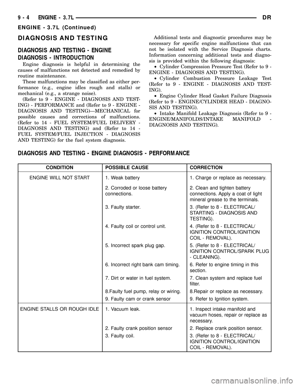
Engine diagnosis is helpful in determining the
causes of malfunctions not detected and remedied by
routine maintenance.
These malfunctions may be classified as either per-
formance (e.g., engine idles rough and stalls) or
mechanical (e.g., a strange noise).
(Refer to 9 - ENGINE - DIAGNOSIS AND TEST-
ING) - PERFORMANCE and (Refer to 9 - ENGINE -
DIAGNOSIS AND TESTING)ÐMECHANICAL for
possible causes and corrections of malfunctions.
(Refer to 14 - FUEL SYSTEM/FUEL DELIVERY -
DIAGNOSIS AND TESTING) and (Refer to 14 -
FUEL SYSTEM/FUEL INJECTION - DIAGNOSIS
AND TESTING) for the fuel system diagnosis.Additional tests and diagnostic procedures may be
necessary for specific engine malfunctions that can
not be isolated with the Service Diagnosis charts.
Information concerning additional tests and diagno-
sis is provided within the following diagnosis:
²Cylinder Compression Pressure Test (Refer to 9 -
ENGINE - DIAGNOSIS AND TESTING).
²Cylinder Combustion Pressure Leakage Test
(Refer to 9 - ENGINE - DIAGNOSIS AND TEST-
ING).
²Engine Cylinder Head Gasket Failure Diagnosis
(Refer to 9 - ENGINE/CYLINDER HEAD - DIAGNO-
SIS AND TESTING).
²Intake Manifold Leakage Diagnosis (Refer to 9 -
ENGINE/MANIFOLDS/INTAKE MANIFOLD -
DIAGNOSIS AND TESTING).
DIAGNOSIS AND TESTING - ENGINE DIAGNOSIS - PERFORMANCE
CONDITION POSSIBLE CAUSE CORRECTION
ENGINE WILL NOT START 1. Weak battery 1. Charge or replace as necessary.
2. Corroded or loose battery
connections.2. Clean and tighten battery
connections. Apply a coat of light
mineral grease to the terminals.
3. Faulty starter. 3. (Refer to 8 - ELECTRICAL/
STARTING - DIAGNOSIS AND
TESTING).
4. Faulty coil or control unit. 4. (Refer to 8 - ELECTRICAL/
IGNITION CONTROL/IGNITION
COIL - REMOVAL).
5. Incorrect spark plug gap. 5. (Refer to 8 - ELECTRICAL/
IGNITION CONTROL/SPARK PLUG
- CLEANING).
6. Incorrect right bank cam timing. 6. Refer to engine timing in this
section.
7. Dirt or water in fuel system. 7. Clean system and replace fuel
filter.
8.Faulty fuel pump, relay or wiring. 8.Repair or replace as necessary.
9. Faulty cam or crank sensor 9. Refer to Ignition system.
ENGINE STALLS OR ROUGH IDLE 1. Vacuum leak. 1. Inspect intake manifold and
vacuum hoses, repair or replace as
necessary.
2. Faulty crank position sensor 2. Replace crank position sensor.
3. Faulty coil. 3. (Refer to 8 - ELECTRICAL/
IGNITION CONTROL/IGNITION
COIL - REMOVAL).
9 - 4 ENGINE - 3.7LDR
ENGINE - 3.7L (Continued)
Page 1228 of 2627

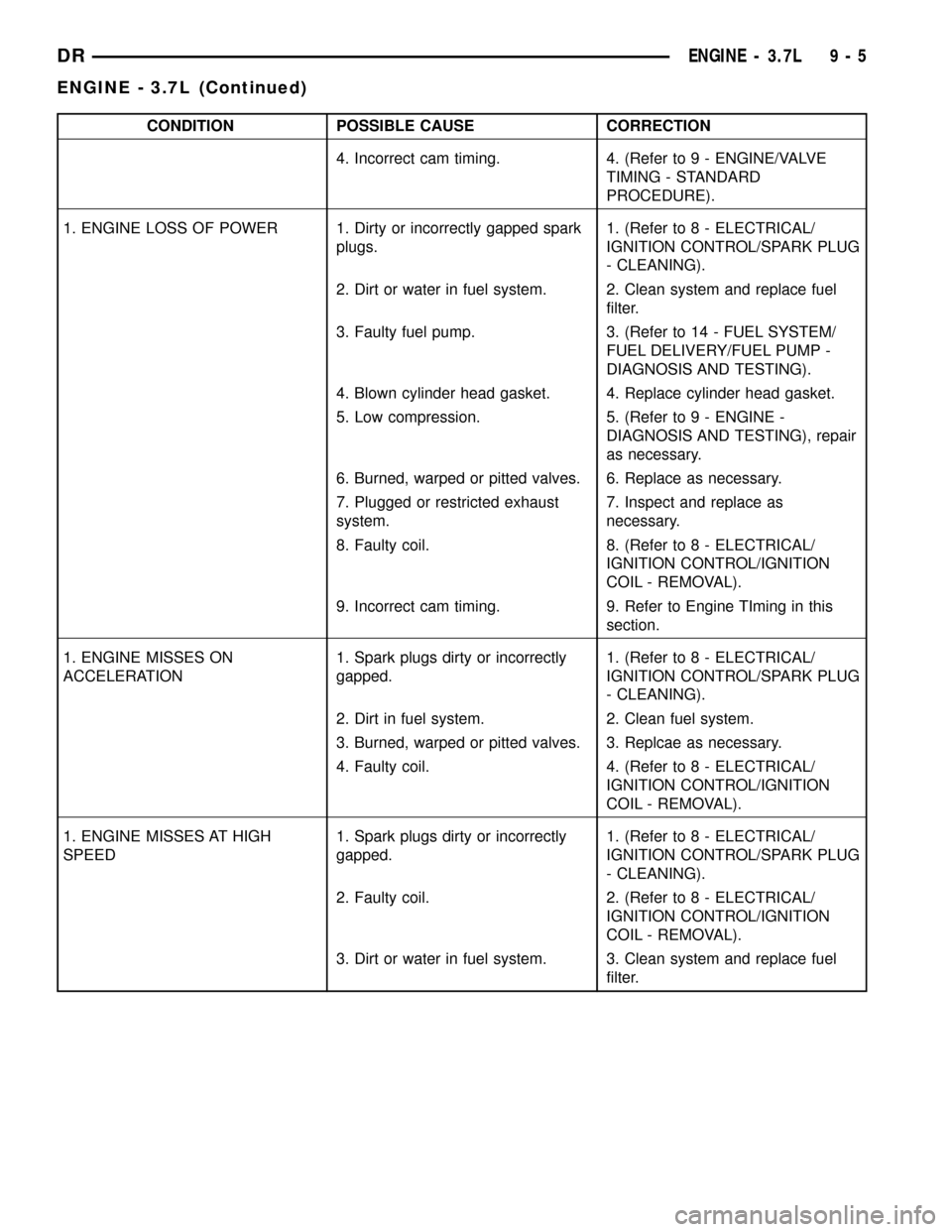
CONDITION POSSIBLE CAUSE CORRECTION
4. Incorrect cam timing. 4. (Refer to 9 - ENGINE/VALVE
TIMING - STANDARD
PROCEDURE).
1. ENGINE LOSS OF POWER 1. Dirty or incorrectly gapped spark
plugs.1. (Refer to 8 - ELECTRICAL/
IGNITION CONTROL/SPARK PLUG
- CLEANING).
2. Dirt or water in fuel system. 2. Clean system and replace fuel
filter.
3. Faulty fuel pump. 3. (Refer to 14 - FUEL SYSTEM/
FUEL DELIVERY/FUEL PUMP -
DIAGNOSIS AND TESTING).
4. Blown cylinder head gasket. 4. Replace cylinder head gasket.
5. Low compression. 5. (Refer to 9 - ENGINE -
DIAGNOSIS AND TESTING), repair
as necessary.
6. Burned, warped or pitted valves. 6. Replace as necessary.
7. Plugged or restricted exhaust
system.7. Inspect and replace as
necessary.
8. Faulty coil. 8. (Refer to 8 - ELECTRICAL/
IGNITION CONTROL/IGNITION
COIL - REMOVAL).
9. Incorrect cam timing. 9. Refer to Engine TIming in this
section.
1. ENGINE MISSES ON
ACCELERATION1. Spark plugs dirty or incorrectly
gapped.1. (Refer to 8 - ELECTRICAL/
IGNITION CONTROL/SPARK PLUG
- CLEANING).
2. Dirt in fuel system. 2. Clean fuel system.
3. Burned, warped or pitted valves. 3. Replcae as necessary.
4. Faulty coil. 4. (Refer to 8 - ELECTRICAL/
IGNITION CONTROL/IGNITION
COIL - REMOVAL).
1. ENGINE MISSES AT HIGH
SPEED1. Spark plugs dirty or incorrectly
gapped.1. (Refer to 8 - ELECTRICAL/
IGNITION CONTROL/SPARK PLUG
- CLEANING).
2. Faulty coil. 2. (Refer to 8 - ELECTRICAL/
IGNITION CONTROL/IGNITION
COIL - REMOVAL).
3. Dirt or water in fuel system. 3. Clean system and replace fuel
filter.
DRENGINE - 3.7L 9 - 5
ENGINE - 3.7L (Continued)
Page 1244 of 2627

AIR CLEANER ELEMENT
REMOVAL
Filter Element Only
Housing removal is not necessary for element (fil-
ter) replacement.
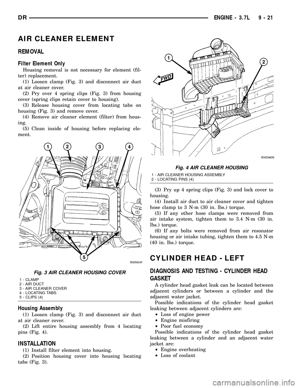
(1) Loosen clamp (Fig. 3) and disconnect air duct
at air cleaner cover.
(2) Pry over 4 spring clips (Fig. 3) from housing
cover (spring clips retain cover to housing).
(3) Release housing cover from locating tabs on
housing (Fig. 3) and remove cover.
(4) Remove air cleaner element (filter) from hous-
ing.
(5) Clean inside of housing before replacing ele-
ment.
Housing Assembly
(1) Loosen clamp (Fig. 3) and disconnect air duct
at air cleaner cover.
(2) Lift entire housing assembly from 4 locating
pins (Fig. 4).
INSTALLATION
(1) Install filter element into housing.
(2) Position housing cover into housing locating
tabs (Fig. 3).(3) Pry up 4 spring clips (Fig. 3) and lock cover to
housing.
(4) Install air duct to air cleaner cover and tighten
hose clamp to 3 N´m (30 in. lbs.) torque.
(5) If any other hose clamps were removed from
air intake system, tighten them to 3.4 N´m (30 in.
lbs.) torque.
(6) If any bolts were removed from air resonator
housing or air intake tubing, tighten them to 4.5 N´m
(40 in. lbs.) torque.
CYLINDER HEAD - LEFT
DIAGNOSIS AND TESTING - CYLINDER HEAD
GASKET
A cylinder head gasket leak can be located between
adjacent cylinders or between a cylinder and the
adjacent water jacket.
Possible indications of the cylinder head gasket
leaking between adjacent cylinders are:
²Loss of engine power
²Engine misfiring
²Poor fuel economy
Possible indications of the cylinder head gasket
leaking between a cylinder and an adjacent water
jacket are:
²Engine overheating
²Loss of coolant
Fig. 3 AIR CLEANER HOUSING COVER
1 - CLAMP
2 - AIR DUCT
3 - AIR CLEANER COVER
4 - LOCATING TABS
5 - CLIPS (4)
Fig. 4 AIR CLEANER HOUSING
1 - AIR CLEANER HOUSING ASSEMBLY
2 - LOCATING PINS (4)
DRENGINE - 3.7L 9 - 21