1998 DODGE RAM 1500 Fuel filter
[x] Cancel search: Fuel filterPage 1474 of 2627
(32) Disconnect fuel heater, water in fuel sensor,
and fuel lift pump connectors.
(33) Remove the fuel filter assembly-to-cylinder
head bolts and remove filter assembly from vehicle.
(34) Remove wire harness P-clip from cylinder
head (located behind filter housing).
(35) Remove the cylinder head cover(Refer to 9 -
ENGINE/CYLINDER HEAD/CYLINDER HEAD
COVER(S) - REMOVAL).
(36) Disconnect rocker housing injector harness
connectors.
(37) Remove injector harness nuts from injectors.
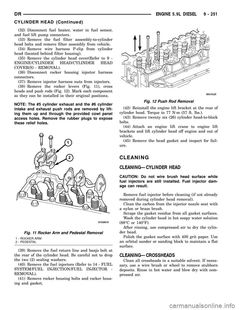
(38) Remove the rocker levers (Fig. 11), cross
heads and push rods (Fig. 12). Mark each component
so they can be installed in their original positions.
NOTE: The #5 cylinder exhaust and the #6 cylinder
intake and exhaust push rods are removed by lift-
ing them up and through the provided cowl panel
access holes. Remove the rubber plugs to expose
these relief holes.
(39) Remove the fuel return line and banjo bolt at
the rear of the cylinder head. Be careful not to drop
the two (2) sealing washers.
(40) Remove the fuel injectors (Refer to 14 - FUEL
SYSTEM/FUEL INJECTION/FUEL INJECTOR -
REMOVAL).
(41) Remove rocker housing bolts and rocker hous-
ing and gasket.(42) Reinstall the engine lift bracket at the rear of
cylinder head. Torque to 77 N´m (57 ft. lbs.).
(43) Remove twenty six (26) cylinder head-to-block
bolts.
(44) Attach an engine lift crane to engine lift
brackets and lift cylinder head off engine and out of
vehicle.
(45) Remove the head gasket and inspect for fail-
ure.
CLEANING
CLEANINGÐCYLINDER HEAD
CAUTION: Do not wire brush head surface while
fuel injectors are still installed. Fuel injector dam-
age can result.
Remove fuel injector before cleaning (if not already
removed during cylinder head removal).
Clean the carbon from the injector nozzle seat with
a nylon or brass brush.
Scrape the gasket residue from all gasket surfaces.
Wash the cylinder head in hot soapy water solution
(88ÉC or 140ÉF).
After rinsing, use compressed air to dry the cylin-
der head.
Polish the gasket surface with 400 grit paper. Use
an orbital sander or sanding block to maintain a flat
surface.
CLEANINGÐCROSSHEADS
Clean all crossheads in a suitable solvent. If neces-
sary, use a wire brush or wheel to remove stubborn
deposits. Rinse in hot water and blow dry with com-
pressed air.
Fig. 11 Rocker Arm and Pedestal Removal
1 - ROCKER ARM
2 - PEDESTAL
Fig. 12 Push Rod Removal
DRENGINE 5.9L DIESEL 9 - 251
CYLINDER HEAD (Continued)
Page 1477 of 2627
(9) Install rocker housing and bolts. Tighten to 24
Nm (18 lb. ft.).
(10) Install fuel injector(Refer to 14 - FUEL SYS-
TEM/FUEL INJECTION/FUEL INJECTOR -
INSTALLATION).
(11) Install injector harness nuts. Tighten to 1.25
Nm (11 lb. in.).
(12) Install cylinder head cover (Refer to 9 -
ENGINE/CYLINDER HEAD/CYLINDER HEAD
COVER(S) - INSTALLATION).
(13) Install wire harness P-clip to cylinder head
behind filter housing 24 N´m (18 ft. lbs.).
(14) Connect the IAT/MAP sensor connector.
(15) Install the fuel filter canister assembly and
torque mounting bolts to 24 N´m (18 ft. lbs.).
(16) Connect fuel lift pump, WIF sensor, and fuel
heater.
(17) Remove the engine lift bracket at rear of cyl-
inder head.
CAUTION: Failure to follow procedure will result in
fuel leaks and/or fuel system failure.
(18)Install the fuel rail and high pressure
fuel lines as follows:
(a) Hand tighten fuel rail bolts.
(b) Hand tighten fuel drain line to pressure lim-
iting valve. Hand tighten banjo bolt at fuel filter
housing.
(c) Hand tighten fuel rail-to-cylinder head high
pressure fuel lines.(d) Install fuel line brace bolts-to-intake mani-
fold finger tight.
(e) Hand tighten fuel pump to fuel rail line.
(f) Torque fuel line nuts at cylinder head to 30
Nm ( 22 ft. lbs.).
(g) Torque fuel line nuts at fuel rail to 30 Nm
(22 ft. lbs.)
(h) Using a back up wrench, torque fuel pump to
fuel rail line to 37 Nm (27 ft. lbs.). At injection
pump.
(i) Torque fuel pump to fuel rail line to 37 Nm
(27 ft. lbs.) at fuel rail.
(j) Torque fuel drain banjo bolt at pressure lim-
iting valve and front of fuel filter housing to 24 Nm
(18 ft. lbs.).
(k) Torque fuel line brace bolts to 24 N´m (18 ft.
lbs.).
(l) Torque rail bolts to 24 Nm (18 ft. lbs.).
(m) Connect fuel pressure sensor.
(19) Install the engine lift bracket at the rear of
cylinder head. Torque to 77 N´m (57 ft. lbs.).
(20) Reposition number 6 fuel line shield and
torque to 43 N´m (32 ft. lbs.).
(21) Install the fuel filter to injection pump low
pressure line. Inspect and replace sealing washers if
necessary. Torque banjo bolts to 24 N´m (18 ft. lbs.).
(22) Connect fuel return line at back of cylinder
head hand tight.
(23) Connect fuel return line at filter housing hand
tight.
(24) Torque banjo connections at cylinder head and
fuel filter housing to 24 Nm (18 ft. lbs.)
(25) Install bracket to rear of filter housing.
Torque to 24 Nm (18 ft. lbs.).
(26) Using new gaskets, install the intake grid
heater and air inlet housing. Torque bolts to 24 N´m
(18 ft. lbs.).
(27) Install wire harness P-clip and push on clip to
air inlet housing.
(28) Connect engine oil level indicator tube at fuel
filter housing and at air inlet housing.
(29) Connect the APPS connector.
(30) Install the APPS assembly to the cylinder
head bracket and torque bolts to 24 N´m (18 ft. lbs.).
(31) Install the throttle linkage cover.
(32) Install the charge air cooler-to-air inlet hous-
ing duct assembly. Torque all clamps to 11 N´m (100
in. lbs.).
(33) Connect intake grid heater wires.
(34) Secure engine harness to front of cylinder
head with bolt at four locations.
(35) Connect engine coolant temperature sensor
connector.
(36) Connect radiator upper hose to thermostat
housing.
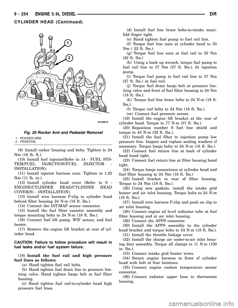
Fig. 20 Rocker Arm and Pedestal Removal
1 - ROCKER ARM
2 - PEDESTAL
9 - 254 ENGINE 5.9L DIESELDR
CYLINDER HEAD (Continued)
Page 1515 of 2627
OIL
STANDARD PROCEDURE
STANDARD PROCEDURE - ENGINE OIL LEVEL
CAUTION: Do not overfill crankcase with engine oil,
oil foaming and oil pressure loss can result.
To ensure proper lubrication of an engine, the
engine oil must be maintained at an acceptable level.
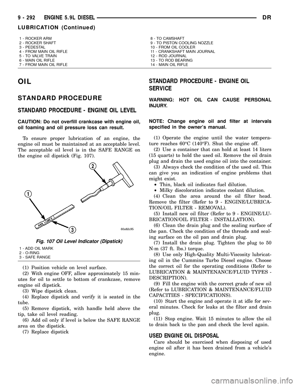
The acceptable oil level is in the SAFE RANGE on
the engine oil dipstick (Fig. 107).
(1) Position vehicle on level surface.
(2) With engine OFF, allow approximately 15 min-
utes for oil to settle to bottom of crankcase, remove
engine oil dipstick.
(3) Wipe dipstick clean.
(4) Replace dipstick and verify it is seated in the
tube.
(5) Remove dipstick, with handle held above the
tip, take oil level reading.
(6) Add oil only if level is below the SAFE RANGE
area on the dipstick.
(7) Replace dipstick
STANDARD PROCEDURE - ENGINE OIL
SERVICE
WARNING: HOT OIL CAN CAUSE PERSONAL
INJURY.
NOTE: Change engine oil and filter at intervals
specified in the owner's manual.
(1) Operate the engine until the water tempera-
ture reaches 60ÉC (140ÉF). Shut the engine off.
(2) Use a container that can hold at least 14 liters
(15 quarts) to hold the used oil. Remove the oil drain
plug and drain the used engine oil into the container.
(3) Always check the condition of the used oil. This
can give you an indication of engine problems that
might exist.
²Thin, black oil indicates fuel dilution.
²Milky discoloration indicates coolant dilution.
(4) Clean the area around the oil filter head.
Remove the filter (Refer to 9 - ENGINE/LUBRICA-
TION/OIL FILTER - REMOVAL).
(5) Install new oil filter (Refer to 9 - ENGINE/LU-
BRICATION/OIL FILTER - INSTALLATION).
(6) Clean the drain plug and the sealing surface of
the pan. Check the condition of the threads and seal-
ing surface on the oil pan and drain plug.
(7) Install the drain plug. Tighten the plug to 50
N´m (37 ft. lbs.) torque.
(8) Use only High-Quality Multi-Viscosity lubricat-
ing oil in the Cummins Turbo Diesel engine. Choose
the correct oil for the operating conditions (Refer to
LUBRICATION & MAINTENANCE/FLUID TYPES -
DESCRIPTION).
(9) Fill the engine with the correct grade of new oil
(Refer to LUBRICATION & MAINTENANCE/FLUID
CAPACITIES - SPECIFICATIONS).
(10) Start the engine and operate it at idle for sev-
eral minutes. Check for leaks at the filter and drain
plug.
(11) Stop engine. Wait 15 minutes to allow the oil
to drain back to the pan and check the level again.
USED ENGINE OIL DISPOSAL
Care should be exercised when disposing of used
engine oil after it has been drained from a vehicle's
engine.
1 - ROCKER ARM
2 - ROCKER SHAFT
3 - PEDESTAL
4 - FROM MAIN OIL RIFLE
5 - TO VALVE TRAIN
6 - MAIN OIL RIFLE
7 - FROM MAIN OIL RIFLE8 - TO CAMSHAFT
9 - TO PISTON COOLING NOZZLE
10 - FROM OIL COOLER
11 - CRANKSHAFT MAIN JOURNAL
12 - ROD JOURNAL
13 - TO ROD BEARING
14 - MAIN OIL RIFLE
Fig. 107 Oil Level Indicator (Dipstick)
1 - ADD OIL MARK
2 - O-RING
3 - SAFE RANGE
9 - 292 ENGINE 5.9L DIESELDR
LUBRICATION (Continued)
Page 1520 of 2627
(13) Install the cooling fan (Refer to 7 - COOLING/
ENGINE/RADIATOR FAN - INSTALLATION).
(14) Connect battery negative cables.
(15) Start engine and check for oil leaks.
INTAKE MANIFOLD
REMOVAL
(1) Disconnect the battery negative cables.
(2) Remove the charge air cooler outlet tube from
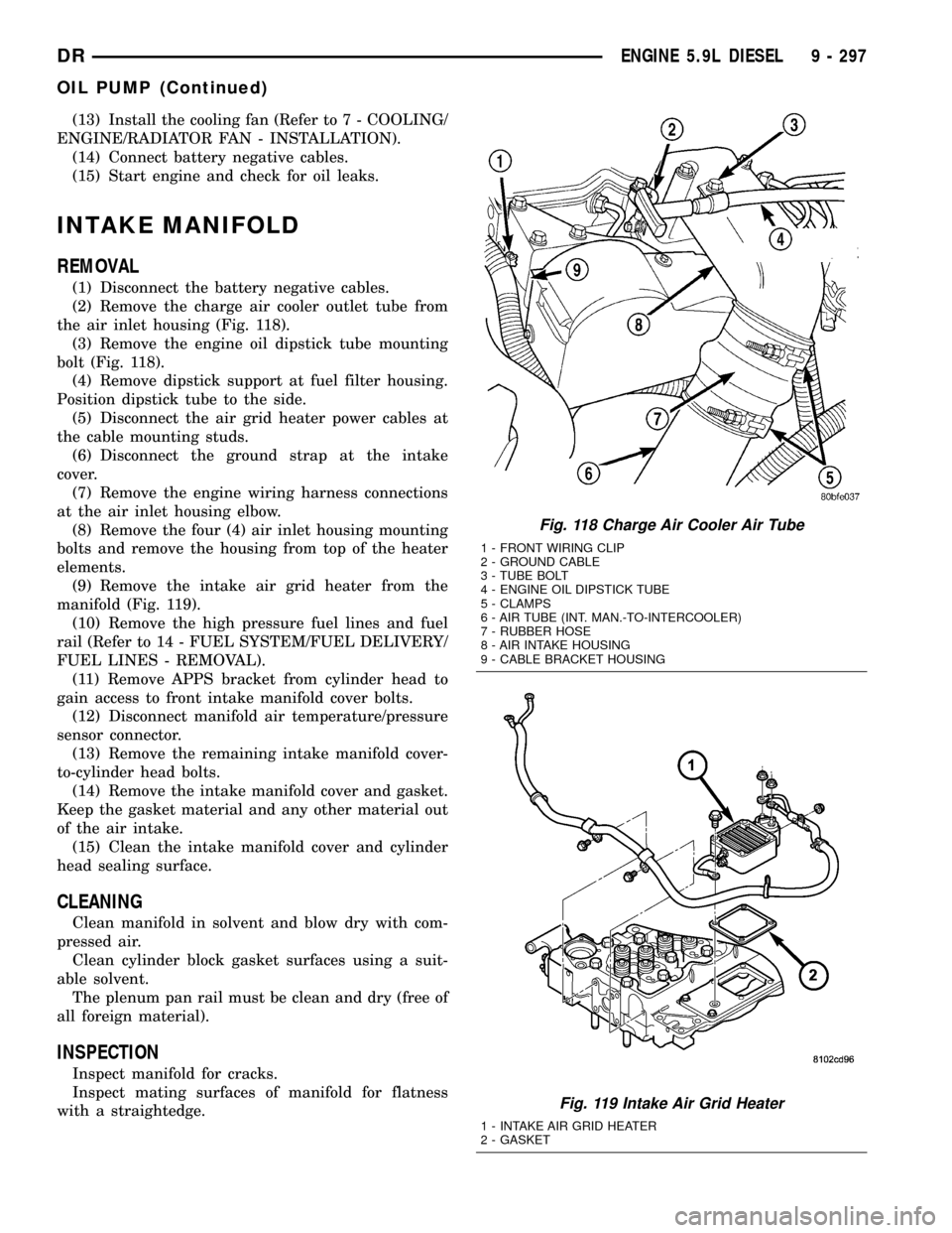
the air inlet housing (Fig. 118).
(3) Remove the engine oil dipstick tube mounting
bolt (Fig. 118).
(4) Remove dipstick support at fuel filter housing.
Position dipstick tube to the side.
(5) Disconnect the air grid heater power cables at
the cable mounting studs.
(6) Disconnect the ground strap at the intake
cover.
(7) Remove the engine wiring harness connections
at the air inlet housing elbow.
(8) Remove the four (4) air inlet housing mounting
bolts and remove the housing from top of the heater
elements.
(9) Remove the intake air grid heater from the
manifold (Fig. 119).
(10) Remove the high pressure fuel lines and fuel
rail (Refer to 14 - FUEL SYSTEM/FUEL DELIVERY/
FUEL LINES - REMOVAL).
(11) Remove APPS bracket from cylinder head to
gain access to front intake manifold cover bolts.
(12) Disconnect manifold air temperature/pressure
sensor connector.
(13) Remove the remaining intake manifold cover-
to-cylinder head bolts.
(14) Remove the intake manifold cover and gasket.
Keep the gasket material and any other material out
of the air intake.
(15) Clean the intake manifold cover and cylinder
head sealing surface.
CLEANING
Clean manifold in solvent and blow dry with com-
pressed air.
Clean cylinder block gasket surfaces using a suit-
able solvent.
The plenum pan rail must be clean and dry (free of
all foreign material).
INSPECTION
Inspect manifold for cracks.
Inspect mating surfaces of manifold for flatness
with a straightedge.
Fig. 118 Charge Air Cooler Air Tube
1 - FRONT WIRING CLIP
2 - GROUND CABLE
3 - TUBE BOLT
4 - ENGINE OIL DIPSTICK TUBE
5 - CLAMPS
6 - AIR TUBE (INT. MAN.-TO-INTERCOOLER)
7 - RUBBER HOSE
8 - AIR INTAKE HOUSING
9 - CABLE BRACKET HOUSING
Fig. 119 Intake Air Grid Heater
1 - INTAKE AIR GRID HEATER
2 - GASKET
DRENGINE 5.9L DIESEL 9 - 297
OIL PUMP (Continued)
Page 1521 of 2627
INSTALLATION
(1) Using a new gasket, install the intake manifold
cover.
(2) Install the cover-to-cylinder head bolts that do
not hold down the fuel rail. Tighten the bolts to 24
N´m (18 ft. lbs.) torque.
(3) Install the high pressure rail and fuel lines
(Refer to 14 - FUEL SYSTEM/FUEL DELIVERY/
FUEL LINES - INSTALLATION).
(4) Using two (2) new gaskets, install the intake
air grid heater and air inlet housing. Position the
ground cable and install and tighten the bolts to 24
N´m (18 ft. lbs.) torque.
(5) Connect the manifold air temperature/pressure
sensor connector.
(6) Install and tighten the air intake heater power
supply nuts to 14 N´m (120 in. lbs.) torque.
(7) Install the APPS bracket. Torque fasteners to
43 N´m (32ft lbs.) torque.
(8) Install oil dipstick tube support at fuel filter
housing.
(9) Install the engine oil dipstick tube and mount-
ing bolt.
(10) Position the charge air cooler outlet tube onto
the air inlet housing. Tighten the clamps to 11 N´m
(100 in. lbs.) torque.
(11) Attach the engine wire harness to the air inlet
housing at two locations.
(12) Prime the fuel system. Refer to the fuel prim-
ing procedure in Group 14, Fuel System.
(13) Connect the battery negative cables.
EXHAUST MANIFOLD
REMOVAL
(1) Disconnect the battery negative cables.
(2) Raise vehicle on hoist.
(3) Disconnect the exhaust pipe from the turbo-
charger elbow.
(4) Disconnect oil drain tube from turbocharger.
(5) Lower vehicle.
(6) Disconnect the turbocharger air inlet hose.
(7) Remove air cleaner assembly.
(8) Disconnect the turbocharger oil supply line.
(9) Disconnect the charge air cooler inlet pipe from
the turbocharger.
(10) Remove the turbocharger and gasket from the
exhaust manifold.
(11) Remove the cab heater return pipe nuts from
the exhaust manifold stud. Position the tube out of
the way.
(12) Remove heat shield.
(13) Remove exhaust manifold bolt lockplates.
(14) Remove the exhaust manifold-to-cylinder head
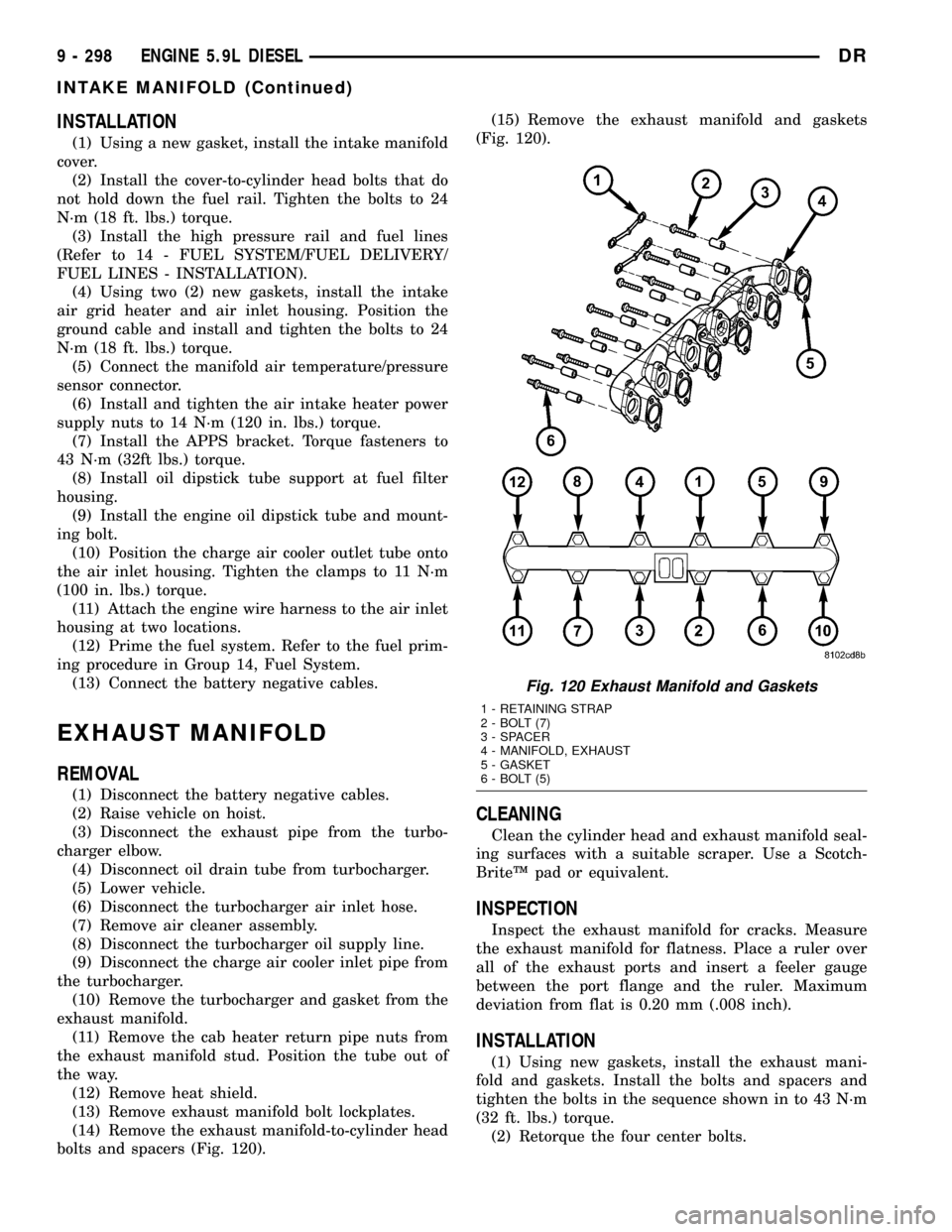
bolts and spacers (Fig. 120).(15) Remove the exhaust manifold and gaskets
(Fig. 120).
CLEANING
Clean the cylinder head and exhaust manifold seal-
ing surfaces with a suitable scraper. Use a Scotch-
BriteŸ pad or equivalent.
INSPECTION
Inspect the exhaust manifold for cracks. Measure
the exhaust manifold for flatness. Place a ruler over
all of the exhaust ports and insert a feeler gauge
between the port flange and the ruler. Maximum
deviation from flat is 0.20 mm (.008 inch).
INSTALLATION
(1) Using new gaskets, install the exhaust mani-
fold and gaskets. Install the bolts and spacers and
tighten the bolts in the sequence shown in to 43 N´m
(32 ft. lbs.) torque.
(2) Retorque the four center bolts.
Fig. 120 Exhaust Manifold and Gaskets
1 - RETAINING STRAP
2 - BOLT (7)
3 - SPACER
4 - MANIFOLD, EXHAUST
5 - GASKET
6 - BOLT (5)
9 - 298 ENGINE 5.9L DIESELDR
INTAKE MANIFOLD (Continued)
Page 1541 of 2627
(2)Pre-lube the turbocharger.Pour 50 to 60 cc
(2 to 3 oz.) clean engine oil in the oil supply line fit-
ting. Carefully rotate the turbocharger impeller by
hand to distribute the oil thoroughly.
(3) Install and tighten the oil supply line to 24
N´m (18 ft. lbs.) torque.
(4) Position the charge air cooler inlet pipe to the
turbocharger. With the clamp in position, tighten the
clamp nut to 11 N´m (95 in. lbs.) torque.
(5) Position the air inlet hose to the turbocharger
(Fig. 18). Tighten the clamp to 11 N´m (95 in. lbs.)
torque.
(6) Raise vehicle on hoist.
(7) Using a new gasket, install the oil drain tube
to the turbocharger (Fig. 19). Tighten the drain tube
bolts to 24 N´m (18 ft. lbs.) torque.
(8) Tighten the oil drain tube clamps to 8 N´m (71
in. lbs.).
(9) Connect the exhaust pipe to the turbocharger
and tighten the bolts to 11.3 N´m (100 in. lbs.)
torque.
(10) Lower the vehicle.
(11) Connect the battery negative cables.
(12) Start the engine to check for leaks.
CHARGE AIR COOLER AND
PLUMBING
DESCRIPTION
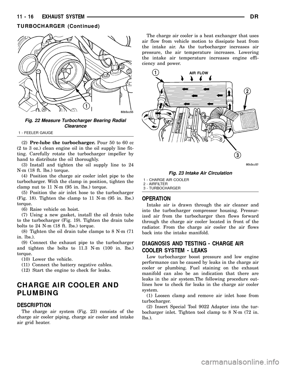
The charge air system (Fig. 23) consists of the
charge air cooler piping, charge air cooler and intake
air grid heater.The charge air cooler is a heat exchanger that uses
air flow from vehicle motion to dissipate heat from
the intake air. As the turbocharger increases air
pressure, the air temperature increases. Lowering
the intake air temperature increases engine effi-
ciency and power.
OPERATION
Intake air is drawn through the air cleaner and
into the turbocharger compressor housing. Pressur-
ized air from the turbocharger then flows forward
through the charge air cooler located in front of the
radiator. From the charge air cooler the air flows
back into the intake manifold.
DIAGNOSIS AND TESTING - CHARGE AIR
COOLER SYSTEM - LEAKS
Low turbocharger boost pressure and low engine
performance can be caused by leaks in the charge air
cooler or plumbing. Fuel staining on the exhaust
manifold can also be an indication that there are
leaks in the air system.The following procedure out-
lines how to check for leaks in the charge air cooler
system.
(1) Loosen clamp and remove air inlet hose from
turbocharger.
(2) Insert Special Tool 9022 Adapter into the tur-
bocharger inlet. Tighten tool clamp to 8 N´m (72 in.
lbs.).
Fig. 22 Measure Turbocharger Bearing Radial
Clearance
1 - FEELER GAUGE
Fig. 23 Intake Air Circulation
1 - CHARGE AIR COOLER
2 - AIRFILTER
3 - TURBOCHARGER
11 - 16 EXHAUST SYSTEMDR
TURBOCHARGER (Continued)
Page 1570 of 2627
FUEL SYSTEM
TABLE OF CONTENTS
page page
FUEL DELIVERY - GAS....................1
FUEL INJECTION - GAS...................21FUEL DELIVERY - DIESEL.................44
FUEL INJECTION - DIESEL................68
FUEL DELIVERY - GAS
TABLE OF CONTENTS
page page
FUEL DELIVERY - GAS
DESCRIPTION..........................1
OPERATION............................2
STANDARD PROCEDURE - FUEL SYSTEM
PRESSURE RELEASE...................2
SPECIFICATIONS
FUEL SYSTEM PRESSURE..............3
TORQUE - FUEL SYSTEM - EXCEPT
DIESEL..............................3
SPECIAL TOOLS
FUEL SYSTEM........................5
FUEL FILTER/PRESSURE REGULATOR
DESCRIPTION..........................5
OPERATION............................6
FUEL LEVEL SENDING UNIT / SENSOR
DESCRIPTION..........................6
OPERATION............................6
REMOVAL.............................7
INSTALLATION..........................7
FUEL LINES
DESCRIPTION..........................7
QUICK CONNECT FITTING
DESCRIPTION..........................8STANDARD PROCEDURE - QUICK-CONNECT
FITTINGS............................8
FUEL PUMP
DESCRIPTION.........................11
OPERATION...........................11
FUEL PUMP MODULE
DESCRIPTION.........................11
OPERATION...........................11
REMOVAL.............................12
INSTALLATION.........................12
FUEL RAIL
DESCRIPTION.........................12
OPERATION...........................12
REMOVAL.............................13
INSTALLATION.........................15
FUEL TANK
DESCRIPTION.........................17
OPERATION...........................17
REMOVAL- EXCEPT DIESEL..............17
INSTALLATION - EXCEPT DIESEL..........19
INLET FILTER
REMOVAL.............................20
INSTALLATION.........................20
FUEL DELIVERY - GAS
DESCRIPTION
The fuel delivery system consists of:
²a fuel pump module containing the electric fuel
pump, fuel filter/fuel pressure regulator, fuel gauge
sending unit (fuel level sensor) and a secondary fuel
filter located at the bottom of the pump module
²fuel tubes/lines/hoses
²a combination fuel filter/fuel pressure regulator
²quick-connect fittings²fuel injector rail
²fuel tank
²fuel tank filler/vent tube assembly
²fuel tank filler tube cap
²accelerator pedal
²throttle cable
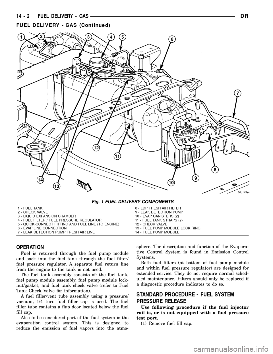
Certain fuel delivery components can be found in
(Fig. 1).
DRFUEL SYSTEM 14 - 1
Page 1571 of 2627
OPERATION
Fuel is returned through the fuel pump module
and back into the fuel tank through the fuel filter/
fuel pressure regulator. A separate fuel return line
from the engine to the tank is not used.
The fuel tank assembly consists of: the fuel tank,
fuel pump module assembly, fuel pump module lock-
nut/gasket, and fuel tank check valve (refer to Fuel
Tank Check Valve for information).
A fuel filler/vent tube assembly using a pressure/
vacuum, 1/4 turn fuel filler cap is used. The fuel
filler tube contains a flap door located below the fuel
fill cap.
Also to be considered part of the fuel system is the
evaporation control system. This is designed to
reduce the emission of fuel vapors into the atmo-sphere. The description and function of the Evapora-
tive Control System is found in Emission Control
Systems.
Both fuel filters (at bottom of fuel pump module
and within fuel pressure regulator) are designed for
extended service. They do not require normal sched-
uled maintenance. Filters should only be replaced if
a diagnostic procedure indicates to do so.
STANDARD PROCEDURE - FUEL SYSTEM
PRESSURE RELEASE
Use following procedure if the fuel injector
rail is, or is not equipped with a fuel pressure
test port.
(1) Remove fuel fill cap.
Fig. 1 FUEL DELIVERY COMPONENTS
1 - FUEL TANK 8 - LDP FRESH AIR FILTER
2 - CHECK VALVE 9 - LEAK DETECTION PUMP
3 - LIQUID EXPANSION CHAMBER 10 - EVAP CANISTERS (2)
4 - FUEL FILTER / FUEL PRESSURE REGULATOR 11 - FUEL TANK STRAPS (2)
5 - QUICK-CONNECT FITTING AND FUEL LINE (TO ENGINE) 12 - CHECK VALVE
6 - EVAP LINE CONNECTION 13 - FUEL PUMP MODULE LOCK RING
7 - LEAK DETECTION PUMP FRESH AIR LINE 14 - FUEL PUMP MODULE
14 - 2 FUEL DELIVERY - GASDR
FUEL DELIVERY - GAS (Continued)