1998 DODGE RAM 1500 Engine cranks no start
[x] Cancel search: Engine cranks no startPage 548 of 2627

tioned at the relative engine speed position on the
gauge scale until the engine stops running, or until
the ignition switch is turned to the Off position,
whichever occurs first.
²Communication Error- If the cluster fails to
receive an engine speed message, it will hold the
gauge needle at the last indication for about three
seconds, or until the ignition switch is turned to the
Off position, whichever occurs first. After three sec-
onds, the gauge needle will return to the left end of
the gauge scale.
²Actuator Test- Each time the cluster is put
through the actuator test, the tachometer needle will
be swept to several calibration points on the gauge
scale in a prescribed sequence in order to confirm the
functionality of the gauge and the cluster control cir-
cuitry.
On vehicles with a gasoline engine, the PCM con-
tinually monitors the crankshaft position sensor to
determine the engine speed. On vehicles with a die-
sel engine, the ECM continually monitors the engine
speed sensor to determine the engine speed. The
PCM or ECM then sends the proper engine speed
messages to the instrument cluster. For further diag-
nosis of the tachometer or the instrument cluster cir-
cuitry that controls the gauge, (Refer to 8 -
ELECTRICAL/INSTRUMENT CLUSTER - DIAGNO-
SIS AND TESTING). For proper diagnosis of the
crankshaft position sensor, the engine speed sensor,
the PCM, the ECM, the PCI data bus, or the elec-
tronic message inputs to the instrument cluster that
control the tachometer, a DRBIIItscan tool is
required. Refer to the appropriate diagnostic infor-
mation.
TOW/HAUL INDICATOR
DESCRIPTION
A tow/haul indicator is standard equipment on all
instrument clusters (Fig. 30). However, on vehicles
not equipped with the optional overdrive automatic
transmission, this indicator is electronically disabled.
The tow/haul indicator consists of the text ªTOW/
HAULº, which appears in the lower portion of the
odometer/trip odometer indicator Vacuum Fluores-
cent Display (VFD) unit. The VFD is soldered onto
the cluster electronic circuit board and is visible
through a window with a smoked clear lens located
on the lower edge of the tachometer gauge dial face
of the cluster overlay. The dark lens over the VFDprevents the indicator from being clearly visible
when it is not illuminated. The text ªTOW/HAULº
appear in an amber color and at the same lighting
level as the odometer/trip odometer information
when they are illuminated by the instrument cluster
electronic circuit board. The tow/haul indicator is ser-
viced as a unit with the VFD in the instrument clus-
ter.
OPERATION
The tow/haul indicator gives an indication to the
vehicle operator when the Off position of the tow/
haul switch has been selected, disabling the electron-
ically controlled overdrive feature of the automatic
transmission. This indicator is controlled by the
instrument cluster circuit board based upon cluster
programming and electronic messages received by
the cluster from the Powertrain Control Module
(PCM) over the Programmable Communications
Interface (PCI) data bus. The tow/haul indicator is
completely controlled by the instrument cluster logic
circuit, and that logic will only allow this indicator to
operate when the instrument cluster receives a bat-
tery current input on the fused ignition switch out-
put (run-start) circuit. Therefore, the indicator will
always be off when the ignition switch is in any posi-
tion except On or Start. The indicator only illumi-
nates when it is switched to ground by the
instrument cluster circuitry. The instrument cluster
will turn on the tow/haul off indicator for the follow-
ing reasons:
²Tow/Haul Lamp-On Message- Each time the
cluster receives a tow/haul lamp-on message from the
PCM indicating that the Off position of the tow/haul
switch has been selected, the tow/haul indicator will
be illuminated. The indicator remains illuminated
until the cluster receives a tow/haul lamp-off mes-
sage from the PCM, or until the ignition switch is
turned to the Off position, whichever occurs first.
²Actuator Test- Each time the cluster is put
through the actuator test, the tow/haul indicator will
be turned on, then off again during the VFD portion
of the test to confirm the functionality of the VFD
and the cluster control circuitry.
The PCM continually monitors the tow/haul switch
to determine the proper outputs to the automatic
transmission. The PCM then sends the proper tow/
haul lamp-on and lamp-off messages to the instru-
ment cluster. For further diagnosis of the tow/haul
indicator or the instrument cluster circuitry that con-
trols the indicator, (Refer to 8 - ELECTRICAL/IN-
STRUMENT CLUSTER - DIAGNOSIS AND
TESTING). For proper diagnosis of the overdrive con-
trol system, the PCM, the PCI data bus, or the elec-
tronic message inputs to the instrument cluster that
control the tow/haul indicator, a DRBIIItscan tool is
Fig. 30 Tow/Haul Indicator
DRINSTRUMENT CLUSTER 8J - 39
TACHOMETER (Continued)
Page 832 of 2627

8W-30 FUEL/IGNITION SYSTEM
Component Page
A/C Compressor Clutch Relay............ 8W-30-9, 58
A/C Pressure Transducer......... 8W-30-23, 28, 29, 45
Accelerator Pedal Position Sensor . . . 8W-30-29, 47, 64, 65
Adjustable Pedal Motor................. 8W-30-61
Adjustable Pedal Relay.................. 8W-30-61
Adjustable Pedal Switch................. 8W-30-61
Ambient Temperature Sensor............. 8W-30-30
Auto Shut Down Relay................... 8W-30-4
Battery............................ 8W-30-52
Battery Temperature Sensor............ 8W-30-12, 56
Brake Lamp Switch............. 8W-30-8, 36, 57, 63
Camshaft Position Sensor........ 8W-30-10, 29, 45, 46
Capacitor........................... 8W-30-13
Clockspring..................... 8W-30-8, 36, 59
Coil On Plug No. 1.................. 8W-30-14, 39
Coil On Plug No. 2.................. 8W-30-15, 37
Coil On Plug No. 3.................. 8W-30-14, 39
Coil On Plug No. 4.................. 8W-30-15, 37
Coil On Plug No. 5.................. 8W-30-16, 39
Coil On Plug No. 6.................. 8W-30-13, 37
Coil On Plug No. 7.................. 8W-30-16, 39
Coil On Plug No. 8.................. 8W-30-13, 37
Condenser Fan Relay.................... 8W-30-9
Controller Antilock Brake............ 8W-30-6, 11, 57
Crankshaft Position Sensor............ 8W-30-10, 46
Data Link Connector............... 8W-30-9, 22, 55
Data Link Connector-Engine.............. 8W-30-51
EGR Solenoid................... 8W-30-28, 29, 32
Electronic Throttle Control Module.......... 8W-30-35
Engine Control Module....... 8W-30-42, 43, 44, 45, 46,
47, 48, 49, 50, 51, 52, 53, 54,
55, 56, 57, 58, 59, 60, 62, 63, 64, 65
Engine Coolant Temperature Sensor.... 8W-30-23, 41, 47
Engine Oil Pressure Switch.......... 8W-30-2, 53, 56
EVAP/Purge Solenoid................... 8W-30-12
Front Control Module................... 8W-30-61
Fuel Control Actuator................... 8W-30-50
Fuel Heater......................... 8W-30-60
Fuel Heater Relay..................... 8W-30-60
Fuel Injector No. 1.................. 8W-30-14, 40
Fuel Injector No. 2.................. 8W-30-15, 38
Fuel Injector No. 3.................. 8W-30-14, 40
Fuel Injector No. 4.................. 8W-30-15, 38
Fuel Injector No. 5.................. 8W-30-14, 40
Fuel Injector No. 6.................. 8W-30-15, 38
Fuel Injector No. 7.................. 8W-30-16, 40
Fuel Injector No. 8.................. 8W-30-13, 38
Fuel Injector Pack No. 1................. 8W-30-42
Fuel Injector Pack No. 2............ 8W-30-42, 43, 44
Fuel Injector Pack No. 3................. 8W-30-44
Fuel Pump Module................... 8W-30-3, 58
Fuel Pump Motor...................... 8W-30-48
Fuel Pump Relay....................... 8W-30-3
Fuse 2.............................. 8W-30-4
Fuse 5........................... 8W-30-25, 62
Fuse 12............................ 8W-30-60
Fuse 17............................. 8W-30-3
Fuse 19............................ 8W-30-52
Fuse 23............................. 8W-30-2Component Page
Fuse 36.......................... 8W-30-54, 61
Fuse 40............................ 8W-30-61
Fuse 49............................. 8W-30-4
Fuse 50..................... 8W-30-2, 55, 58, 62
Fusible Link......................... 8W-30-52
G104........................ 8W-30-3, 8, 25, 60
G105............................ 8W-30-56, 58
G107........... 8W-30-2, 7, 15, 18, 19, 20, 21, 30, 32
G114 .............................. 8W-30-53
G120............................ 8W-30-51, 60
G201............................... 8W-30-6
G202.............................. 8W-30-61
Generator......................... 8W-30-7, 51
Idle Air Control Motor................... 8W-30-9
Ignition Switch..................... 8W-30-6, 22
Inlet Air Temperature Sensor............. 8W-30-49
Input Speed Sensor.................... 8W-30-24
Instrument Cluster.................... 8W-30-30
Intake Air Heater Relay No. 1............. 8W-30-56
Intake Air Heater Relay No. 2............. 8W-30-56
Intake Air Temperature Sensor.......... 8W-30-23, 41
Intake Air Temperature/Manifold Absolute
Pressure Sensor..................... 8W-30-50
Integrated Power Module.... 8W-30-2, 3, 4, 9, 25, 52, 54,
55, 58, 60, 61, 62, 64
Knock Sensor........................ 8W-30-31
Knock Sensor-Left..................... 8W-30-33
Knock Sensor-Right.................... 8W-30-33
Lift Pump Motor...................... 8W-30-51
Line Pressure Sensor................... 8W-30-17
Manifold Absolute Pressure Sensor..... 8W-30-23, 29, 41
Natural Vacuum Leak Detection Assembly..... 8W-30-7
Output Speed Sensor................. 8W-30-24, 62
Oxygen Sensor 1/1 Upstream........... 8W-30-20, 21
Oxygen Sensor 1/2 Downstream......... 8W-30-18, 19
Oxygen Sensor 2/1 Upstream........... 8W-30-20, 21
Oxygen Sensor 2/2 Downstream......... 8W-30-18, 19
Oxygen Sensor Downstream Relay........... 8W-30-4
Power Steering Pressure Switch............ 8W-30-7
Powertrain Control Module....... 8W-30-2, 3, 4, 5, 6, 7,
8, 9, 10, 11, 12, 13, 14, 15, 16,
17, 18, 19, 20, 21, 22, 23, 24,
25, 26, 27, 28, 29, 30, 31, 32,
33, 35, 36, 37, 38, 39, 40, 41
PTCNo.1 ....................... 8W-30-3, 9, 58
Pto Switch........................... 8W-30-6
Speed Control Servo.................. 8W-30-8, 63
Speed Control Switch-Left............. 8W-30-36, 59
Speed Control Switch-Right............ 8W-30-36, 59
Starter Motor Relay.................. 8W-30-2, 64
Throttle Position Sensor................. 8W-30-17
Tow/Haul Overdrive Switch............. 8W-30-6, 64
Transmission Control Relay............ 8W-30-25, 62
Transmission Range Sensor............... 8W-30-64
Transmission Solenoid Assembly......... 8W-30-54, 62
Transmission Solenoid/TRS Assembly . 8W-30-5, 25, 26, 27
Vacuum Pump........................ 8W-30-58
Vistronic Fan Drive.................... 8W-30-54
Water In Fuel Sensor................ 8W-30-47, 48
DR8W-30 FUEL/IGNITION SYSTEM 8W - 30 - 1
Page 1234 of 2627
(12) Disconnect heater hoses from heater core and
remove hose assembly.
(13) Disconnect throttle and speed control cables.
(14) Remove upper radiator hose from engine.
(15) Remove lower radiator hose from engine.
(16) Remove radiator/cooling module assembly.
(17) Disconnect the engine to body ground straps
at the left side of cowl.
(18) Disconnect the engine wiring harness at the
following points:
²Intake air temperature (IAT) sensor
²Fuel Injectors
²Throttle Position (TPS) Switch
²Idle Air Control (IAC) Motor
²Engine Oil Pressure Switch
²Engine Coolant Temperature (ECT) Sensor
²Manifold Absolute Pressure MAP) Sensor
²Camshaft Position (CMP) Sensor
²Coil Over Plugs
²Crankshaft Position Sensor
(19) Remove coil over plugs.
(20) Release fuel rail pressure.
(21) Remove fuel rail and secure away from
engine.
NOTE: It is not necessary to release the quick con-
nect fitting from the fuel supply line for engine
removal.
(22) Remove the PCV hose.
(23) Remove the breather hoses.
(24) Remove the vacuum hose for the power brake
booster.
(25) Disconnect knock sensors.
(26) Remove engine oil dipstick tube.
(27) Remove intake manifold.
(28) Install engine lifting fixture,special tool#8247,
using original fasteners from the removed intake
manifold, and fuel rail. Torque to factory specifica-
tions.
NOTE: Recheck bolt torque for engine lift plate
before removing engine.
(29) Secure the left and right engine wiring har-
nesses away from engine.
(30) Raise vehicle.
(31) Disconnect oxygen sensor wiring.
(32) Disconnect crankshaft postion sensor.
(33) Disconnect the engine block heater power
cable, if equipped.
(34) Disconnect the front propshaft at the front
differential and secure out of way.
NOTE: It is necessary to disconnect the front prop-
shaft for access to the starter and left side exhaust
flange.(35) Remove the starter.
(36) Remove the ground straps from the left and
right side of the block.
(37) Disconnect the right and left exhaust pipes at
the manifolds and from the crossover, and remove
from the vehicle.
NOTE: The exhaust clamps at the manifolds cannot
be reused. New clamps must be used or leaks may
occur.
(38) Remove the structural cover.
(39) Remove torque convertor bolts, and mark
location for reassembly.
(40) Remove transmission bellhousing to engine
bolts.
(41) Remove left and right engine mount thru
bolts.
(42) Lower the vehicle.
(43) Support the transmission with a suitable jack.
(44) Connect a suitable engine hoist to the engine
lift plate.
(45) Remove engine from vehicle.
INSTALLATION
(1) Position the engine in the vehicle.
(2) Install both left and right side engine mounts
onto engine.
(3) Raise the vehicle.
(4) Install the transmission bellhousing to engine
mounting bolts. Tighten the bolts to 41 N´m (30ft.
lbs.).
(5) Tighten the engine mount thru bolts.
(6) Install the torque convertor bolts.
(7) Connect the ground straps on the left and right
side of the engine.
(8) Install the starter.
(9) Connect the crankshaft position sensor.
(10) Install the engine block heater power cable, if
equipped.
CAUTION: The structural cover requires a specific
torque sequence. Failure to follow this sequence
may cause severe damage to the cover.
(11) Install the structural cover.
NOTE: New clamps must be used on exhaust man-
ifold flanges. Failure to use new clamps may result
in exhaust leaks.
(12) Install the left and right exhaust pipes.
(13) Connect the left and right oxygen sensors.
(14) Lower vehicle.
(15) Remove the engine lift plate.
(16) Connect the knock sensors.
DRENGINE - 3.7L 9 - 11
ENGINE - 3.7L (Continued)
Page 1235 of 2627
(17) Connect the engine to body ground straps at
the left side of the cowl.
(18) Install the intake manifold.
(19) Install the engine oil dipstick tube.
(20) Install the power brake booster vacuum hose.
(21) Install the breather hoses.
(22) Install the PCV hose.
(23) Install the fuel rail.
(24) Install the coil over plugs.
(25) Connect the engine wiring harness at the fol-
lowing points:
²Intake air temperature (IAT) sensor
²Fuel Injectors
²Throttle Position (TPS) Switch
²Idle Air Control (IAC) Motor
²Engine Oil Pressure Switch
²Engine Coolant Temperature (ECT) Sensor
²Manifold Absolute Pressure MAP) Sensor
²Camshaft Position (CMP) Sensor
²Coil Over Plugs
²Crankshaft Position Sensor
(26) Reinstall the radiator/cooling module assem-
bly.
(27) Connect lower radiator hose.
(28) Connect upper radiator hose.
(29) Connect throttle and speed control cables.
(30) Install the heater hose assembly.
(31) Install coolant recovery bottle.
(32) Install the power steering pump.
(33) Install the generator.
(34) Install the A/C compressor.
(35) Install the drive belt.
(36) Install the fan shroud with the viscous fan
assembly.
(37) Install the radiator core support bracket.
(38) Install the air cleaner assembly.
(39) Refill the engine cooling system.
(40) Recharge the air conditioning.
(41) Install the hood.
(42) Check and fill engine oil.
(43) Connect the battery negative cable.
(44) Start the engine and check for leaks.SPECIFICATIONS
SPECIFICATIONS - 3.7L ENGINE
GENERAL SPECIFICATIONS
DESCRIPTION SPECIFICATION
Type 90É SOHC V6 12 Valve
Number of
Cylinders4
Firing Order 1-6-5-4-3-2
Lead Cylinder No. 1 Left Bank
Compression
Ratio9.1:1
Max. Variation
Between
Cylinders25%
Metric Standard
Displacement 3.7 Liters 226 Cubic
Inches
Bore 93.0 mm 3.66 in.
Stroke 90.8 mm 3.40 in.
Horsepower 210@5200 RPM
Torque 225ft. lbs.@4200 PRM
Compression
Pressure1172-1551 kPa 170-225 psi
CYLINDER BLOCK
DESCRIPTION SPECIFICATION
Metric Standard
Bore Diameter 93.0 .0075
mm3.6619 0.0003
in.
Out of Round
(MAX)0.076 mm 0.003 in.
Taper (MAX) 0.051 mm 0.002 in.
9 - 12 ENGINE - 3.7LDR
ENGINE - 3.7L (Continued)
Page 1245 of 2627
²Excessive steam (white smoke) emitting from
exhaust
²Coolant foaming
CYLINDER-TO-CYLINDER LEAKAGE TEST
To determine if an engine cylinder head gasket is
leaking between adjacent cylinders, follow the proce-
dures in Cylinder Compression Pressure Test (Refer
to 9 - ENGINE - DIAGNOSIS AND TESTING). An
engine cylinder head gasket leaking between adja-
cent cylinders will result in approximately a 50 - 70%
reduction in compression pressure.
CYLINDER-TO-WATER JACKET LEAKAGE TEST
WARNING: USE EXTREME CAUTION WHEN THE
ENGINE IS OPERATING WITH COOLANT PRES-
SURE CAP REMOVED.
VISUAL TEST METHOD
With the engine cool, remove the coolant pressure
cap. Start the engine and allow it to warm up until
thermostat opens.
If a large combustion/compression pressure leak
exists, bubbles will be visible in the coolant.
COOLING SYSTEM TESTER METHOD
WARNING: WITH COOLING SYSTEM TESTER IN
PLACE, PRESSURE WILL BUILD UP FAST. EXCES-
SIVE PRESSURE BUILT UP, BY CONTINUOUS
ENGINE OPERATION, MUST BE RELEASED TO A
SAFE PRESSURE POINT. NEVER PERMIT PRES-
SURE TO EXCEED 138 kPa (20 psi).
Install Cooling System Tester 7700 or equivalent to
pressure cap neck. Start the engine and observe the
tester's pressure gauge. If gauge pulsates with every
power stroke of a cylinder a combustion pressure
leak is evident.
CHEMICAL TEST METHOD
Combustion leaks into the cooling system can also
be checked by using Bloc-Chek Kit C-3685-A or
equivalent. Perform test following the procedures
supplied with the tool kit.
REMOVAL
(1) Disconnect the negative cable from the battery.
(2) Raise the vehicle on a hoist.
(3) Disconnect the exhaust pipe at the left side
exhaust manifold.
(4) Drain the engine coolant(Refer to 7 - COOL-
ING - STANDARD PROCEDURE).
(5) Lower the vehicle.(6) Remove the intake manifold(Refer to 9 -
ENGINE/MANIFOLDS/INTAKE MANIFOLD -
REMOVAL).
(7) Remove the master cylinder and booster assem-
bly(Refer to 5 - BRAKES/HYDRAULIC/MECHANI-
CAL/POWER BRAKE BOOSTER - REMOVAL).
(8) Remove the cylinder head cover(Refer to 9 -
ENGINE/CYLINDER HEAD/CYLINDER HEAD
COVER(S) - REMOVAL).
(9) Remove the fan shroud and fan blade assem-
bly(Refer to 7 - COOLING/ENGINE/RADIATOR FAN
- REMOVAL).
(10) Remove accessory drive belt(Refer to 7 -
COOLING/ACCESSORY DRIVE/DRIVE BELTS -
REMOVAL).
(11) Remove the power steering pump and set
aside.
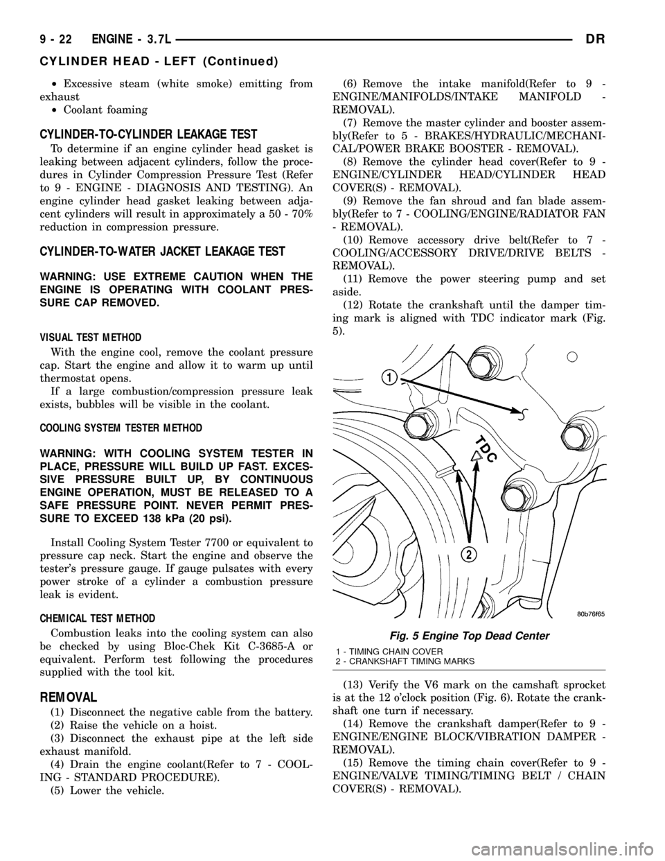
(12) Rotate the crankshaft until the damper tim-
ing mark is aligned with TDC indicator mark (Fig.
5).
(13) Verify the V6 mark on the camshaft sprocket
is at the 12 o'clock position (Fig. 6). Rotate the crank-
shaft one turn if necessary.
(14) Remove the crankshaft damper(Refer to 9 -
ENGINE/ENGINE BLOCK/VIBRATION DAMPER -
REMOVAL).
(15) Remove the timing chain cover(Refer to 9 -
ENGINE/VALVE TIMING/TIMING BELT / CHAIN
COVER(S) - REMOVAL).
Fig. 5 Engine Top Dead Center
1 - TIMING CHAIN COVER
2 - CRANKSHAFT TIMING MARKS
9 - 22 ENGINE - 3.7LDR
CYLINDER HEAD - LEFT (Continued)
Page 1248 of 2627
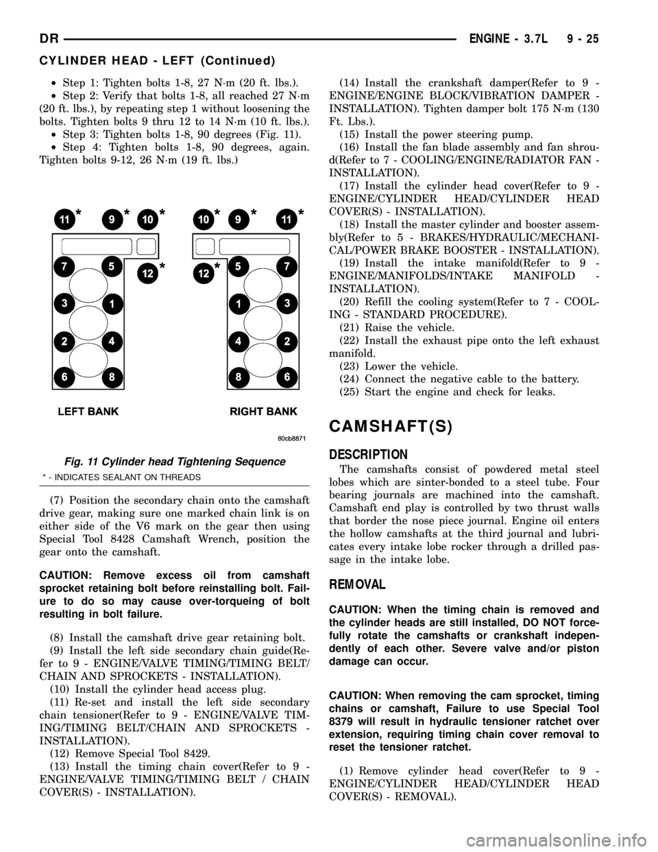
²Step 1: Tighten bolts 1-8, 27 N´m (20 ft. lbs.).
²Step 2: Verify that bolts 1-8, all reached 27 N´m
(20 ft. lbs.), by repeating step 1 without loosening the
bolts. Tighten bolts 9 thru 12 to 14 N´m (10 ft. lbs.).
²Step 3: Tighten bolts 1-8, 90 degrees (Fig. 11).
²Step 4: Tighten bolts 1-8, 90 degrees, again.
Tighten bolts 9-12, 26 N´m (19 ft. lbs.)
(7) Position the secondary chain onto the camshaft
drive gear, making sure one marked chain link is on
either side of the V6 mark on the gear then using
Special Tool 8428 Camshaft Wrench, position the
gear onto the camshaft.
CAUTION: Remove excess oil from camshaft
sprocket retaining bolt before reinstalling bolt. Fail-
ure to do so may cause over-torqueing of bolt
resulting in bolt failure.
(8) Install the camshaft drive gear retaining bolt.
(9) Install the left side secondary chain guide(Re-
fer to 9 - ENGINE/VALVE TIMING/TIMING BELT/
CHAIN AND SPROCKETS - INSTALLATION).
(10) Install the cylinder head access plug.
(11) Re-set and install the left side secondary
chain tensioner(Refer to 9 - ENGINE/VALVE TIM-
ING/TIMING BELT/CHAIN AND SPROCKETS -
INSTALLATION).
(12) Remove Special Tool 8429.
(13) Install the timing chain cover(Refer to 9 -
ENGINE/VALVE TIMING/TIMING BELT / CHAIN
COVER(S) - INSTALLATION).(14) Install the crankshaft damper(Refer to 9 -
ENGINE/ENGINE BLOCK/VIBRATION DAMPER -
INSTALLATION). Tighten damper bolt 175 N´m (130
Ft. Lbs.).
(15) Install the power steering pump.
(16) Install the fan blade assembly and fan shrou-
d(Refer to 7 - COOLING/ENGINE/RADIATOR FAN -
INSTALLATION).
(17) Install the cylinder head cover(Refer to 9 -
ENGINE/CYLINDER HEAD/CYLINDER HEAD
COVER(S) - INSTALLATION).
(18) Install the master cylinder and booster assem-
bly(Refer to 5 - BRAKES/HYDRAULIC/MECHANI-
CAL/POWER BRAKE BOOSTER - INSTALLATION).
(19) Install the intake manifold(Refer to 9 -
ENGINE/MANIFOLDS/INTAKE MANIFOLD -
INSTALLATION).
(20) Refill the cooling system(Refer to 7 - COOL-
ING - STANDARD PROCEDURE).
(21) Raise the vehicle.
(22) Install the exhaust pipe onto the left exhaust
manifold.
(23) Lower the vehicle.
(24) Connect the negative cable to the battery.
(25) Start the engine and check for leaks.
CAMSHAFT(S)
DESCRIPTION
The camshafts consist of powdered metal steel
lobes which are sinter-bonded to a steel tube. Four
bearing journals are machined into the camshaft.
Camshaft end play is controlled by two thrust walls
that border the nose piece journal. Engine oil enters
the hollow camshafts at the third journal and lubri-
cates every intake lobe rocker through a drilled pas-
sage in the intake lobe.
REMOVAL
CAUTION: When the timing chain is removed and
the cylinder heads are still installed, DO NOT force-
fully rotate the camshafts or crankshaft indepen-
dently of each other. Severe valve and/or piston
damage can occur.
CAUTION: When removing the cam sprocket, timing
chains or camshaft, Failure to use Special Tool
8379 will result in hydraulic tensioner ratchet over
extension, requiring timing chain cover removal to
reset the tensioner ratchet.
(1) Remove cylinder head cover(Refer to 9 -
ENGINE/CYLINDER HEAD/CYLINDER HEAD
COVER(S) - REMOVAL).
Fig. 11 Cylinder head Tightening Sequence
* - INDICATES SEALANT ON THREADS
DRENGINE - 3.7L 9 - 25
CYLINDER HEAD - LEFT (Continued)
Page 1254 of 2627
ROCKER ARM
DESCRIPTION
The rocker arms are steel stampings with an inte-
gral roller bearing. The rocker arms incorporate a 2.8
mm (0.11 inch) oil hole in the lash adjuster socket for
roller and camshaft lubrication.
REMOVAL
NOTE: Disconnect the battery negative cable to pre-
vent accidental starter engagement.
(1) Remove the cylinder head cover (Refer to 9 -
ENGINE/CYLINDER HEAD/CYLINDER HEAD
COVER(S) - REMOVAL).
(2) For rocker arm removal on cylinder No. 4,
Rotate the crankshaft until cylinder No. 1 is at BDC
intake stroke.
(3) For rocker arm removal on cylinder No. 1,
Rotate the crankshaft until cylinder No. 1 is at BDC
combustion stroke.
(4) For rocker arm removal on cylinders No. 3 and
No. 5, Rotate the crankshaft until cylinder No. 1 is at
TDC exhaust stroke.
(5) For rocker arm removal on cylinders No. 2 and
No. 6, Rotate the crankshaft until cylinder No. 1 is at
TDC ignition stroke.
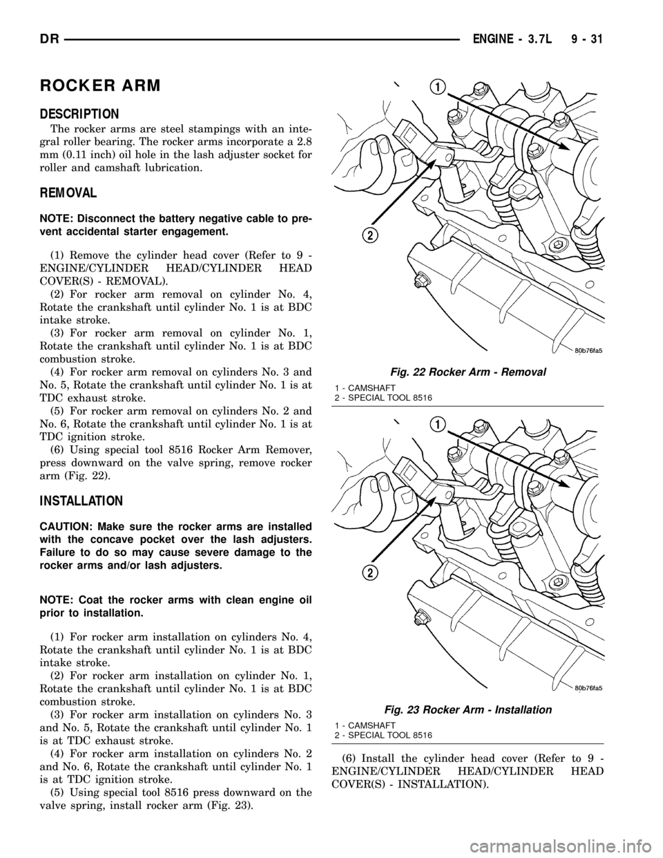
(6) Using special tool 8516 Rocker Arm Remover,
press downward on the valve spring, remove rocker
arm (Fig. 22).
INSTALLATION
CAUTION: Make sure the rocker arms are installed
with the concave pocket over the lash adjusters.
Failure to do so may cause severe damage to the
rocker arms and/or lash adjusters.
NOTE: Coat the rocker arms with clean engine oil
prior to installation.
(1) For rocker arm installation on cylinders No. 4,
Rotate the crankshaft until cylinder No. 1 is at BDC
intake stroke.
(2) For rocker arm installation on cylinder No. 1,
Rotate the crankshaft until cylinder No. 1 is at BDC
combustion stroke.
(3) For rocker arm installation on cylinders No. 3
and No. 5, Rotate the crankshaft until cylinder No. 1
is at TDC exhaust stroke.
(4) For rocker arm installation on cylinders No. 2
and No. 6, Rotate the crankshaft until cylinder No. 1
is at TDC ignition stroke.
(5) Using special tool 8516 press downward on the
valve spring, install rocker arm (Fig. 23).(6) Install the cylinder head cover (Refer to 9 -
ENGINE/CYLINDER HEAD/CYLINDER HEAD
COVER(S) - INSTALLATION).
Fig. 22 Rocker Arm - Removal
1 - CAMSHAFT
2 - SPECIAL TOOL 8516
Fig. 23 Rocker Arm - Installation
1 - CAMSHAFT
2 - SPECIAL TOOL 8516
DRENGINE - 3.7L 9 - 31
Page 1256 of 2627
(6) Air ingested into oil due to broken or cracked
oil pump pick up.
(7) Worn valve guides.
(8) Rocker arm ears contacting valve spring
retainer.
(9) Rocker arm loose, adjuster stuck or at maxi-
mum extension and still leaves lash in the system.
(10) Oil leak or excessive cam bore wear in cylin-
der head.
(11) Faulty lash adjuster.
a. Check lash adjusters for sponginess while
installed in cylinder head and cam on camshaft at
base circle. Depress part of rocker arm over adjuster.
Normal adjusters should feel very firm. Spongy
adjusters can be bottomed out easily.
b. Remove suspected lash adjusters, and replace.
c. Before installation, make sure adjusters are at
least partially full of oil. This can be verified by little
or no plunger travel when lash adjuster is depressed.
REMOVAL
(1) Disconnect battery negative cable.
(2) Raise the vehicle on a hoist.
(3) Disconnect the exhaust pipe at the right side
exhaust manifold.
(4) Drain the engine coolant(Refer to 7 - COOL-
ING - STANDARD PROCEDURE).
(5) Lower the vehicle.
(6) Remove the intake manifold(Refer to 9 -
ENGINE/MANIFOLDS/INTAKE MANIFOLD -
REMOVAL).
(7) Remove the cylinder head cover(Refer to 9 -
ENGINE/CYLINDER HEAD - REMOVAL).
(8) Remove the fan shroud(Refer to 7 - COOLING/
ENGINE/RADIATOR FAN - REMOVAL).
(9) Remove oil fill housing from cylinder head.
(10) Remove accessory drive belt(Refer to 7 -
COOLING/ACCESSORY DRIVE/DRIVE BELTS -
REMOVAL).
(11) Rotate the crankshaft until the damper timing
mark is aligned with TDC indicator mark.
(12) Verify the V6 mark on the camshaft sprocket
is at the 12 o'clock position. Rotate the crankshaft
one turn if necessary.
(13) Remove the crankshaft damper(Refer to 9 -
ENGINE/ENGINE BLOCK/VIBRATION DAMPER -
REMOVAL).
(14) Remove the timing chain cover(Refer to 9 -
ENGINE/VALVE TIMING/TIMING BELT / CHAIN
COVER(S) - REMOVAL).
(15) Lock the secondary timing chains to the idler
sprocket using Special Tool 8429 Timing Chain Hold-
ing Fixture.NOTE: Mark the secondary timing chain prior to
removal to aid in installation.
(16) Mark the secondary timing chain, one link on
each side of the V6 mark on the camshaft drive gear.
(17) Remove the right side secondary chain ten-
sioner(Refer to 9 - ENGINE/VALVE TIMING/TIM-
ING BELT/CHAIN AND SPROCKETS - REMOVAL).
(18) Remove the cylinder head access plug.
(19) Remove the right side secondary chain
guide(Refer to 9 - ENGINE/VALVE TIMING/TIMING
BELT/CHAIN AND SPROCKETS - REMOVAL).
CAUTION: The nut on the right side camshaft
sprocket should not be removed for any reason, as
the sprocket and camshaft sensor target wheel is
serviced as an assembly. If the nut was removed,
torque nut to 5 N´m (44 in. lbs.).
(20) Remove the retaining bolt and the camshaft
drive gear.
CAUTION: Do not allow the engine to rotate. severe
damage to the valve train can occur.
CAUTION: Do not overlook the four smaller bolts at
the front of the cylinder head. Do not attempt to
remove the cylinder head without removing these
four bolts.
CAUTION: Do not hold or pry on the camshaft tar-
get wheel for any reason. A damaged target wheel
can result in a vehicle no start condition.
NOTE: The cylinder head is attached to the cylinder
block with twelve bolts.
(21) Remove the cylinder head retaining bolts.
(22) Remove the cylinder head and gasket. Discard
the gasket.
CAUTION: Do not lay the cylinder head on its gas-
ket sealing surface, do to the design of the cylinder
head gasket any distortion to the cylinder head
sealing surface may prevent the gasket from prop-
erly sealing resulting in leaks.
DRENGINE - 3.7L 9 - 33
CYLINDER HEAD - RIGHT (Continued)