1998 DODGE RAM 1500 Drivers side
[x] Cancel search: Drivers sidePage 701 of 2627

is released before parking the wiper blades near the
base of the windshield. If the control knob is held in
the depressed Wash position for more than about
thirty seconds, washer system operation will be sus-
pended until the control knob is released for about
two seconds then cycled back to the Wash position.
OPERATION
The wiper and washer system is designed to pro-
vide the vehicle operator with a convenient, safe, and
reliable means of maintaining visibility through the
windshield glass. The various components of this sys-
tem are designed to convert electrical energy pro-
duced by the vehicle electrical system into the
mechanical action of the wiper blades to wipe the
outside surface of the glass, as well as into the
hydraulic action of the washer system to apply
washer fluid stored in an on-board reservoir to the
area of the glass to be wiped. When combined, these
components provide the means to effectively main-
tain clear visibility for the vehicle operator by remov-
ing excess accumulations of rain, snow, bugs, mud, or
other minor debris from the outside windshield glass
surface that might be encountered while driving the
vehicle under numerous types of inclement operating
conditions.
The vehicle operator initiates all wiper and washer
system functions with the control knob on the end of
the control stalk of the multi-function switch that
extends from the left side of the steering column, just
below the steering wheel. Rotating the control knob
on the end of the control stalk, selects the Off, Delay,
Low, or High wiper system operating modes. In the
Delay mode, the control knob also allows the vehicle
operator to select from one of five intermittent wipe
Delay intervals. Depressing the control knob towards
the steering column actuates the momentary washer
system switch, which selects the Wash, Wipe-After-
Wash, and Pulse Wipe Modes depending upon when
and how long the switch is held closed. The multi-
function switch provides hard wired resistor multi-
plexed inputs to the instrument cluster for all of the
wiper and washer system functions. The instrument
cluster then sends electronic messages to the Front
Control Module (FCM) over the Programmable Com-
munications Interface (PCI) data bus requesting the
appropriate wiper and washer system operating
modes.
Wiper and washer system operation are completely
controlled by the instrument cluster and FCM logic
circuits, and that logic will only allow these systems
to operate when the ignition switch is in the Acces-
sory or On positions. Battery current is directed from
a B(+) fuse in the Integrated Power Module (IPM) to
the wiper on/off relay and the wiper high/low relay in
the IPM through a fused B(+) circuit. The FCM useslow side drivers to control wiper system operation by
energizing or de-energizing the wiper high/low and
wiper on/off relays. The FCM uses a high side driver
to control the operation of the washer pump motor
unit. The multi-function switch circuitry receives a
clean ground output from the instrument cluster on a
multi-function switch return circuit, then provides
resistor multiplexed inputs to the instrument cluster
on an intermittent wipe mux circuit to indicate the
selected wiper system mode and on a wash/beam
select mux circuit to indicate the selected washer sys-
tem mode.
The hard wired circuits and components of the
wiper and washer system may be diagnosed and
tested using conventional diagnostic tools and proce-
dures. However, conventional diagnostic methods
may not prove conclusive in the diagnosis of the
instrument cluster, the FCM, or the electronic mes-
sage inputs to or outputs from the instrument cluster
or FCM that control the wiper and washer system
operating modes. The most reliable, efficient, and
accurate means to diagnose the instrument cluster or
the FCM inputs and outputs related to the various
wiper and washer system operating modes requires
the use of a DRBIIItscan tool. Refer to the appro-
priate diagnostic information.
OPERATING MODES
Following are paragraphs that briefly describe the
operation of each of the wiper and washer system
operating modes.
CONTINUOUS WIPE MODE
When the Low position of the control knob on the
control stalk of the multi-function switch is selected
the instrument cluster sends an electronic wiper
switch low message to the FCM, then the FCM ener-
gizes the wiper on/off relay. This directs battery cur-
rent through the normally open contacts of the
energized wiper on/off relay and the normally closed
contacts of the de-energized wiper high/low relay to
the low speed brush of the wiper motor, causing the
wipers to cycle at low speed.
When the High position of the control knob is
selected the instrument cluster sends an electronic
wiper switch high message to the FCM, then the
FCM energizes both the wiper on/off relay and the
wiper high/low relay. This directs battery current
through the normally open contacts of the energized
wiper on/off relay and the normally open contacts of
the energized wiper high/low relay to the high speed
brush of the wiper motor, causing the wipers to cycle
at high speed.
When the Off position of the multi-function switch
control knob is selected, the instrument cluster sends
an electronic wiper switch off message to the FCM. If
8R - 4 WIPERS/WASHERSDR
WIPERS/WASHERS (Continued)
Page 1300 of 2627
block. A large washer on the idler shaft bolt and the
rear flange of the idler shaft are used to control
sprocket thrust movement. Pressurized oil is routed
through the center of the idler shaft to provide lubri-
cation for the two bushings used in the idler sprocket
assembly.
There are two secondary drive chains, both are
roller type, one to drive the camshaft in each SOHC
cylinder head. There are no shaft speed changes in
the secondary chain drive system. Each secondary
chain drives a 26 tooth cam sprocket directly from
the 26 tooth sprocket on the idler sprocket assembly.
A fixed chain guide and a hydraulic oil damped ten-
sioner are used to maintain tension in each second-
ary chain system. The hydraulic tensioners for the
secondary chain systems are fed pressurized oil from
oil reservoir pockets in the block. Each tensioner
incorporates a controlled leak path through a device
known as a vent disc located in the nose of the piston
to manage chain loads. Each tensioner also has a
mechanical ratchet system that limits chain slack if
the tensioner piston bleeds down after engine shut
down. The tensioner arms and guides also utilize
nylon wear faces for low friction and long wear. The
secondary timing chains receive lubrication from a
small orifice in the tensioners. This orifice is pro-
tected from clogging by a fine mesh screen which is
located on the back of the hydraulic tensioners.
STANDARD PROCEDURE
MEASURING TIMING CHAIN WEAR
NOTE: This procedure must be performed with the
timing chain cover removed.
(1) Remove the timing chain cover (Refer to 9 -
ENGINE/VALVE TIMING/TIMING BELT/CHAIN
AND SPROCKETS - REMOVAL).
(2) To determine if the secondary timing chains
are worn, rotate the engine clockwise until maximum
tensioner piston extension is obtained. Measure the
distance between the secondary timing chain ten-
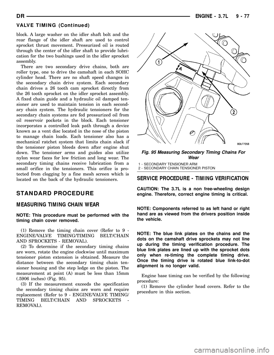
sioner housing and the step ledge on the piston. The
measurement at point (A) must be less than 15mm
(.5906 inches) (Fig. 95).
(3) If the measurement exceeds the specification
the secondary timing chains are worn and require
replacement (Refer to 9 - ENGINE/VALVE TIMING/
TIMING BELT/CHAIN AND SPROCKETS -
REMOVAL).
SERVICE PROCEDURE - TIMING VERIFICATION
CAUTION: The 3.7L is a non free-wheeling design
engine. Therefore, correct engine timing is critical.
NOTE: Components referred to as left hand or right
hand are as viewed from the drivers position inside
the vehicle.
NOTE: The blue link plates on the chains and the
dots on the camshaft drive sprockets may not line
up during the timing verification procedure. The
blue link plates are lined up with the sprocket dots
only when re-timing the complete timing drive.
Once the timing drive is rotated blue link-to-dot
alignment is no longer valid.
Engine base timing can be verified by the following
procedure:
(1) Remove the cylinder head covers. Refer to the
procedure in this section.
Fig. 95 Measuring Secondary Timing Chains For
Wear
1 - SECONDARY TENSIONER ARM
2 - SECONDARY CHAIN TENSIONER PISTON
DRENGINE - 3.7L 9 - 77
VALVE TIMING (Continued)
Page 1390 of 2627
sprocket assembly. A fixed chain guide and a hydrau-
lic oil damped tensioner are used to maintain tension
in each secondary chain system. The hydraulic ten-
sioners for the secondary chain systems are fed pres-
surized oil from oil reservoir pockets in the block.
Each tensioner also has a mechanical ratchet system
that limits chain slack if the tensioner piston bleeds
down after engine shut down. The tensioner arms
and guides also utilize nylon wear faces for low fric-
tion and long wear. The secondary timing chains
receive lubrication from a small orifice in the ten-
sioners. This orifice is protected from clogging by a
fine mesh screen which is located on the back of the
hydraulic tensioners.
STANDARD PROCEDURE
STANDARD PROCEDUREÐMEASURING
TIMING CHAIN WEAR
NOTE: This procedure must be performed with the
timing chain cover removed.
(1) Remove the timing chain cover. (Refer to 9 -
ENGINE/VALVE TIMING/TIMING BELT / CHAIN
COVER(S) - REMOVAL).
(2) To determine if the secondary timing chains
are worn, rotate the engine clockwise until maximum
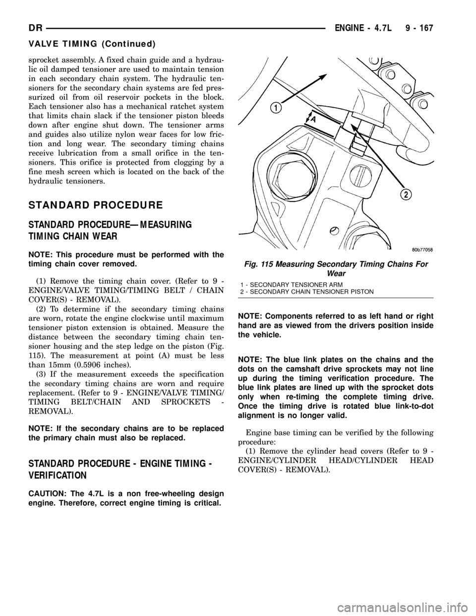
tensioner piston extension is obtained. Measure the
distance between the secondary timing chain ten-
sioner housing and the step ledge on the piston (Fig.
115). The measurement at point (A) must be less
than 15mm (0.5906 inches).
(3) If the measurement exceeds the specification
the secondary timing chains are worn and require
replacement. (Refer to 9 - ENGINE/VALVE TIMING/
TIMING BELT/CHAIN AND SPROCKETS -
REMOVAL).
NOTE: If the secondary chains are to be replaced
the primary chain must also be replaced.
STANDARD PROCEDURE - ENGINE TIMING -
VERIFICATION
CAUTION: The 4.7L is a non free-wheeling design
engine. Therefore, correct engine timing is critical.NOTE: Components referred to as left hand or right
hand are as viewed from the drivers position inside
the vehicle.
NOTE: The blue link plates on the chains and the
dots on the camshaft drive sprockets may not line
up during the timing verification procedure. The
blue link plates are lined up with the sprocket dots
only when re-timing the complete timing drive.
Once the timing drive is rotated blue link-to-dot
alignment is no longer valid.
Engine base timing can be verified by the following
procedure:
(1) Remove the cylinder head covers (Refer to 9 -
ENGINE/CYLINDER HEAD/CYLINDER HEAD
COVER(S) - REMOVAL).
Fig. 115 Measuring Secondary Timing Chains For
Wear
1 - SECONDARY TENSIONER ARM
2 - SECONDARY CHAIN TENSIONER PISTON
DRENGINE - 4.7L 9 - 167
VALVE TIMING (Continued)
Page 1440 of 2627
CAUTION: The structural cover must be held tightly
against the corner formed by the engine and the
transmission clutch housing during tightening
sequence. Failure to do so may cause damage to
the cover and engine noise.
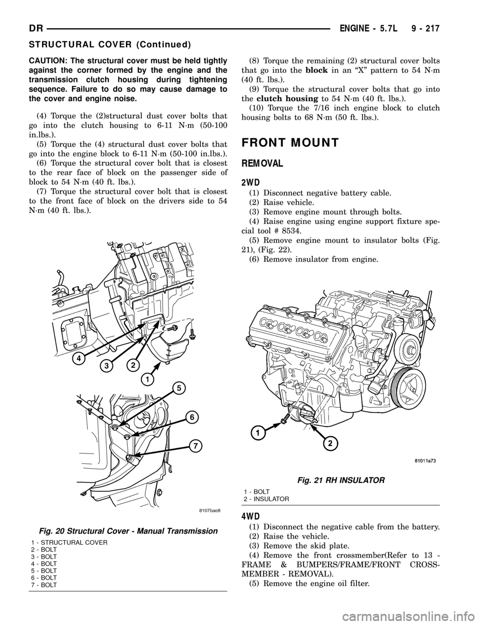
(4) Torque the (2)structural dust cover bolts that
go into the clutch housing to 6-11 N´m (50-100
in.lbs.).
(5) Torque the (4) structural dust cover bolts that
go into the engine block to 6-11 N´m (50-100 in.lbs.).
(6) Torque the structural cover bolt that is closest
to the rear face of block on the passenger side of
block to 54 N´m (40 ft. lbs.).
(7) Torque the structural cover bolt that is closest
to the front face of block on the drivers side to 54
N´m (40 ft. lbs.).(8) Torque the remaining (2) structural cover bolts
that go into theblockin an ªXº pattern to 54 N´m
(40 ft. lbs.).
(9) Torque the structural cover bolts that go into
theclutch housingto 54 N´m (40 ft. lbs.).
(10) Torque the 7/16 inch engine block to clutch
housing bolts to 68 N´m (50 ft. lbs.).
FRONT MOUNT
REMOVAL
2WD
(1) Disconnect negative battery cable.
(2) Raise vehicle.
(3) Remove engine mount through bolts.
(4) Raise engine using engine support fixture spe-
cial tool # 8534.
(5) Remove engine mount to insulator bolts (Fig.
21), (Fig. 22).
(6) Remove insulator from engine.
4WD
(1) Disconnect the negative cable from the battery.
(2) Raise the vehicle.
(3) Remove the skid plate.
(4) Remove the front crossmember(Refer to 13 -
FRAME & BUMPERS/FRAME/FRONT CROSS-
MEMBER - REMOVAL).
(5) Remove the engine oil filter.Fig. 20 Structural Cover - Manual Transmission
1 - STRUCTURAL COVER
2 - BOLT
3 - BOLT
4 - BOLT
5 - BOLT
6 - BOLT
7 - BOLT
Fig. 21 RH INSULATOR
1 - BOLT
2 - INSULATOR
DRENGINE - 5.7L 9 - 217
STRUCTURAL COVER (Continued)
Page 1581 of 2627
REMOVAL
WARNING: THE FUEL SYSTEM IS UNDER A CON-
STANT PRESSURE (EVEN WITH THE ENGINE OFF).
BEFORE SERVICING THE FUEL PUMP MODULE,
THE FUEL SYSTEM PRESSURE MUST BE
RELEASED.
(1) Drain and remove fuel tank. Refer to Fuel
Tank Removal/Installation.
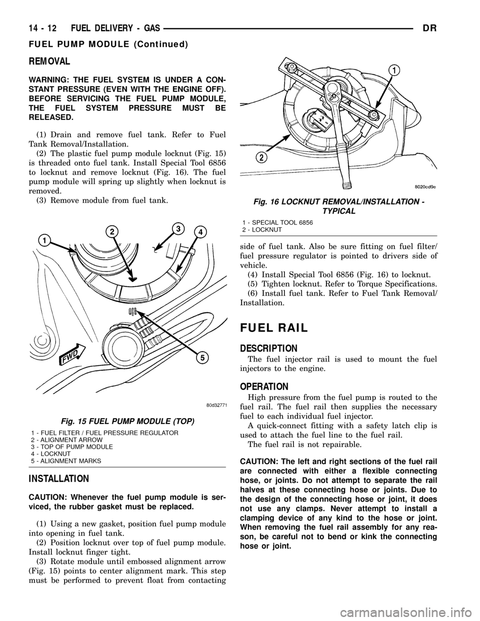
(2) The plastic fuel pump module locknut (Fig. 15)
is threaded onto fuel tank. Install Special Tool 6856
to locknut and remove locknut (Fig. 16). The fuel
pump module will spring up slightly when locknut is
removed.
(3) Remove module from fuel tank.
INSTALLATION
CAUTION: Whenever the fuel pump module is ser-
viced, the rubber gasket must be replaced.
(1) Using a new gasket, position fuel pump module
into opening in fuel tank.
(2) Position locknut over top of fuel pump module.
Install locknut finger tight.
(3) Rotate module until embossed alignment arrow
(Fig. 15) points to center alignment mark. This step
must be performed to prevent float from contactingside of fuel tank. Also be sure fitting on fuel filter/
fuel pressure regulator is pointed to drivers side of
vehicle.
(4) Install Special Tool 6856 (Fig. 16) to locknut.
(5) Tighten locknut. Refer to Torque Specifications.
(6) Install fuel tank. Refer to Fuel Tank Removal/
Installation.
FUEL RAIL
DESCRIPTION
The fuel injector rail is used to mount the fuel
injectors to the engine.
OPERATION
High pressure from the fuel pump is routed to the
fuel rail. The fuel rail then supplies the necessary
fuel to each individual fuel injector.
A quick-connect fitting with a safety latch clip is
used to attach the fuel line to the fuel rail.
The fuel rail is not repairable.
CAUTION: The left and right sections of the fuel rail
are connected with either a flexible connecting
hose, or joints. Do not attempt to separate the rail
halves at these connecting hose or joints. Due to
the design of the connecting hose or joint, it does
not use any clamps. Never attempt to install a
clamping device of any kind to the hose or joint.
When removing the fuel rail assembly for any rea-
son, be careful not to bend or kink the connecting
hose or joint.
Fig. 15 FUEL PUMP MODULE (TOP)
1 - FUEL FILTER / FUEL PRESSURE REGULATOR
2 - ALIGNMENT ARROW
3 - TOP OF PUMP MODULE
4 - LOCKNUT
5 - ALIGNMENT MARKS
Fig. 16 LOCKNUT REMOVAL/INSTALLATION -
TYPICAL
1 - SPECIAL TOOL 6856
2 - LOCKNUT
14 - 12 FUEL DELIVERY - GASDR
FUEL PUMP MODULE (Continued)
Page 1589 of 2627
INLET FILTER
REMOVAL
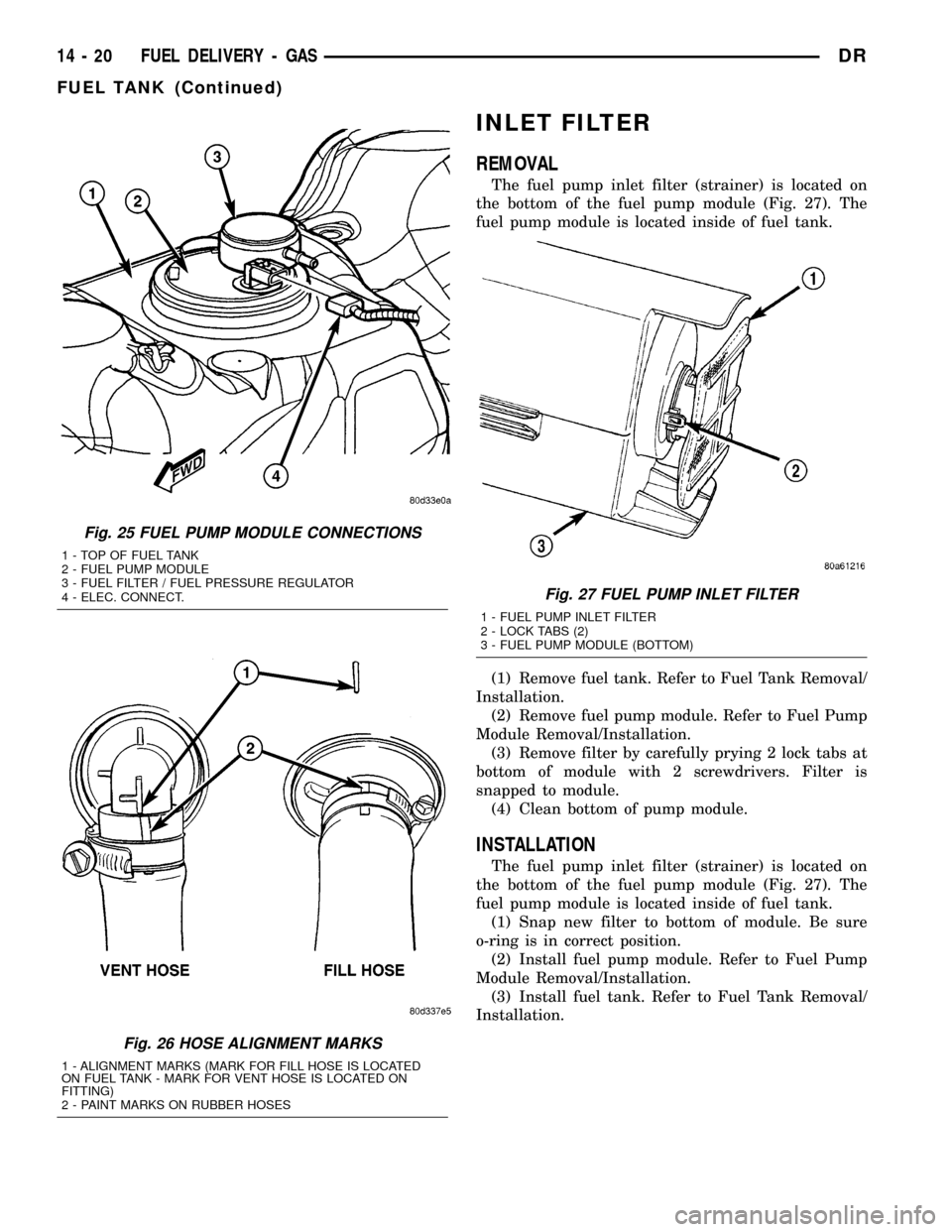
The fuel pump inlet filter (strainer) is located on
the bottom of the fuel pump module (Fig. 27). The
fuel pump module is located inside of fuel tank.
(1) Remove fuel tank. Refer to Fuel Tank Removal/
Installation.
(2) Remove fuel pump module. Refer to Fuel Pump
Module Removal/Installation.
(3) Remove filter by carefully prying 2 lock tabs at
bottom of module with 2 screwdrivers. Filter is
snapped to module.
(4) Clean bottom of pump module.
INSTALLATION
The fuel pump inlet filter (strainer) is located on
the bottom of the fuel pump module (Fig. 27). The
fuel pump module is located inside of fuel tank.
(1) Snap new filter to bottom of module. Be sure
o-ring is in correct position.
(2) Install fuel pump module. Refer to Fuel Pump
Module Removal/Installation.
(3) Install fuel tank. Refer to Fuel Tank Removal/
Installation.
Fig. 25 FUEL PUMP MODULE CONNECTIONS
1 - TOP OF FUEL TANK
2 - FUEL PUMP MODULE
3 - FUEL FILTER / FUEL PRESSURE REGULATOR
4 - ELEC. CONNECT.
Fig. 26 HOSE ALIGNMENT MARKS
1 - ALIGNMENT MARKS (MARK FOR FILL HOSE IS LOCATED
ON FUEL TANK - MARK FOR VENT HOSE IS LOCATED ON
FITTING)
2 - PAINT MARKS ON RUBBER HOSES
Fig. 27 FUEL PUMP INLET FILTER
1 - FUEL PUMP INLET FILTER
2 - LOCK TABS (2)
3 - FUEL PUMP MODULE (BOTTOM)
14 - 20 FUEL DELIVERY - GASDR
FUEL TANK (Continued)
Page 1633 of 2627
INSTALLATION
CAUTION: Whenever the fuel tank module is ser-
viced, the rubber gasket must be replaced.
(1) Thoroughly clean locknut and locknut threads
at top of tank.(2) Using new gasket, carefully position fuel tank
module into opening in fuel tank.
(3) Position locknut over top of fuel tank module.
Install locknut finger tight.
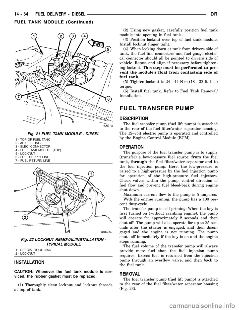
(4) When looking down at tank from drivers side of
tank, the fuel line connectors and fuel gauge electri-
cal connector should all be pointed to drivers side of
vehicle. Rotate and align if necessary before tighten-
ing locknut.This step must be performed to pre-
vent the module's float from contacting side of
fuel tank.
(5) Tighten locknut to 24 - 44 N´m (18 - 32 ft. lbs.)
torque.
(6) Install fuel tank. Refer to Fuel Tank Removal/
Installation.
FUEL TRANSFER PUMP
DESCRIPTION
The fuel transfer pump (fuel lift pump) is attached
to the rear of the fuel filter/water separator housing.
The 12±volt electric pump is operated and controlled
by the Engine Control Module (ECM).
OPERATION
The purpose of the fuel transfer pump is to supply
(transfer) a low-pressure fuel source:fromthe fuel
tank,throughthe fuel filter/water separator andto
the fuel injection pump. Here, the low-pressure is
raised to a high-pressure by the fuel injection pump
for operation of the high-pressure fuel injectors.
Check valves within the pump, control direction of
fuel flow and prevent fuel bleed-back during engine
shut down.
Maximum current flow to the pump is 5 amperes.
With the engine running, the pump has a 100 per-
cent duty-cycle.
The transfer pump is self-priming: When the key is
first turned on (without cranking engine), the pump
will operate for approximately 2 seconds and then
shut off. The pump will also operate for up to 25 sec-
onds after the starter is engaged, and then disen-
gaged and the engine is not running. The pump
shuts off immediately if the key is on and the engine
stops running.
The fuel volume of the transfer pump will always
provide more fuel than the fuel injection pump
requires. Excess fuel is returned from the injection
pump through an overflow valve, and then back to
the fuel tank.
REMOVAL
The fuel transfer pump (fuel lift pump) is attached
to the rear of the fuel filter/water separator housing
(Fig. 23).
Fig. 21 FUEL TANK MODULE - DIESEL
1 - TOP OF FUEL TANK
2 - AUX. FITTING
3 - ELEC. CONNECTOR
4 - FUEL TANK MODULE (TOP)
5 - LOCKNUT
6 - FUEL SUPPLY LINE
7 - FUEL RETURN LINE
Fig. 22 LOCKNUT REMOVAL/INSTALLATION -
TYPICAL MODULE
1 - SPECIAL TOOL 6856
2 - LOCKNUT
14 - 64 FUEL DELIVERY - DIESELDR
FUEL TANK MODULE (Continued)
Page 1638 of 2627
CAUTION: Do not attempt to remove sensor from
its mounting bracket as electronic calibration will
be destroyed (sensor-to-bracket mounting screws
are permanently attached). Two accelerator lever
set screws (Fig. 3) are used to position lever. Do
not attempt to alter positions of these set screws as
electronic calibration will be destroyed.
(1) Disconnect both negative battery cables at both
batteries.
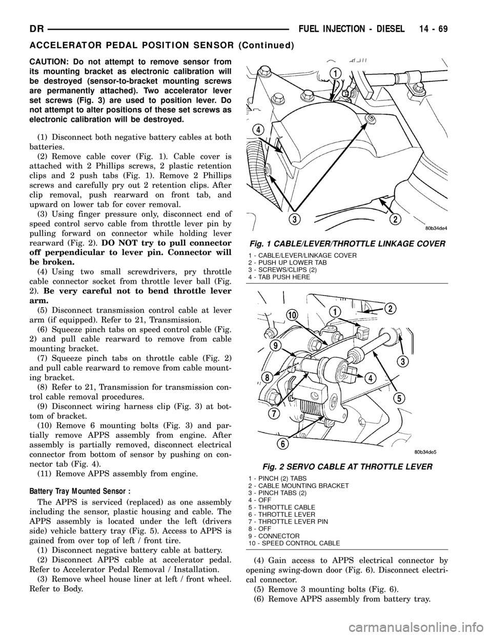
(2) Remove cable cover (Fig. 1). Cable cover is
attached with 2 Phillips screws, 2 plastic retention
clips and 2 push tabs (Fig. 1). Remove 2 Phillips
screws and carefully pry out 2 retention clips. After
clip removal, push rearward on front tab, and
upward on lower tab for cover removal.
(3) Using finger pressure only, disconnect end of
speed control servo cable from throttle lever pin by
pulling forward on connector while holding lever
rearward (Fig. 2).DO NOT try to pull connector
off perpendicular to lever pin. Connector will
be broken.
(4) Using two small screwdrivers, pry throttle
cable connector socket from throttle lever ball (Fig.
2).Be very careful not to bend throttle lever
arm.
(5) Disconnect transmission control cable at lever
arm (if equipped). Refer to 21, Transmission.
(6) Squeeze pinch tabs on speed control cable (Fig.
2) and pull cable rearward to remove from cable
mounting bracket.
(7) Squeeze pinch tabs on throttle cable (Fig. 2)
and pull cable rearward to remove from cable mount-
ing bracket.
(8) Refer to 21, Transmission for transmission con-
trol cable removal procedures.
(9) Disconnect wiring harness clip (Fig. 3) at bot-
tom of bracket.
(10) Remove 6 mounting bolts (Fig. 3) and par-
tially remove APPS assembly from engine. After
assembly is partially removed, disconnect electrical
connector from bottom of sensor by pushing on con-
nector tab (Fig. 4).
(11) Remove APPS assembly from engine.
Battery Tray Mounted Sensor :
The APPS is serviced (replaced) as one assembly
including the sensor, plastic housing and cable. The
APPS assembly is located under the left (drivers
side) vehicle battery tray (Fig. 5). Access to APPS is
gained from over top of left / front tire.
(1) Disconnect negative battery cable at battery.
(2) Disconnect APPS cable at accelerator pedal.
Refer to Accelerator Pedal Removal / Installation.
(3) Remove wheel house liner at left / front wheel.
Refer to Body.(4) Gain access to APPS electrical connector by
opening swing-down door (Fig. 6). Disconnect electri-
cal connector.
(5) Remove 3 mounting bolts (Fig. 6).
(6) Remove APPS assembly from battery tray.
Fig. 1 CABLE/LEVER/THROTTLE LINKAGE COVER
1 - CABLE/LEVER/LINKAGE COVER
2 - PUSH UP LOWER TAB
3 - SCREWS/CLIPS (2)
4 - TAB PUSH HERE
Fig. 2 SERVO CABLE AT THROTTLE LEVER
1 - PINCH (2) TABS
2 - CABLE MOUNTING BRACKET
3 - PINCH TABS (2)
4 - OFF
5 - THROTTLE CABLE
6 - THROTTLE LEVER
7 - THROTTLE LEVER PIN
8 - OFF
9 - CONNECTOR
10 - SPEED CONTROL CABLE
DRFUEL INJECTION - DIESEL 14 - 69
ACCELERATOR PEDAL POSITION SENSOR (Continued)