1998 DODGE RAM 1500 Head bolt
[x] Cancel search: Head boltPage 1583 of 2627
4.7L V-8
WARNING: THE FUEL SYSTEM IS UNDER CON-
STANT PRESSURE EVEN WITH ENGINE OFF.
BEFORE SERVICING FUEL RAIL, FUEL SYSTEM
PRESSURE MUST BE RELEASED.
CAUTION: The left and right fuel rails are replaced
as an assembly. Do not attempt to separate rail
halves at connector tubes (Fig. 19). Due to design
of tubes, it does not use any clamps. Never attempt
to install a clamping device of any kind to tubes.
When removing fuel rail assembly for any reason,
be careful not to bend or kink tubes.
(1) Remove fuel tank filler tube cap.
(2) Perform Fuel System Pressure Release Proce-
dure.
(3) Remove negative battery cable at battery.
(4) Remove air duct at throttle body air box.
(5) Remove air box at throttle body.
(6) Remove air resonator mounting bracket at
front of throttle body (2 bolts).
(7) Disconnect fuel line latch clip and fuel line at
fuel rail. A special tool will be necessary for fuel line
disconnection. Refer to Quick-Connect Fittings.
(8) Remove necessary vacuum lines at throttle
body.
(9) Disconnect electrical connectors at all 8 fuel
injectors. To remove connector refer to (Fig. 17). Push
red colored slider away from injector (1). While push-
ing slider, depress tab (2) and remove connector (3)
from injector. The factory fuel injection wiring har-
ness is numerically tagged (INJ 1, INJ 2, etc.) for
injector position identification. If harness is not
tagged, note wiring location before removal.
(10) Disconnect electrical connectors at all throttle
body sensors.
(11) Remove 8 ignition coils. Refer to Ignition Coil
Removal/Installation.
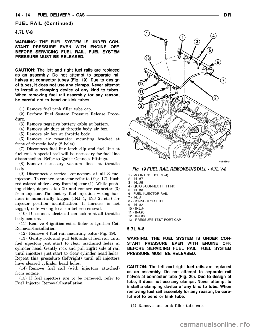
(12) Remove 4 fuel rail mounting bolts (Fig. 19).
(13) Gently rock and pullleftside of fuel rail until
fuel injectors just start to clear machined holes in
cylinder head. Gently rock and pullrightside of rail
until injectors just start to clear cylinder head holes.
Repeat this procedure (left/right) until all injectors
have cleared cylinder head holes.
(14) Remove fuel rail (with injectors attached)
from engine.
(15) If fuel injectors are to be removed, refer to
Fuel Injector Removal/Installation.
5.7L V-8
WARNING: THE FUEL SYSTEM IS UNDER CON-
STANT PRESSURE EVEN WITH ENGINE OFF.
BEFORE SERVICING FUEL RAIL, FUEL SYSTEM
PRESSURE MUST BE RELEASED.
CAUTION: The left and right fuel rails are replaced
as an assembly. Do not attempt to separate rail
halves at connector tube (Fig. 20). Due to design of
tube, it does not use any clamps. Never attempt to
install a clamping device of any kind to tube. When
removing fuel rail assembly for any reason, be care-
ful not to bend or kink tube.
(1) Remove fuel tank filler tube cap.
Fig. 19 FUEL RAIL REMOVE/INSTALL - 4.7L V-8
1 - MOUNTING BOLTS (4)
2 - INJ.#7
3 - INJ.#5
4 - QUICK-CONNECT FITTING
5 - INJ.#3
6 - FUEL INJECTOR RAIL
7 - INJ.#1
8 - CONNECTOR TUBE
9 - INJ.#2
10 - INJ.#4
11 - INJ.#6
12 - INJ.#8
13 - PRESSURE TEST PORT CAP
14 - 14 FUEL DELIVERY - GASDR
FUEL RAIL (Continued)
Page 1584 of 2627
(2) Perform Fuel System Pressure Release Proce-
dure.
(3) Remove negative battery cable at battery.
(4) Remove flex tube (air cleaner housing to
engine).
(5) Remove air resonator box at throttle body.
(6) Disconnect all spark plug cables from all spark
plugs and ignition coils. Do not remove cables from
cable routing tray. Note original cable positions while
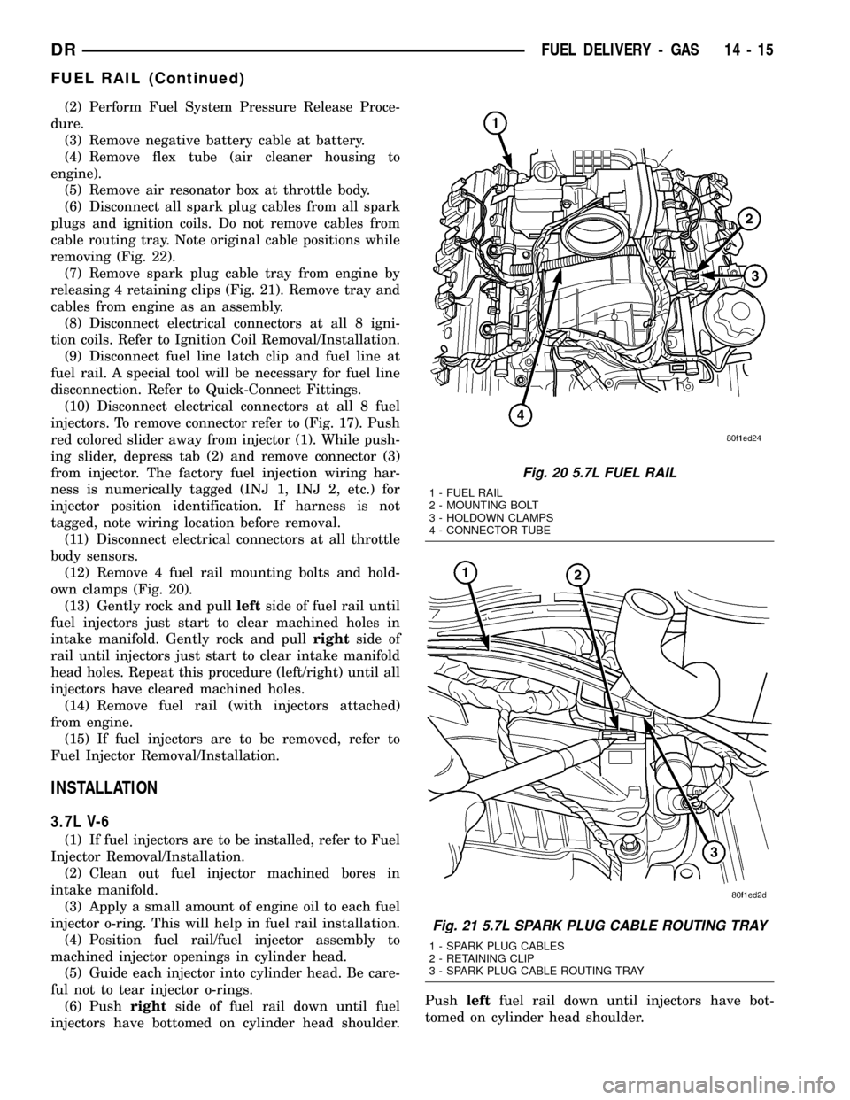
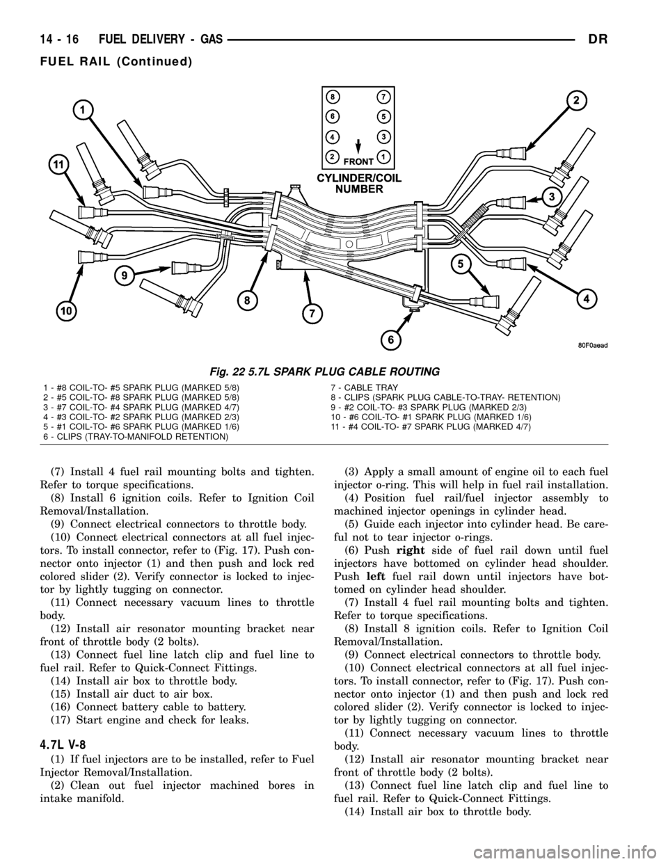
removing (Fig. 22).
(7) Remove spark plug cable tray from engine by
releasing 4 retaining clips (Fig. 21). Remove tray and
cables from engine as an assembly.
(8) Disconnect electrical connectors at all 8 igni-
tion coils. Refer to Ignition Coil Removal/Installation.
(9) Disconnect fuel line latch clip and fuel line at
fuel rail. A special tool will be necessary for fuel line
disconnection. Refer to Quick-Connect Fittings.
(10) Disconnect electrical connectors at all 8 fuel
injectors. To remove connector refer to (Fig. 17). Push
red colored slider away from injector (1). While push-
ing slider, depress tab (2) and remove connector (3)
from injector. The factory fuel injection wiring har-
ness is numerically tagged (INJ 1, INJ 2, etc.) for
injector position identification. If harness is not
tagged, note wiring location before removal.
(11) Disconnect electrical connectors at all throttle
body sensors.
(12) Remove 4 fuel rail mounting bolts and hold-
own clamps (Fig. 20).
(13) Gently rock and pullleftside of fuel rail until
fuel injectors just start to clear machined holes in
intake manifold. Gently rock and pullrightside of
rail until injectors just start to clear intake manifold
head holes. Repeat this procedure (left/right) until all
injectors have cleared machined holes.
(14) Remove fuel rail (with injectors attached)
from engine.
(15) If fuel injectors are to be removed, refer to
Fuel Injector Removal/Installation.
INSTALLATION
3.7L V-6
(1) If fuel injectors are to be installed, refer to Fuel
Injector Removal/Installation.
(2) Clean out fuel injector machined bores in
intake manifold.
(3) Apply a small amount of engine oil to each fuel
injector o-ring. This will help in fuel rail installation.
(4) Position fuel rail/fuel injector assembly to
machined injector openings in cylinder head.
(5) Guide each injector into cylinder head. Be care-
ful not to tear injector o-rings.
(6) Pushrightside of fuel rail down until fuel
injectors have bottomed on cylinder head shoulder.Pushleftfuel rail down until injectors have bot-
tomed on cylinder head shoulder.
Fig. 20 5.7L FUEL RAIL
1 - FUEL RAIL
2 - MOUNTING BOLT
3 - HOLDOWN CLAMPS
4 - CONNECTOR TUBE
Fig. 21 5.7L SPARK PLUG CABLE ROUTING TRAY
1 - SPARK PLUG CABLES
2 - RETAINING CLIP
3 - SPARK PLUG CABLE ROUTING TRAY
DRFUEL DELIVERY - GAS 14 - 15
FUEL RAIL (Continued)
Page 1585 of 2627
(7) Install 4 fuel rail mounting bolts and tighten.
Refer to torque specifications.
(8) Install 6 ignition coils. Refer to Ignition Coil
Removal/Installation.
(9) Connect electrical connectors to throttle body.
(10) Connect electrical connectors at all fuel injec-
tors. To install connector, refer to (Fig. 17). Push con-
nector onto injector (1) and then push and lock red
colored slider (2). Verify connector is locked to injec-
tor by lightly tugging on connector.
(11) Connect necessary vacuum lines to throttle
body.
(12) Install air resonator mounting bracket near
front of throttle body (2 bolts).
(13) Connect fuel line latch clip and fuel line to
fuel rail. Refer to Quick-Connect Fittings.
(14) Install air box to throttle body.
(15) Install air duct to air box.
(16) Connect battery cable to battery.
(17) Start engine and check for leaks.
4.7L V-8
(1) If fuel injectors are to be installed, refer to Fuel
Injector Removal/Installation.
(2) Clean out fuel injector machined bores in
intake manifold.(3) Apply a small amount of engine oil to each fuel
injector o-ring. This will help in fuel rail installation.
(4) Position fuel rail/fuel injector assembly to
machined injector openings in cylinder head.
(5) Guide each injector into cylinder head. Be care-
ful not to tear injector o-rings.
(6) Pushrightside of fuel rail down until fuel
injectors have bottomed on cylinder head shoulder.
Pushleftfuel rail down until injectors have bot-
tomed on cylinder head shoulder.
(7) Install 4 fuel rail mounting bolts and tighten.
Refer to torque specifications.
(8) Install 8 ignition coils. Refer to Ignition Coil
Removal/Installation.
(9) Connect electrical connectors to throttle body.
(10) Connect electrical connectors at all fuel injec-
tors. To install connector, refer to (Fig. 17). Push con-
nector onto injector (1) and then push and lock red
colored slider (2). Verify connector is locked to injec-
tor by lightly tugging on connector.
(11) Connect necessary vacuum lines to throttle
body.
(12) Install air resonator mounting bracket near
front of throttle body (2 bolts).
(13) Connect fuel line latch clip and fuel line to
fuel rail. Refer to Quick-Connect Fittings.
(14) Install air box to throttle body.
Fig. 22 5.7L SPARK PLUG CABLE ROUTING
1 - #8 COIL-TO- #5 SPARK PLUG (MARKED 5/8) 7 - CABLE TRAY
2 - #5 COIL-TO- #8 SPARK PLUG (MARKED 5/8) 8 - CLIPS (SPARK PLUG CABLE-TO-TRAY- RETENTION)
3 - #7 COIL-TO- #4 SPARK PLUG (MARKED 4/7) 9 - #2 COIL-TO- #3 SPARK PLUG (MARKED 2/3)
4 - #3 COIL-TO- #2 SPARK PLUG (MARKED 2/3) 10 - #6 COIL-TO- #1 SPARK PLUG (MARKED 1/6)
5 - #1 COIL-TO- #6 SPARK PLUG (MARKED 1/6) 11 - #4 COIL-TO- #7 SPARK PLUG (MARKED 4/7)
6 - CLIPS (TRAY-TO-MANIFOLD RETENTION)
14 - 16 FUEL DELIVERY - GASDR
FUEL RAIL (Continued)
Page 1617 of 2627
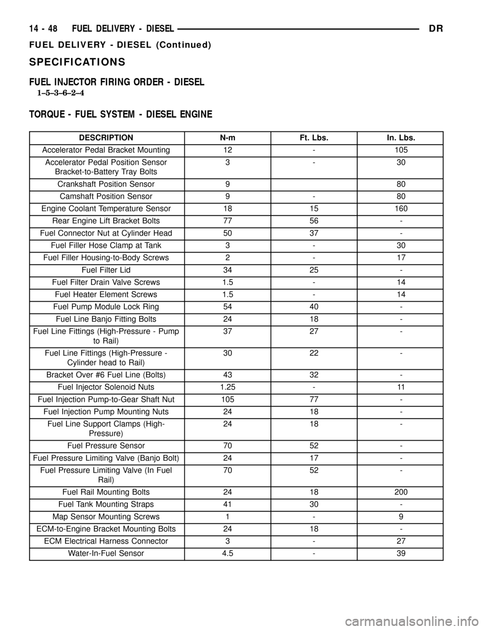
SPECIFICATIONS
FUEL INJECTOR FIRING ORDER - DIESEL
1±5±3±6±2±4
TORQUE - FUEL SYSTEM - DIESEL ENGINE
DESCRIPTION N-m Ft. Lbs. In. Lbs.
Accelerator Pedal Bracket Mounting 12 - 105
Accelerator Pedal Position Sensor
Bracket-to-Battery Tray Bolts3-30
Crankshaft Position Sensor 9 80
Camshaft Position Sensor 9 - 80
Engine Coolant Temperature Sensor 18 15 160
Rear Engine Lift Bracket Bolts 77 56 -
Fuel Connector Nut at Cylinder Head 50 37 -
Fuel Filler Hose Clamp at Tank 3 - 30
Fuel Filler Housing-to-Body Screws 2 - 17
Fuel Filter Lid 34 25 -
Fuel Filter Drain Valve Screws 1.5 - 14
Fuel Heater Element Screws 1.5 - 14
Fuel Pump Module Lock Ring 54 40 -
Fuel Line Banjo Fitting Bolts 24 18 -
Fuel Line Fittings (High-Pressure - Pump
to Rail)37 27 -
Fuel Line Fittings (High-Pressure -
Cylinder head to Rail)30 22 -
Bracket Over #6 Fuel Line (Bolts) 43 32 -
Fuel Injector Solenoid Nuts 1.25 - 11
Fuel Injection Pump-to-Gear Shaft Nut 105 77 -
Fuel Injection Pump Mounting Nuts 24 18 -
Fuel Line Support Clamps (High-
Pressure)24 18 -
Fuel Pressure Sensor 70 52 -
Fuel Pressure Limiting Valve (Banjo Bolt) 24 17 -
Fuel Pressure Limiting Valve (In Fuel
Rail)70 52 -
Fuel Rail Mounting Bolts 24 18 200
Fuel Tank Mounting Straps 41 30 -
Map Sensor Mounting Screws 1 - 9
ECM-to-Engine Bracket Mounting Bolts 24 18 -
ECM Electrical Harness Connector 3 - 27
Water-In-Fuel Sensor 4.5 - 39
14 - 48 FUEL DELIVERY - DIESELDR
FUEL DELIVERY - DIESEL (Continued)
Page 1627 of 2627
WARNING: USE EXTREME CAUTION WHEN
INSPECTING FOR HIGH-PRESSURE FUEL LEAKS.
INSPECT FOR HIGH-PRESSURE FUEL LEAKS WITH
A SHEET OF CARDBOARD. HIGH FUEL INJECTION
PRESSURE CAN CAUSE PERSONAL INJURY IF
CONTACT IS MADE WITH THE SKIN.
DIAGNOSIS AND TESTING - HIGH-PRESSURE
FUEL LINE LEAKS
High-pressure fuel line leaks can cause starting
problems and poor engine performance.
WARNING: DUE TO EXTREME FUEL PRESSURES
OF UP TO 160,000 kPa (23,206 PSI), USE EXTREME
CAUTION WHEN INSPECTING FOR HIGH-PRES-
SURE FUEL LEAKS. DO NOT GET YOUR HAND OR
A FINGER NEAR A SUSPECTED LEAK. INSPECT
FOR HIGH-PRESSURE FUEL LEAKS WITH A SHEET
OF CARDBOARD. HIGH FUEL INJECTION PRES-
SURE CAN CAUSE PERSONAL INJURY IF CON-
TACT IS MADE WITH THE SKIN.
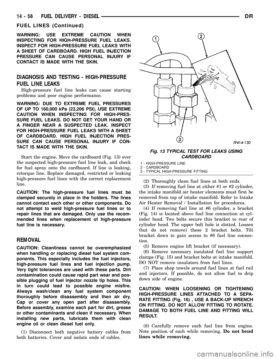
Start the engine. Move the cardboard (Fig. 13) over
the suspected high-pressure fuel line leak, and check
for fuel spray onto the cardboard. If line is leaking,
retorque line. Replace damaged, restricted or leaking
high-pressure fuel lines with the correct replacement
line.
CAUTION: The high-pressure fuel lines must be
clamped securely in place in the holders. The lines
cannot contact each other or other components. Do
not attempt to weld high-pressure fuel lines or to
repair lines that are damaged. Only use the recom-
mended lines when replacement of high-pressure
fuel line is necessary.
REMOVAL
CAUTION: Cleanliness cannot be overemphasized
when handling or replacing diesel fuel system com-
ponents. This especially includes the fuel injectors,
high-pressure fuel lines and fuel injection pump.
Very tight tolerances are used with these parts. Dirt
contamination could cause rapid part wear and pos-
sible plugging of fuel injector nozzle tip holes. This
in turn could lead to possible engine misfire.
Always wash/clean any fuel system component
thoroughly before disassembly and then air dry.
Cap or cover any open part after disassembly.
Before assembly, examine each part for dirt, grease
or other contaminants and clean if necessary. When
installing new parts, lubricate them with clean
engine oil or clean diesel fuel only.
(1) Disconnect both negative battery cables from
both batteries. Cover and isolate ends of cables.(2) Thoroughly clean fuel lines at both ends.
(3) If removing fuel line at either #1 or #2 cylinder,
the intake manifold air heater elements must first be
removed from top of intake manifold. Refer to Intake
Air Heater Removal / Installation for procedures.
(4) If removing fuel line at #6 cylinder, a bracket
(Fig. 14) is located above fuel line connection at cyl-
inder head. Two bolts secure this bracket to rear of
cylinder head. The upper bolt hole is slotted. Loosen
(but do not remove) these 2 bracket bolts. Tilt
bracket down to gain access to #6 fuel line connec-
tion.
(5) Remove engine lift bracket (if necessary).
(6) Remove necessary insulated fuel line support
clamps (Fig. 15) and bracket bolts at intake manifold.
DO NOT remove insulators from fuel lines.
(7) Place shop towels around fuel lines at fuel rail
and injectors. If possible, do not allow fuel to drip
down side of engine.
CAUTION: WHEN LOOSENING OR TIGHTENING
HIGH-PRESSURE LINES ATTACHED TO A SEPA-
RATE FITTING (Fig. 16) , USE A BACK-UP WRENCH
ON FITTING. DO NOT ALLOW FITTING TO ROTATE.
DAMAGE TO BOTH FUEL LINE AND FITTING WILL
RESULT.
(8) Carefully remove each fuel line from engine.
Note position of each while removing.Do not bend
lines while removing.
Fig. 13 TYPICAL TEST FOR LEAKS USING
CARDBOARD
1 - HIGH-PRESSURE LINE
2 - CARDBOARD
3 - TYPICAL HIGH-PRESSURE FITTING
14 - 58 FUEL DELIVERY - DIESELDR
FUEL LINES (Continued)
Page 1628 of 2627
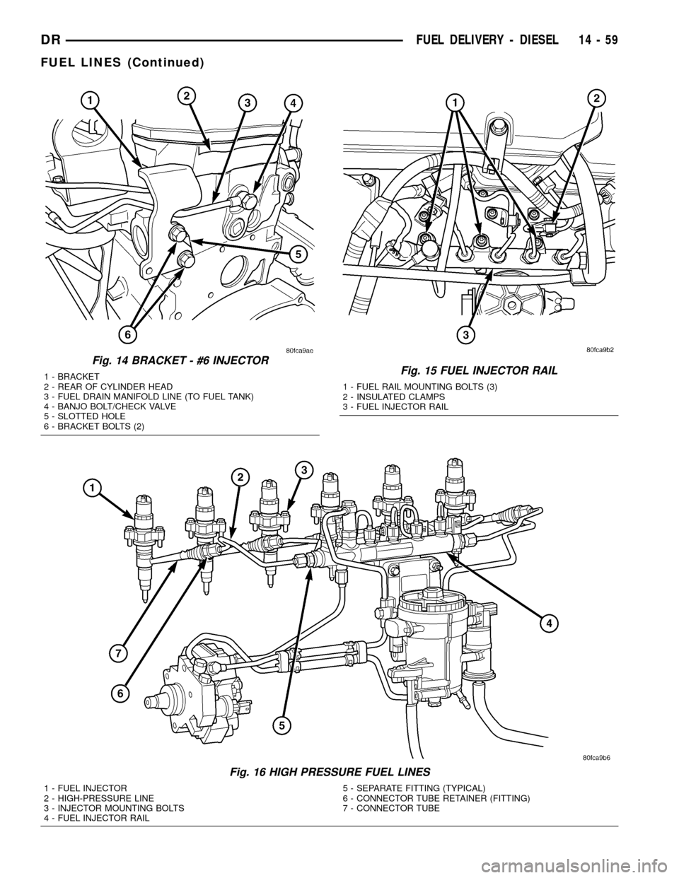
Fig. 16 HIGH PRESSURE FUEL LINES
1 - FUEL INJECTOR
2 - HIGH-PRESSURE LINE
3 - INJECTOR MOUNTING BOLTS
4 - FUEL INJECTOR RAIL5 - SEPARATE FITTING (TYPICAL)
6 - CONNECTOR TUBE RETAINER (FITTING)
7 - CONNECTOR TUBE
Fig. 14 BRACKET - #6 INJECTOR
1 - BRACKET
2 - REAR OF CYLINDER HEAD
3 - FUEL DRAIN MANIFOLD LINE (TO FUEL TANK)
4 - BANJO BOLT/CHECK VALVE
5 - SLOTTED HOLE
6 - BRACKET BOLTS (2)Fig. 15 FUEL INJECTOR RAIL
1 - FUEL RAIL MOUNTING BOLTS (3)
2 - INSULATED CLAMPS
3 - FUEL INJECTOR RAIL
DRFUEL DELIVERY - DIESEL 14 - 59
FUEL LINES (Continued)
Page 1629 of 2627
INSTALLATION
All high-pressure fuel lines are of the same length
and inside diameter. Correct high-pressure fuel line
usage and installation is critical to smooth engine
operation.
CAUTION: Anytime a high-pressure line is removed
from the engine, its fuel connector nut at the cylin-
der head must first be retorqued. Refer to Torque
Specifications.
(1) Tighten fuel lines at high pressure injector con-
nector. Refer to Torque Specifications.
(2) Position fuel line support clamp(s) to fuel
line(s). Install clamp nuts/bolts and tighten finger
tight.
(3) Position proper fuel line to proper injector on
engine. Tighten fittings hand tight at both ends of
line.
(4) Tighten fuel lines at fuel rail. Refer to Torque
Specifications.
(5) Tighten clamp/support nuts and bolts. Refer to
Torque Specifications.
(6) Install engine lifting bracket and bolt. Refer to
Torque Specifications.
(7) If fuel line at either #1 or #2 cylinder has been
replaced, install intake manifold air heater elements
to top of intake manifold. Refer to Intake Air Heater
Removal / Installation for procedures.
(8) If fuel line at #6 cylinder has been replaced, tilt
metal bracket upward and tighten 2 bolts at rear of
cylinder head. Refer to Torque Specifications.
(9) Install remaining fuel line support clamps and
bracket bolts at intake manifold. Refer to Torque
Specifications.
(10) Connect both negative battery cables to both
batteries.
(11) Prime fuel system. Refer to Fuel System
Priming.
(12) Check lines/fittings for leaks.
FUEL PRESSURE SENSOR
DESCRIPTION
The fuel pressure sensor is mounted vertically near
the top/center of the fuel rail.
OPERATION
The fuel pressure sensor monitors actual high-
pressure within the fuel rail. An output signal from
this sensor (relating to fuel pressure) is sent to the
Engine Control Module (ECM).
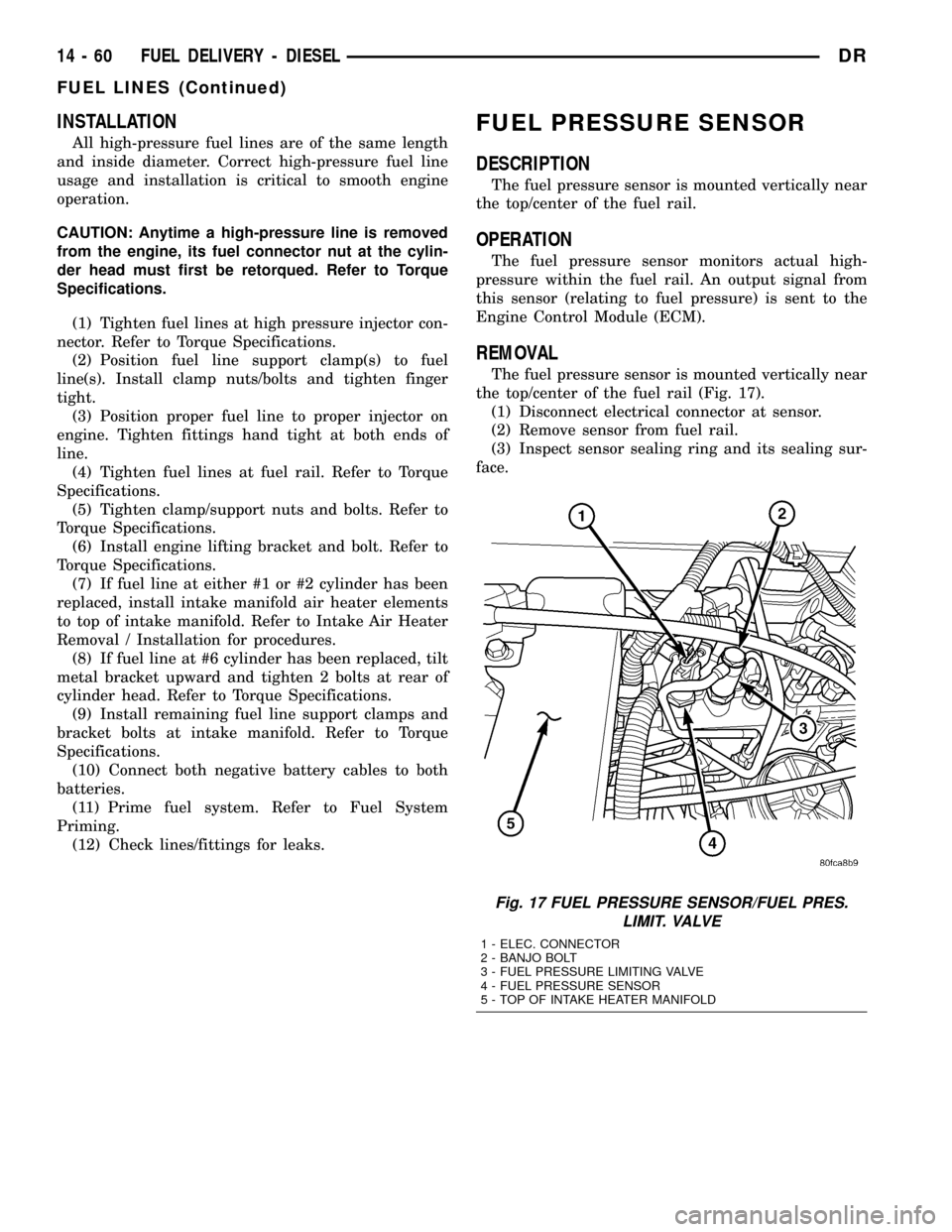
REMOVAL
The fuel pressure sensor is mounted vertically near
the top/center of the fuel rail (Fig. 17).
(1) Disconnect electrical connector at sensor.
(2) Remove sensor from fuel rail.
(3) Inspect sensor sealing ring and its sealing sur-
face.
Fig. 17 FUEL PRESSURE SENSOR/FUEL PRES.
LIMIT. VALVE
1 - ELEC. CONNECTOR
2 - BANJO BOLT
3 - FUEL PRESSURE LIMITING VALVE
4 - FUEL PRESSURE SENSOR
5 - TOP OF INTAKE HEATER MANIFOLD
14 - 60 FUEL DELIVERY - DIESELDR
FUEL LINES (Continued)
Page 1643 of 2627
FUEL CONTROL ACTUATOR
DESCRIPTION
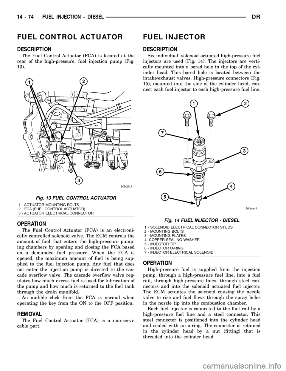
The Fuel Control Actuator (FCA) is located at the
rear of the high-pressure, fuel injection pump (Fig.
13).
OPERATION
The Fuel Control Actuator (FCA) is an electroni-
cally controlled solenoid valve. The ECM controls the
amount of fuel that enters the high-pressure pump-
ing chambers by opening and closing the FCA based
on a demanded fuel pressure. When the FCA is
opened, the maximum amount of fuel is being sup-
plied to the fuel injection pump. Any fuel that does
not enter the injection pump is directed to the cas-
cade overflow valve. The cascade overflow valve reg-
ulates how much excess fuel is used for lubrication of
the pump and how much is returned to the fuel tank
through the drain manifold.
An audible click from the FCA is normal when
operating the key from the ON to the OFF position.
REMOVAL
The Fuel Control Actuator (FCA) is a non-servi-
cable part.
FUEL INJECTOR
DESCRIPTION
Six individual, solenoid actuated high-pressure fuel
injectors are used (Fig. 14). The injectors are verti-
cally mounted into a bored hole in the top of the cyl-
inder head. This bored hole is located between the
intake/exhaust valves. High-pressure connectors (Fig.
15), mounted into the side of the cylinder head, con-
nect each fuel injector to each high-pressure fuel line.
OPERATION
High-pressure fuel is supplied from the injection
pump, through a high-pressure fuel line, into a fuel
rail, through high-pressure lines, through steel con-
nectors and into the solenoid actuated fuel injector.
The ECM actuates the solenoid causing the needle
valve to rise and fuel flows through the spray holes
in the nozzle tip into the combustion chamber.
Each fuel injector is connected to the fuel rail by a
high-pressure fuel line and a steel connector. This
steel connector is positioned into the cylinder head
and sealed with an o-ring. The connector is retained
in the cylinder head by a nut (fitting) that is
threaded into the cylinder head.
Fig. 13 FUEL CONTROL ACTUATOR
1 - ACTUATOR MOUNTING BOLTS
2 - FCA (FUEL CONTROL ACTUATOR)
3 - ACTUATOR ELECTRICAL CONNECTOR
Fig. 14 FUEL INJECTOR - DIESEL
1 - SOLENOID ELECTRICAL CONNECTOR STUDS
2 - MOUNTING BOLTS
3 - MOUNTING PLATES
4- COPPER SEALING WASHER
5 - INJECTOR TIP
6 - INJECTOR O-RING
7 - INJECTOR ELECTRICAL SOLENOID
14 - 74 FUEL INJECTION - DIESELDR