1998 DODGE RAM 1500 steering wheel
[x] Cancel search: steering wheelPage 1158 of 2627
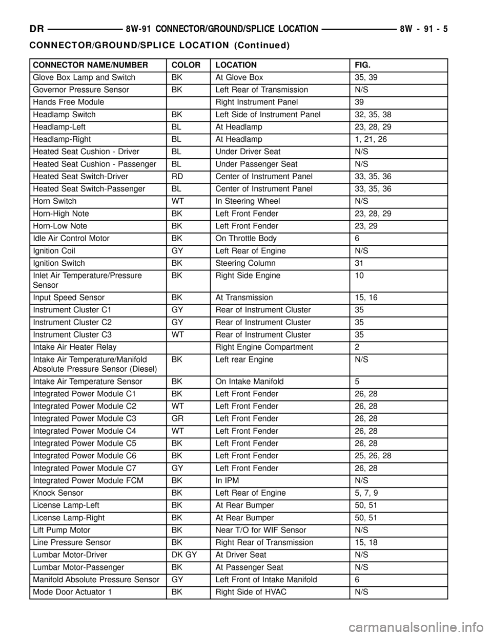
CONNECTOR NAME/NUMBER COLOR LOCATION FIG.
Glove Box Lamp and Switch BK At Glove Box 35, 39
Governor Pressure Sensor BK Left Rear of Transmission N/S
Hands Free Module Right Instrument Panel 39
Headlamp Switch BK Left Side of Instrument Panel 32, 35, 38
Headlamp-Left BL At Headlamp 23, 28, 29
Headlamp-Right BL At Headlamp 1, 21, 26
Heated Seat Cushion - Driver BL Under Driver Seat N/S
Heated Seat Cushion - Passenger BL Under Passenger Seat N/S
Heated Seat Switch-Driver RD Center of Instrument Panel 33, 35, 36
Heated Seat Switch-Passenger BL Center of Instrument Panel 33, 35, 36
Horn Switch WT In Steering Wheel N/S
Horn-High Note BK Left Front Fender 23, 28, 29
Horn-Low Note BK Left Front Fender 23, 29
Idle Air Control Motor BK On Throttle Body 6
Ignition Coil GY Left Rear of Engine N/S
Ignition Switch BK Steering Column 31
Inlet Air Temperature/Pressure
SensorBK Right Side Engine 10
Input Speed Sensor BK At Transmission 15, 16
Instrument Cluster C1 GY Rear of Instrument Cluster 35
Instrument Cluster C2 GY Rear of Instrument Cluster 35
Instrument Cluster C3 WT Rear of Instrument Cluster 35
Intake Air Heater Relay Right Engine Compartment 2
Intake Air Temperature/Manifold
Absolute Pressure Sensor (Diesel)BK Left rear Engine N/S
Intake Air Temperature Sensor BK On Intake Manifold 5
Integrated Power Module C1 BK Left Front Fender 26, 28
Integrated Power Module C2 WT Left Front Fender 26, 28
Integrated Power Module C3 GR Left Front Fender 26, 28
Integrated Power Module C4 WT Left Front Fender 26, 28
Integrated Power Module C5 BK Left Front Fender 26, 28
Integrated Power Module C6 BK Left Front Fender 25, 26, 28
Integrated Power Module C7 GY Left Front Fender 26, 28
Integrated Power Module FCM BK In IPM N/S
Knock Sensor BK Left Rear of Engine 5, 7, 9
License Lamp-Left BK At Rear Bumper 50, 51
License Lamp-Right BK At Rear Bumper 50, 51
Lift Pump Motor BK Near T/O for WIF Sensor N/S
Line Pressure Sensor BK Right Rear of Transmission 15, 18
Lumbar Motor-Driver DK GY At Driver Seat N/S
Lumbar Motor-Passenger BK At Passenger Seat N/S
Manifold Absolute Pressure Sensor GY Left Front of Intake Manifold 6
Mode Door Actuator 1 BK Right Side of HVAC N/S
DR8W-91 CONNECTOR/GROUND/SPLICE LOCATION 8W - 91 - 5
CONNECTOR/GROUND/SPLICE LOCATION (Continued)
Page 1160 of 2627
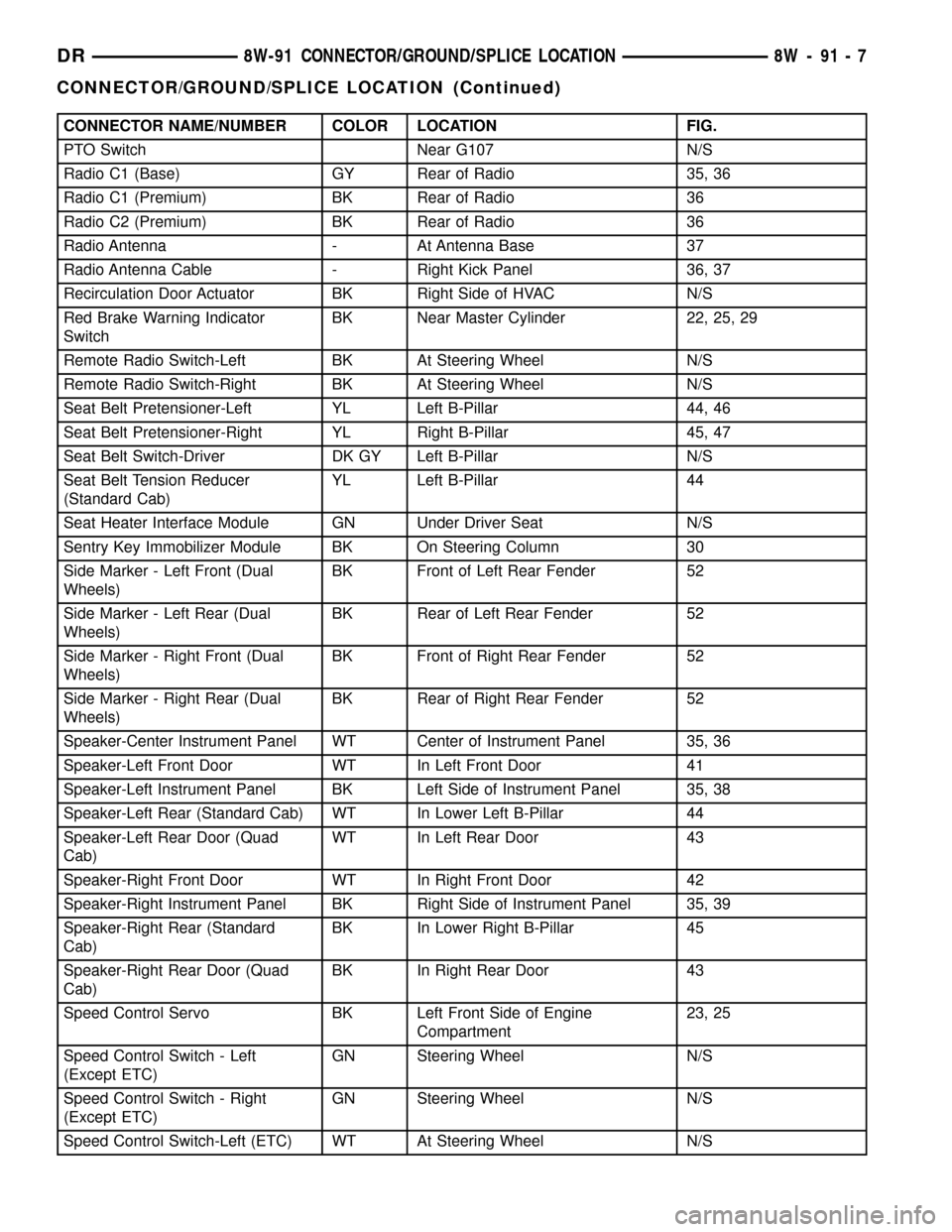
CONNECTOR NAME/NUMBER COLOR LOCATION FIG.
PTO Switch Near G107 N/S
Radio C1 (Base) GY Rear of Radio 35, 36
Radio C1 (Premium) BK Rear of Radio 36
Radio C2 (Premium) BK Rear of Radio 36
Radio Antenna - At Antenna Base 37
Radio Antenna Cable - Right Kick Panel 36, 37
Recirculation Door Actuator BK Right Side of HVAC N/S
Red Brake Warning Indicator
SwitchBK Near Master Cylinder 22, 25, 29
Remote Radio Switch-Left BK At Steering Wheel N/S
Remote Radio Switch-Right BK At Steering Wheel N/S
Seat Belt Pretensioner-Left YL Left B-Pillar 44, 46
Seat Belt Pretensioner-Right YL Right B-Pillar 45, 47
Seat Belt Switch-Driver DK GY Left B-Pillar N/S
Seat Belt Tension Reducer
(Standard Cab)YL Left B-Pillar 44
Seat Heater Interface Module GN Under Driver Seat N/S
Sentry Key Immobilizer Module BK On Steering Column 30
Side Marker - Left Front (Dual
Wheels)BK Front of Left Rear Fender 52
Side Marker - Left Rear (Dual
Wheels)BK Rear of Left Rear Fender 52
Side Marker - Right Front (Dual
Wheels)BK Front of Right Rear Fender 52
Side Marker - Right Rear (Dual
Wheels)BK Rear of Right Rear Fender 52
Speaker-Center Instrument Panel WT Center of Instrument Panel 35, 36
Speaker-Left Front Door WT In Left Front Door 41
Speaker-Left Instrument Panel BK Left Side of Instrument Panel 35, 38
Speaker-Left Rear (Standard Cab) WT In Lower Left B-Pillar 44
Speaker-Left Rear Door (Quad
Cab)WT In Left Rear Door 43
Speaker-Right Front Door WT In Right Front Door 42
Speaker-Right Instrument Panel BK Right Side of Instrument Panel 35, 39
Speaker-Right Rear (Standard
Cab)BK In Lower Right B-Pillar 45
Speaker-Right Rear Door (Quad
Cab)BK In Right Rear Door 43
Speed Control Servo BK Left Front Side of Engine
Compartment23, 25
Speed Control Switch - Left
(Except ETC)GN Steering Wheel N/S
Speed Control Switch - Right
(Except ETC)GN Steering Wheel N/S
Speed Control Switch-Left (ETC) WT At Steering Wheel N/S
DR8W-91 CONNECTOR/GROUND/SPLICE LOCATION 8W - 91 - 7
CONNECTOR/GROUND/SPLICE LOCATION (Continued)
Page 1161 of 2627
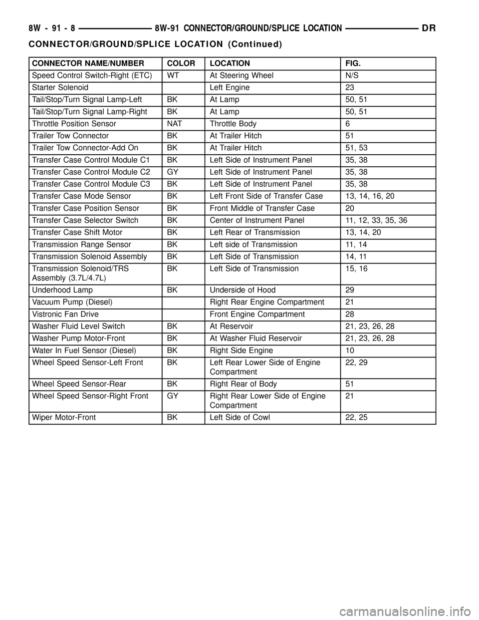
CONNECTOR NAME/NUMBER COLOR LOCATION FIG.
Speed Control Switch-Right (ETC) WT At Steering Wheel N/S
Starter Solenoid Left Engine 23
Tail/Stop/Turn Signal Lamp-Left BK At Lamp 50, 51
Tail/Stop/Turn Signal Lamp-Right BK At Lamp 50, 51
Throttle Position Sensor NAT Throttle Body 6
Trailer Tow Connector BK At Trailer Hitch 51
Trailer Tow Connector-Add On BK At Trailer Hitch 51, 53
Transfer Case Control Module C1 BK Left Side of Instrument Panel 35, 38
Transfer Case Control Module C2 GY Left Side of Instrument Panel 35, 38
Transfer Case Control Module C3 BK Left Side of Instrument Panel 35, 38
Transfer Case Mode Sensor BK Left Front Side of Transfer Case 13, 14, 16, 20
Transfer Case Position Sensor BK Front Middle of Transfer Case 20
Transfer Case Selector Switch BK Center of Instrument Panel 11, 12, 33, 35, 36
Transfer Case Shift Motor BK Left Rear of Transmission 13, 14, 20
Transmission Range Sensor BK Left side of Transmission 11, 14
Transmission Solenoid Assembly BK Left Side of Transmission 14, 11
Transmission Solenoid/TRS
Assembly (3.7L/4.7L)BK Left Side of Transmission 15, 16
Underhood Lamp BK Underside of Hood 29
Vacuum Pump (Diesel) Right Rear Engine Compartment 21
Vistronic Fan Drive Front Engine Compartment 28
Washer Fluid Level Switch BK At Reservoir 21, 23, 26, 28
Washer Pump Motor-Front BK At Washer Fluid Reservoir 21, 23, 26, 28
Water In Fuel Sensor (Diesel) BK Right Side Engine 10
Wheel Speed Sensor-Left Front BK Left Rear Lower Side of Engine
Compartment22, 29
Wheel Speed Sensor-Rear BK Right Rear of Body 51
Wheel Speed Sensor-Right Front GY Right Rear Lower Side of Engine
Compartment21
Wiper Motor-Front BK Left Side of Cowl 22, 25
8W - 91 - 8 8W-91 CONNECTOR/GROUND/SPLICE LOCATIONDR
CONNECTOR/GROUND/SPLICE LOCATION (Continued)
Page 1458 of 2627
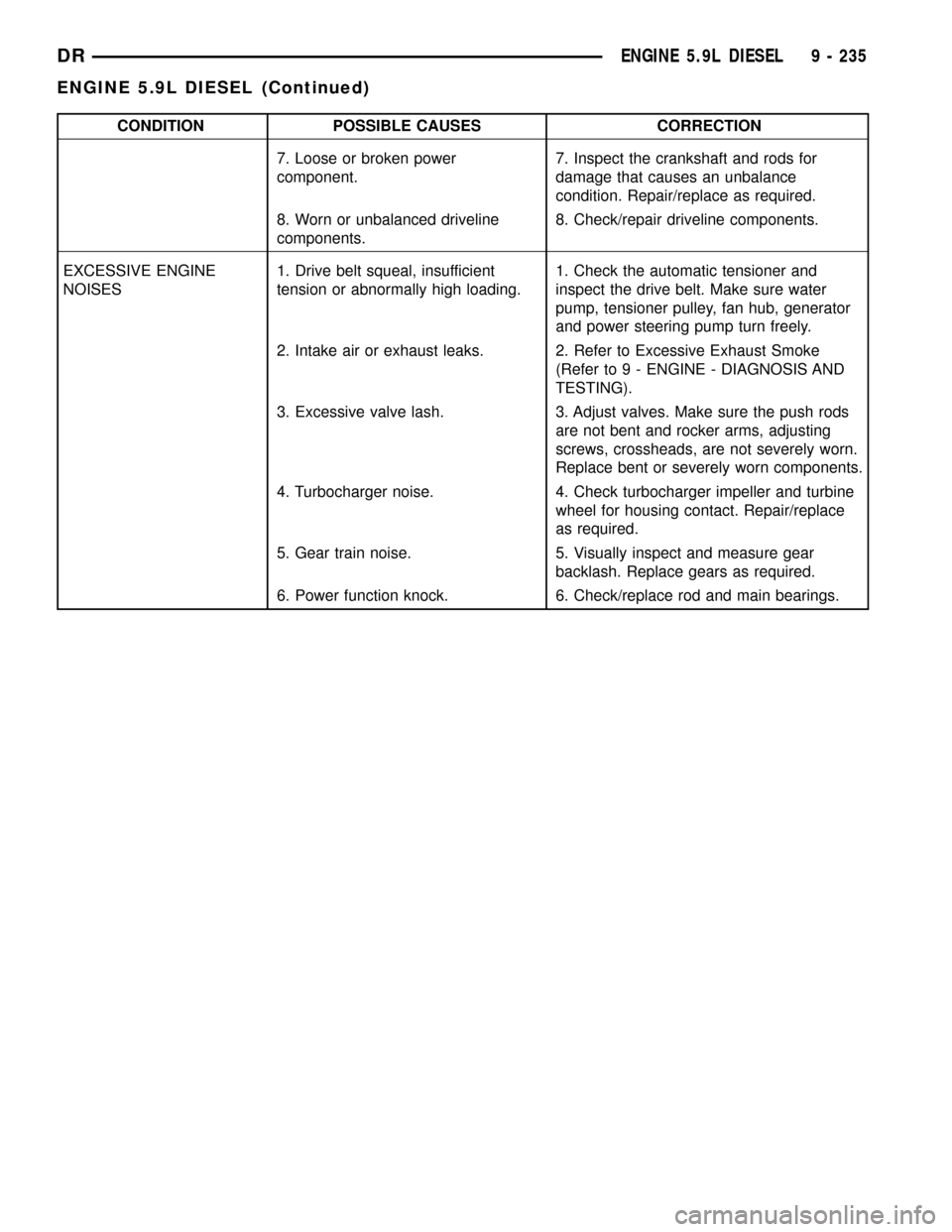
CONDITION POSSIBLE CAUSES CORRECTION
7. Loose or broken power
component.7. Inspect the crankshaft and rods for
damage that causes an unbalance
condition. Repair/replace as required.
8. Worn or unbalanced driveline
components.8. Check/repair driveline components.
EXCESSIVE ENGINE
NOISES1. Drive belt squeal, insufficient
tension or abnormally high loading.1. Check the automatic tensioner and
inspect the drive belt. Make sure water
pump, tensioner pulley, fan hub, generator
and power steering pump turn freely.
2. Intake air or exhaust leaks. 2. Refer to Excessive Exhaust Smoke
(Refer to 9 - ENGINE - DIAGNOSIS AND
TESTING).
3. Excessive valve lash. 3. Adjust valves. Make sure the push rods
are not bent and rocker arms, adjusting
screws, crossheads, are not severely worn.
Replace bent or severely worn components.
4. Turbocharger noise. 4. Check turbocharger impeller and turbine
wheel for housing contact. Repair/replace
as required.
5. Gear train noise. 5. Visually inspect and measure gear
backlash. Replace gears as required.
6. Power function knock. 6. Check/replace rod and main bearings.
DRENGINE 5.9L DIESEL 9 - 235
ENGINE 5.9L DIESEL (Continued)
Page 1464 of 2627
(10) Drain engine oil. Remove and discard the oil
filter (Refer to 9 - ENGINE/LUBRICATION/OIL FIL-
TER - REMOVAL).
(11) Install the drain plug. Tighten the plug to 50
N´m (37 ft. lbs.) torque.
(12) Install a new oil filter (Refer to 9 - ENGINE/
LUBRICATION/OIL FILTER - INSTALLATION).
(13) Fill engine crankcase with the specified
amount and grade of oil (Refer to LUBRICATION &
MAINTENANCE/FLUID TYPES - SPECIFICA-
TIONS).
(14) Connect the negative cable(s) to the battery.
(15) Start the engine and check for any leaks.
REMOVAL
REMOVAL - ENGINE
(1) Disconnect both battery negative cables.
(2) Disconnect engine grid heater harness at grid
heater relays.
(3) Disconnect electrical connections from rear of
alternator.
(4) Recover A/C refrigerant. (Refer to 24 - HEAT-
ING & AIR CONDITIONING/PLUMBING - STAN-
DARD PROCEDURE).
(5) Raise vehicle on a hoist.
(6) Drain engine coolant (Refer to 7 - COOLING -
STANDARD PROCEDURE).
(7) Remove engine oil drain plug and drain engine
oil.
(8) Reinstall drain plug. Tighten to 50N´m (37 ft.
lbs.) torque.
(9) Lower the vehicle.
(10) Remove fan/drive assembly. Refer to Section 7
± Fan/Drive Removal
(11) Remove radiator upper hose.
(12) Remove upper fan shroud mounting bolts.
(13) Disconnect the coolant recovery bottle hose
from the radiator fill neck and remove bottle.
(14) Using a 36mm wrench, remove viscous fan/
drive assembly. (Refer to 7 - COOLING/ENGINE/RA-
DIATOR FAN - REMOVAL).
(15) Remove cooling fan and shroud together.
(16) Disconnect heater core supply and return
hoses from the cylinder head fitting and coolant pipe.
(17) Raise vehicle on a hoist.
(18) Remove transmission and transfer case (if
equipped).
(19) Disconnect exhaust pipe from turbocharger
extension pipe.
(20) Disconnect engine harness to vehicle harness
connectors.
(21) Remove starter motor (Refer to 8 - ELECTRI-
CAL/STARTING/STARTER MOTOR - REMOVAL).(22) Remove flywheel/flexplate.
(23) Remove transmission adapter
(24) Disconnect A/C suction/discharge hose from
the rear of the A/C compressor.
(25) Lower vehicle.
(26) Disconnect lower radiator hose from radiator
outlet.
(27) Automatic transmission models:
(28) Disconnect transmission oil cooler lines from
in front of radiator using special tool #6931
(29) Remove radiator. (Refer to 7 - COOLING/EN-
GINE/RADIATOR - REMOVAL).
(30) If A/C equipped, disconnect A/C condenser
refrigerant lines.
(31) Disconnect charge air cooler piping.
(32) Remove charge air cooler mounting bolts.
(33) Remove charge air cooler (and A/C condenser
if equipped) from vehicle.
(34) Remove damper and speed indicator ring from
front of engine.
(35) Disconnect engine block heater connector.
(36) Disconnect A/C compressor and pressure sen-
sor electrical connectors.
(37) Remove the passenger battery ground cable
from the engine block. Remove the driver side bat-
tery ground cable from the engine block.
(38) Remove power steering pump from engine by
removing 3 bolts.
(39) Remove accelerator linkage cover.
(40) Disconnect cables from on-engine APPS.
(41) Disconnect the ECM power connector.
(42) Disconnect the ECM ground wire from the
hydroform screw.
(43) Disconnect the fuel supply and return hoses.
(44) Remove the cylinder head cover. (Refer to 9 -
ENGINE/CYLINDER HEAD/CYLINDER HEAD
COVER(S) - REMOVAL).
(45) Disconnect the 3 injector harness connectors
at the rocker housing. Disconnect the wire harnesses
from the injectors.
(46) Remove the rear engine lift bracket.
(47) Remove cylinder #4, #5, and #6 intake and
exhaust rocker arms, pedestals, and push tubes. Note
the original location for re-assembly.
(48) Loosen #6 fuel line shield bolts and rotate
shield out of the way.
(49) Remove cylinder #5 and #6 high pressure fuel
lines. Remove the fuel connector tube nut and fuel
connector tube. Remove cylinder #5 and #6 fuel injec-
tor.
(50) Remove rocker housing.
DRENGINE 5.9L DIESEL 9 - 241
ENGINE 5.9L DIESEL (Continued)
Page 1466 of 2627
(8) Replace injector o-ring and sealing washer on
injectors #5 and #6. Install injectors and torque using
the following steps:
²Step 1ÐInstall injector hold-down capscrews
and torque to 5 N´m (44 in. lbs.) torque.
²Step 2ÐLoosen injector hold-down capscrews.
²Step 3ÐInstall HPC connector tube and nut.
Torque nut to 15 N´m (11 ft. lbs.) torque.
²Step 4ÐTorque injector hold-down capscrews to
10 N´m (89 in. lbs.) torque.
²Step 5ÐTorque HPC connector tube nut to 50
N´m (37 ft. lbs.) torque.
(9) Install #5 and #6 high pressure fuel lines. Fol-
low correct torque sequence per section 14. Torque
fuel line fittings to 30 N-m (22 ft-lb). Torque brace
capscrew to 24 N-m (18 ft-lb).
(10) Install rear engine lift bracket. Torque to 77
N-m (57 ft-lb).
(11) Install push tubes, rocker arms, and pedestals
for cylinders #4, #5, and #6. Torque the mounting
bolts to 36 N-m (27 ft-lbs).
(12) Reset valve lash on cylinders #4, #5, and #6.
Torque adjusting nuts to 24 N-m (18 ft-lbs).
(13) Install cylinder head cover. Torque to 24 N-m
(18 ft-lbs).(Refer to 9 - ENGINE/CYLINDER HEAD -
INSTALLATION).
(14) Connect breather tube and lube oil drain tube
to breather housing cover. Install breather housing.
Torque capscrews to 24 N-m (18 ft-lbs)
(15) Connect fuel supply and return hoses.
(16) Connect ECM ground to hydroform screw.
Connect ECM power connector.
(17) Install the APPS cable(s) to the APPS. Install
the throttle linkage cover.
(18) Install the power steering pump.
(19) Install the damper and speed indicator ring.
Torque to 40 N-m (30 ft-lb) plus 60 degrees.
(20) Connect the engine block heater connection.
(21) Connect the A/C compressor and pressure sen-
sor connectors
(22) Install the charge air cooler and a/c condenser
(if equipped). Install and tighten the charge air
cooler mounting bolts to 2 N-m (17 in-lbs).
(23) Connect the charge air cooler piping. Torque
all clamps to 8 N-m (72 in-lbs).
(24) Connect the a/c refrigerant lines to the a/c
condenser (if equipped).
(25) Install the radiator upper support panel.
(26) Install radiator.
(27) Connect the transmission quick-connect oil
cooler lines.(28) Raise vehicle.
(29) Connect a/c compressor suction/discharge hose
(if equipped).
(30) Install the radiator lower hose and clamps.
(31) Install the battery negative cables to the
engine block on the driver and passenger side.
(32) Install the transmission adapter with a new
camshaft rectangular ring seal. Torque to 77 N-m (57
ft-lb).
(33) Install the flywheel/flexplate. Torque to 137
N-m (101 ft-lb).
(34) Install the starter motor. Torque to 43 N-m
(32 ft-lb). (Refer to 8 - ELECTRICAL/STARTING/
STARTER MOTOR - INSTALLATION).
(35) Connect engine to vehicle harness connectors.
(36) Install transmission and transfer case (if
equipped).
(37) Connect the exhaust pipe to the turbocharger
elbow.
(38) Connect the transmission auxiliary oil cooler
lines (if equipped).
(39) Lower the vehicle.
(40) Connect the heater core supply and return
hoses.
(41) Install the cooling fan and upper fan shroud
at the same time. (Refer to 7 - COOLING/ENGINE/
RADIATOR FAN - INSTALLATION).
(42) Install the coolant recovery bottle.
(43) Install the windshield washer bottle.
(44) Install the upper radiator hose and clamps.
(45) Raise vehicle.
(46) Connect electronically controlled fan drive
wire harness. Install lower radiator fan shroud.
(47) Change oil filter and install new engine oil.
(48) Fill the cooling system with coolant. (Refer to
7 - COOLING - STANDARD PROCEDURE).
(49) Connect grid heater harness at grid heater
relays.
(50) Connect electrical connections to rear of alter-
nator.
(51) Start the engine and inspect for engine oil,
coolant, and fuel leaks.
INSTALLATIONÐCRANKCASE BREATHER
(1) Install a new o-ring onto the breather element.
(2) Lubricate o-ring and install into cylinder head
cover. Torque capscrews to 10 N´m (89 in. lbs.).
(3) Connect breather tube and lube oil drain tube.
(4) Install breather cover (Fig. 4). Torque to 24
N´m (18 ft. lbs.)
(5) Install oil fill cap.
DRENGINE 5.9L DIESEL 9 - 243
ENGINE 5.9L DIESEL (Continued)
Page 1499 of 2627
(6) Apply a bead of MopartSilicone Rubber Adhe-
sive Sealant or equivalent to the gear housing cover
sealing surface.
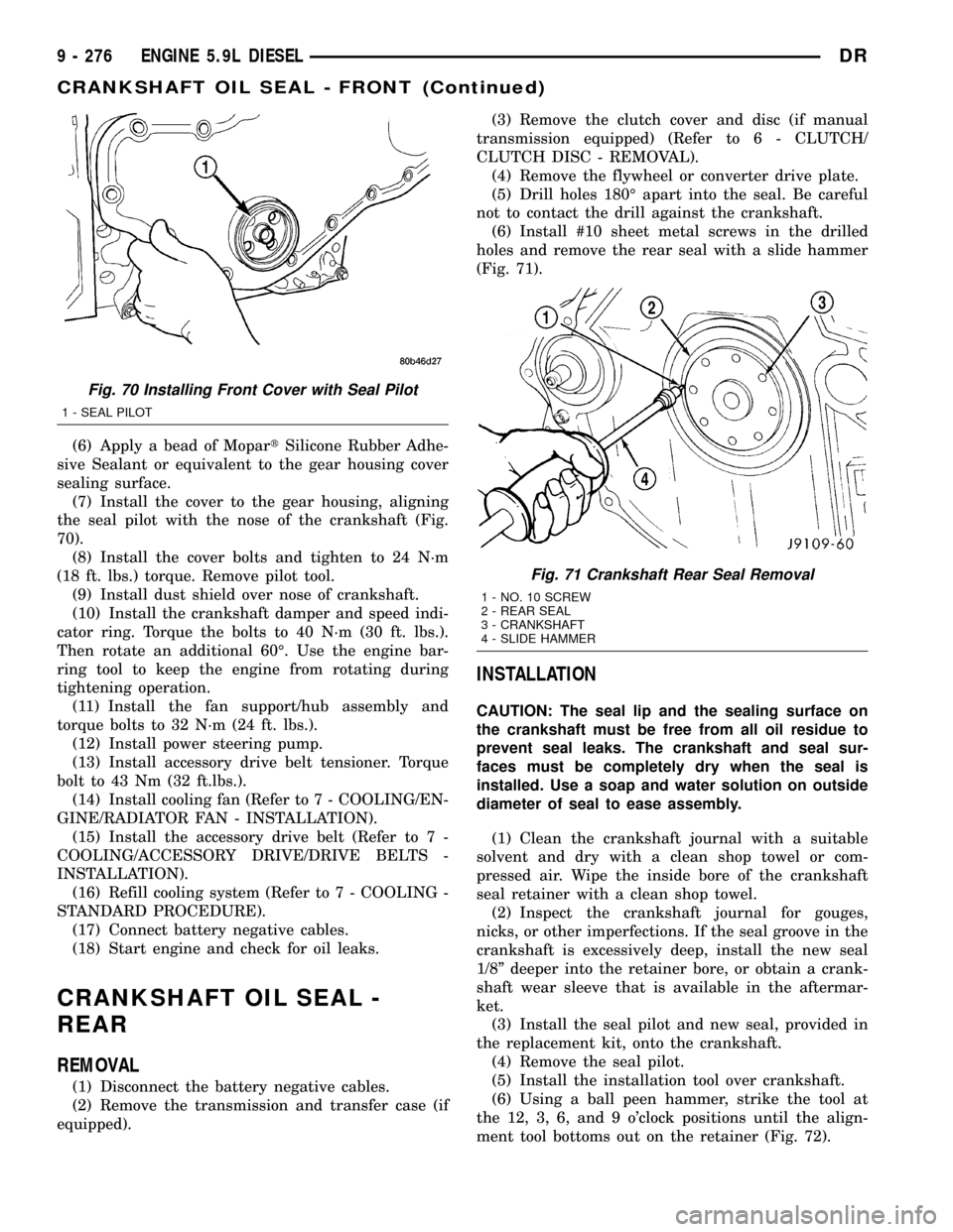
(7) Install the cover to the gear housing, aligning
the seal pilot with the nose of the crankshaft (Fig.
70).
(8) Install the cover bolts and tighten to 24 N´m
(18 ft. lbs.) torque. Remove pilot tool.
(9) Install dust shield over nose of crankshaft.
(10) Install the crankshaft damper and speed indi-
cator ring. Torque the bolts to 40 N´m (30 ft. lbs.).
Then rotate an additional 60É. Use the engine bar-
ring tool to keep the engine from rotating during
tightening operation.
(11) Install the fan support/hub assembly and
torque bolts to 32 N´m (24 ft. lbs.).
(12) Install power steering pump.
(13) Install accessory drive belt tensioner. Torque
bolt to 43 Nm (32 ft.lbs.).
(14) Install cooling fan (Refer to 7 - COOLING/EN-
GINE/RADIATOR FAN - INSTALLATION).
(15) Install the accessory drive belt (Refer to 7 -
COOLING/ACCESSORY DRIVE/DRIVE BELTS -
INSTALLATION).
(16) Refill cooling system (Refer to 7 - COOLING -
STANDARD PROCEDURE).
(17) Connect battery negative cables.
(18) Start engine and check for oil leaks.
CRANKSHAFT OIL SEAL -
REAR
REMOVAL
(1) Disconnect the battery negative cables.
(2) Remove the transmission and transfer case (if
equipped).(3) Remove the clutch cover and disc (if manual
transmission equipped) (Refer to 6 - CLUTCH/
CLUTCH DISC - REMOVAL).
(4) Remove the flywheel or converter drive plate.
(5) Drill holes 180É apart into the seal. Be careful
not to contact the drill against the crankshaft.
(6) Install #10 sheet metal screws in the drilled
holes and remove the rear seal with a slide hammer
(Fig. 71).
INSTALLATION
CAUTION: The seal lip and the sealing surface on
the crankshaft must be free from all oil residue to
prevent seal leaks. The crankshaft and seal sur-
faces must be completely dry when the seal is
installed. Use a soap and water solution on outside
diameter of seal to ease assembly.
(1) Clean the crankshaft journal with a suitable
solvent and dry with a clean shop towel or com-
pressed air. Wipe the inside bore of the crankshaft
seal retainer with a clean shop towel.
(2) Inspect the crankshaft journal for gouges,
nicks, or other imperfections. If the seal groove in the
crankshaft is excessively deep, install the new seal
1/8º deeper into the retainer bore, or obtain a crank-
shaft wear sleeve that is available in the aftermar-
ket.
(3) Install the seal pilot and new seal, provided in
the replacement kit, onto the crankshaft.
(4) Remove the seal pilot.
(5) Install the installation tool over crankshaft.
(6) Using a ball peen hammer, strike the tool at
the 12, 3, 6, and 9 o'clock positions until the align-
ment tool bottoms out on the retainer (Fig. 72).
Fig. 70 Installing Front Cover with Seal Pilot
1 - SEAL PILOT
Fig. 71 Crankshaft Rear Seal Removal
1 - NO. 10 SCREW
2 - REAR SEAL
3 - CRANKSHAFT
4 - SLIDE HAMMER
9 - 276 ENGINE 5.9L DIESELDR
CRANKSHAFT OIL SEAL - FRONT (Continued)
Page 1656 of 2627
STEERING
TABLE OF CONTENTS
page page
STEERING
DESCRIPTION..........................1
OPERATION............................1
DIAGNOSIS AND TESTING
DIAGNOSIS AND TESTING - POWER
STEERING SYSTEM....................2
DIAGNOSIS AND TESTING - POWER
STEERING FLOW AND PRESSURE........4
SPECIAL TOOLS
STEERING...........................5COLUMN...............................6
GEAR - INDEPENDENT FRONT SUSPENSION..17
GEAR - LINK/COIL.......................20
LINKAGE - INDEPENDENT FRONT
SUSPENSION...........................32
LINKAGE - LINK/COIL....................34
PUMP.................................39
STEERING
DESCRIPTION
CAUTION: MOPARTATF+4 is to be used in the
power steering system. No other power steering or
automatic transmission fluid is to be used in the
system. Damage may result to the power steering
pump and system if any other fluid is used, and do
not overfill.
Power steering systems consist of:
²Steering column
²Rack and pinion steering gear
²Belt driven hydraulic steering pump
²Pump pressure and return hoses
²Oil Cooler
OPERATION
The steering column shaft is attached to the gear
pinion. The rotation of the pinion moves the gear
rack from side-to-side. This lateral action of the rack
pushes and pulls the tie rods to change the direction
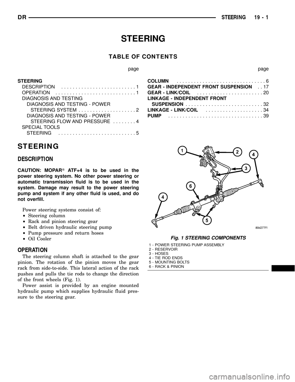
of the front wheels (Fig. 1).
Power assist is provided by an engine mounted
hydraulic pump which supplies hydraulic fluid pres-
sure to the steering gear.
Fig. 1 STEERING COMPONENTS
1 - POWER STEERING PUMP ASSEMBLY
2 - RESERVOIR
3 - HOSES
4 - TIE ROD ENDS
5 - MOUNTING BOLTS
6 - RACK & PINION
DRSTEERING 19 - 1