1998 DODGE RAM 1500 IPM
[x] Cancel search: IPMPage 1216 of 2627
8W-97 POWER DISTRIBUTION
TABLE OF CONTENTS
page page
POWER DISTRIBUTION
DESCRIPTION..........................1
OPERATION............................1
SPECIAL TOOLS
POWER DISTRIBUTION SYSTEMS.........2
CIGAR LIGHTER OUTLET
DESCRIPTION..........................2
OPERATION............................2
DIAGNOSIS AND TESTING - CIGAR LIGHTER
OUTLET.............................2
INTEGRATED POWER MODULE
DESCRIPTION..........................3
OPERATION............................3
REMOVAL.............................3
INSTALLATION..........................4
FRONT CONTROL MODULE
DESCRIPTION..........................5OPERATION............................5
DIAGNOSIS AND TESTING - FRONT
CONTROL MODULE....................5
REMOVAL.............................6
INSTALLATION..........................6
IOD FUSE
DESCRIPTION..........................6
OPERATION............................6
REMOVAL.............................7
INSTALLATION..........................7
POWER OUTLET
DESCRIPTION..........................7
OPERATION............................7
DIAGNOSIS AND TESTING - POWER
OUTLET.............................7
REMOVAL.............................8
INSTALLATION..........................8
POWER DISTRIBUTION
DESCRIPTION
This group covers the various standard and
optional power distribution components used on this
model. The power distribution system for this vehicle
consists of the following components:
²Integrated Power Module (IPM)
²Front Control Module (FCM)
²Power Distribution Center (PDC)
²Power Outlets
²Cigar Lighter Outlets
²Relays
Refer to Wiring Diagrams for complete circuit sche-
matics.
The power distribution system also incorporates
various types of circuit control and protection fea-
tures, including:
²Automatic resetting circuit breakers
²Blade-type fuses
²Cartridge fuses
²Relays
Following are general descriptions of the major
components in the power distribution system. See the
owner's manual in the vehicle glove box for more
information on the features and use of all of the
power distribution system components.
OPERATION
The power distribution system for this vehicle is
designed to provide safe, reliable, and centralized dis-
tribution points for the electrical current required to
operate all of the many standard and optional facto-
ry-installed electrical and electronic powertrain,
chassis, safety, security, comfort and convenience sys-
tems. At the same time, the power distribution sys-
tem was designed to provide ready access to these
electrical distribution points for the vehicle techni-
cian to use when conducting diagnosis and repair of
faulty circuits. The power distribution system can
also prove useful for the sourcing of additional elec-
trical circuits that may be required to provide the
electrical current needed to operate many accessories
that the vehicle owner may choose to have installed
in the aftermarket.
DR8W-97 POWER DISTRIBUTION 8W - 97 - 1
Page 1218 of 2627
INTEGRATED POWER MODULE
DESCRIPTION
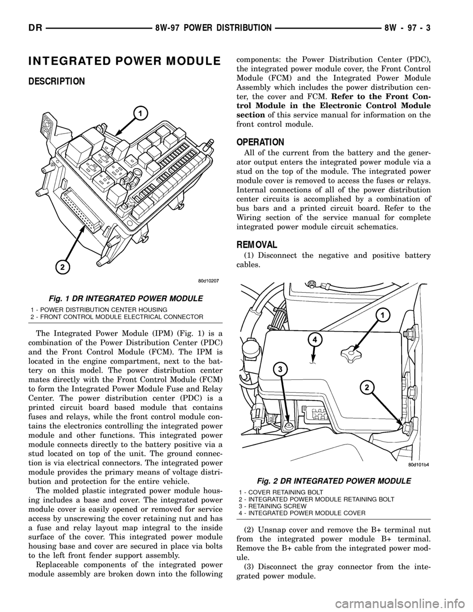
The Integrated Power Module (IPM) (Fig. 1) is a
combination of the Power Distribution Center (PDC)
and the Front Control Module (FCM). The IPM is
located in the engine compartment, next to the bat-
tery on this model. The power distribution center
mates directly with the Front Control Module (FCM)
to form the Integrated Power Module Fuse and Relay
Center. The power distribution center (PDC) is a
printed circuit board based module that contains
fuses and relays, while the front control module con-
tains the electronics controlling the integrated power
module and other functions. This integrated power
module connects directly to the battery positive via a
stud located on top of the unit. The ground connec-
tion is via electrical connectors. The integrated power
module provides the primary means of voltage distri-
bution and protection for the entire vehicle.
The molded plastic integrated power module hous-
ing includes a base and cover. The integrated power
module cover is easily opened or removed for service
access by unscrewing the cover retaining nut and has
a fuse and relay layout map integral to the inside
surface of the cover. This integrated power module
housing base and cover are secured in place via bolts
to the left front fender support assembly.
Replaceable components of the integrated power
module assembly are broken down into the followingcomponents: the Power Distribution Center (PDC),
the integrated power module cover, the Front Control
Module (FCM) and the Integrated Power Module
Assembly which includes the power distribution cen-
ter, the cover and FCM.Refer to the Front Con-
trol Module in the Electronic Control Module
sectionof this service manual for information on the
front control module.
OPERATION
All of the current from the battery and the gener-
ator output enters the integrated power module via a
stud on the top of the module. The integrated power
module cover is removed to access the fuses or relays.
Internal connections of all of the power distribution
center circuits is accomplished by a combination of
bus bars and a printed circuit board. Refer to the
Wiring section of the service manual for complete
integrated power module circuit schematics.
REMOVAL
(1) Disconnect the negative and positive battery
cables.
(2) Unsnap cover and remove the B+ terminal nut
from the integrated power module B+ terminal.
Remove the B+ cable from the integrated power mod-
ule.
(3) Disconnect the gray connector from the inte-
grated power module.
Fig. 1 DR INTEGRATED POWER MODULE
1 - POWER DISTRIBUTION CENTER HOUSING
2 - FRONT CONTROL MODULE ELECTRICAL CONNECTOR
Fig. 2 DR INTEGRATED POWER MODULE
1 - COVER RETAINING BOLT
2 - INTEGRATED POWER MODULE RETAINING BOLT
3 - RETAINING SCREW
4 - INTEGRATED POWER MODULE COVER
DR8W-97 POWER DISTRIBUTION 8W - 97 - 3
Page 1220 of 2627
(3) Connect the electrical connectors by pushing
straight on and rotating the connector arm inboard,
until the connector is firmly locked in place on the
module assembly.
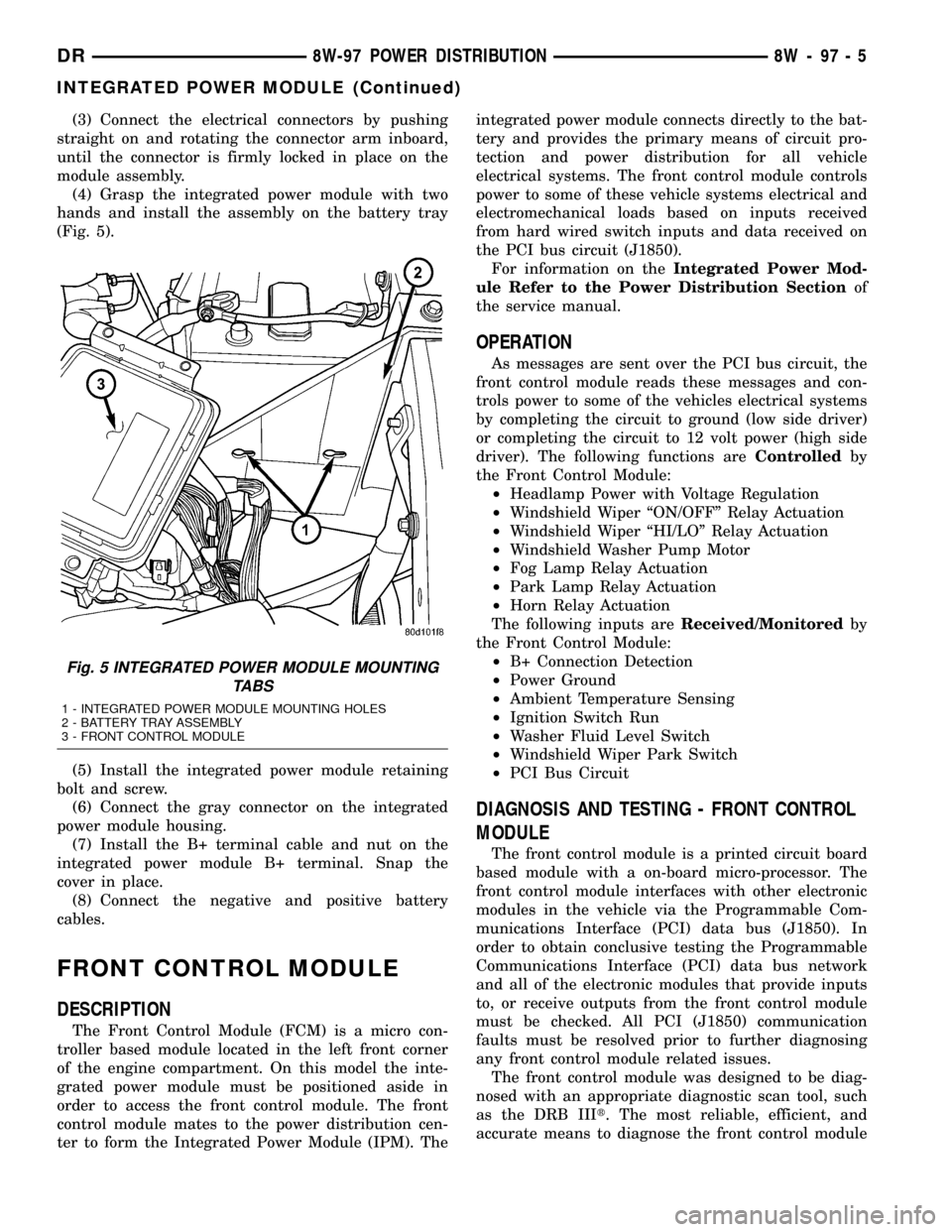
(4) Grasp the integrated power module with two
hands and install the assembly on the battery tray
(Fig. 5).
(5) Install the integrated power module retaining
bolt and screw.
(6) Connect the gray connector on the integrated
power module housing.
(7) Install the B+ terminal cable and nut on the
integrated power module B+ terminal. Snap the
cover in place.
(8) Connect the negative and positive battery
cables.
FRONT CONTROL MODULE
DESCRIPTION
The Front Control Module (FCM) is a micro con-
troller based module located in the left front corner
of the engine compartment. On this model the inte-
grated power module must be positioned aside in
order to access the front control module. The front
control module mates to the power distribution cen-
ter to form the Integrated Power Module (IPM). Theintegrated power module connects directly to the bat-
tery and provides the primary means of circuit pro-
tection and power distribution for all vehicle
electrical systems. The front control module controls
power to some of these vehicle systems electrical and
electromechanical loads based on inputs received
from hard wired switch inputs and data received on
the PCI bus circuit (J1850).
For information on theIntegrated Power Mod-
ule Refer to the Power Distribution Sectionof
the service manual.
OPERATION
As messages are sent over the PCI bus circuit, the
front control module reads these messages and con-
trols power to some of the vehicles electrical systems
by completing the circuit to ground (low side driver)
or completing the circuit to 12 volt power (high side
driver). The following functions areControlledby
the Front Control Module:
²Headlamp Power with Voltage Regulation
²Windshield Wiper ªON/OFFº Relay Actuation
²Windshield Wiper ªHI/LOº Relay Actuation
²Windshield Washer Pump Motor
²Fog Lamp Relay Actuation
²Park Lamp Relay Actuation
²Horn Relay Actuation
The following inputs areReceived/Monitoredby
the Front Control Module:
²B+ Connection Detection
²Power Ground
²Ambient Temperature Sensing
²Ignition Switch Run
²Washer Fluid Level Switch
²Windshield Wiper Park Switch
²PCI Bus Circuit
DIAGNOSIS AND TESTING - FRONT CONTROL
MODULE
The front control module is a printed circuit board
based module with a on-board micro-processor. The
front control module interfaces with other electronic
modules in the vehicle via the Programmable Com-
munications Interface (PCI) data bus (J1850). In
order to obtain conclusive testing the Programmable
Communications Interface (PCI) data bus network
and all of the electronic modules that provide inputs
to, or receive outputs from the front control module
must be checked. All PCI (J1850) communication
faults must be resolved prior to further diagnosing
any front control module related issues.
The front control module was designed to be diag-
nosed with an appropriate diagnostic scan tool, such
as the DRB IIIt. The most reliable, efficient, and
accurate means to diagnose the front control module
Fig. 5 INTEGRATED POWER MODULE MOUNTING
TABS
1 - INTEGRATED POWER MODULE MOUNTING HOLES
2 - BATTERY TRAY ASSEMBLY
3 - FRONT CONTROL MODULE
DR8W-97 POWER DISTRIBUTION 8W - 97 - 5
INTEGRATED POWER MODULE (Continued)
Page 1532 of 2627
(1) Position the catalytic converter onto the
exhaust pipe flange connection. Tighten the nuts to
28 N´m (250 in. lbs.) torque.
(2) Install the muffler onto the catalytic converter
until the alignment tab is inserted into the align-
ment slot.
(3) Install the exhaust clamp at the muffler and
catalytic converter connection. Tighten the clamp
nuts to 54.2 N´m (40 ft. lbs.) torque.
(4) Connect oxygen sensor wiring.
(5) Lower the vehicle.
(6) Start the engine and inspect for exhaust leaks.
Reair exhaust leaks as necessary.
(7) Check the exhaust system for contact with the
body panels. A minimum of 25.4 mm (1.0 in.) is
required between the exhaust system components
and body/frame parts. Make the necessary adjust-
ments, if needed..
INSTALLATION
(1) Assemble converter and clamps loosely in
place.
(2) Install the exhaust pipe onto exhaust mani-
folds, tighten 31 N´m (23 ft. lbs.).
(3) Tighten all clamp nuts to 52.2 N´m (40 ft. lbs.)
torque.
(4) Lower the vehicle.
(5) Start the engine and inspect for exhaust leaks.
Reair exhaust leaks as necessary.
(6) Check the exhaust system for contact with the
body panels. A minimum of 25.4 mm (1.0 in.) is
required between the exhaust system components
and body/frame parts. Make the necessary adjust-
ments, if needed..
EXHAUST PIPE
REMOVAL - 3.7L/4.7L/5.7L
(1) Raise and support the vehicle.
(2) Saturate the bolts and nuts with heat valve
lubricant. Allow 5 minutes for penetration.
(3) Remove exhaust pipe to manifold bolts, retain-
ers and nuts.
(4) Remove the clamp nuts.
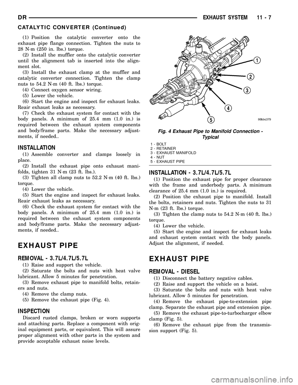
(5) Remove the exhaust pipe (Fig. 4).
INSPECTION
Discard rusted clamps, broken or worn supports
and attaching parts. Replace a component with orig-
inal equipment parts, or equivalent. This will assure
proper alignment with other parts in the system and
provide acceptable exhaust noise levels.
INSTALLATION - 3.7L/4.7L/5.7L
(1) Position the exhaust pipe for proper clearance
with the frame and underbody parts. A minimum
clearance of 25.4 mm (1.0 in.) is required.
(2) Position the exhaust pipe to manifold. Install
the bolts, retainers and nuts. Tighten the nuts to 31
N´m (23 ft. lbs.) torque.
(3) Tighten the clamp nuts to 54.2 N´m (40 ft. lbs.)
torque.
(4) Lower the vehicle.
(5) Start the engine and inspect for exhaust leaks
and exhaust system contact with the body panels.
Adjust the alignment, if needed.
EXHAUST PIPE
REMOVAL - DIESEL
(1) Disconnect the battery negative cables.
(2) Raise and support the vehicle on a hoist.
(3) Saturate the bolts and nuts with heat valve
lubricant. Allow 5 minutes for penetration.
(4) Remove the exhaust pipe-to-extension pipe
clamp. Separate the exhaust pipe and extension pipe.
(5) Remove the exhaust pipe-to-turbocharger elbow
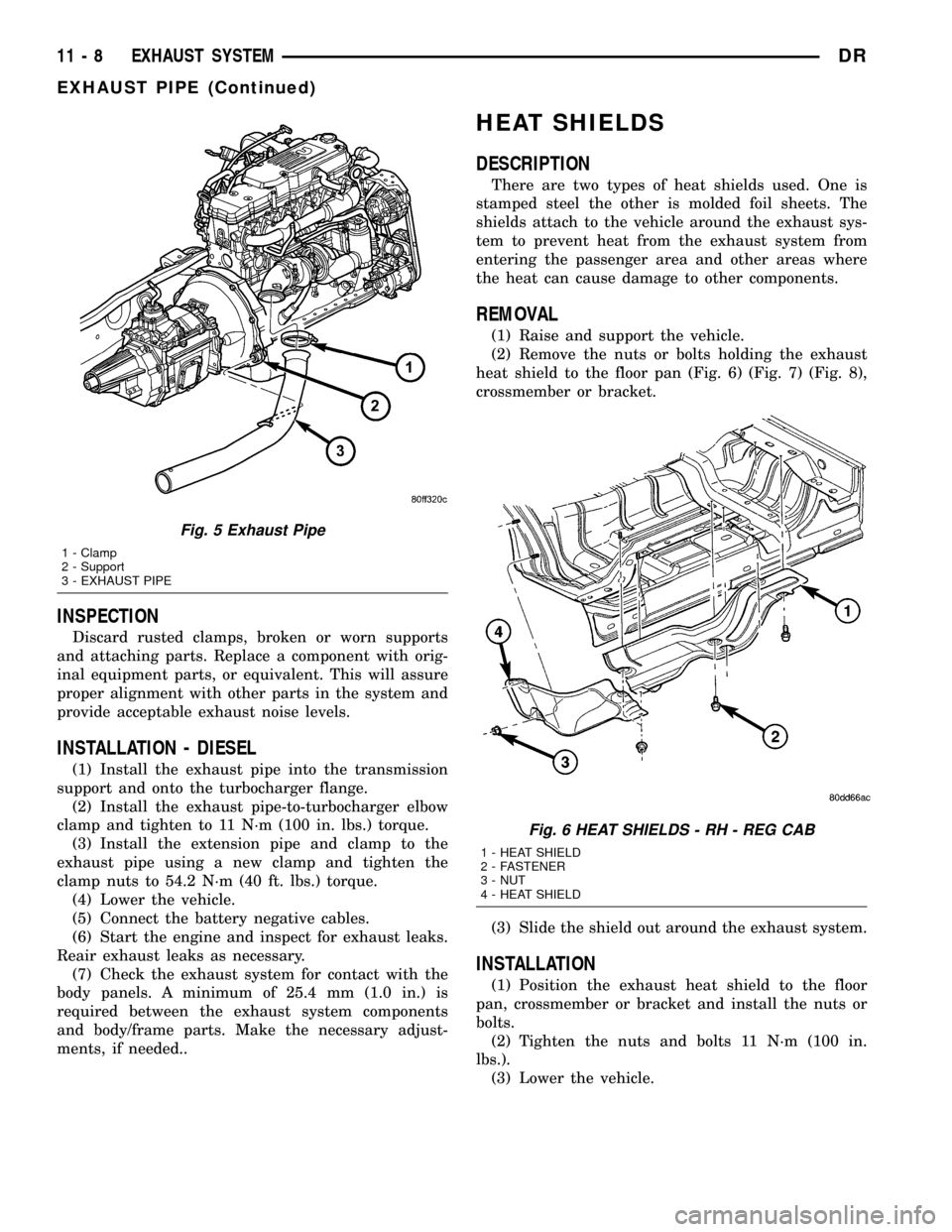
clamp (Fig. 5).
(6) Remove the exhaust pipe from the transmis-
sion support (Fig. 5).
Fig. 4 Exhaust Pipe to Manifold Connection -
Typical
1 - BOLT
2 - RETAINER
3 - EXHAUST MANIFOLD
4 - NUT
5 - EXHAUST PIPE
DREXHAUST SYSTEM 11 - 7
CATALYTIC CONVERTER (Continued)
Page 1533 of 2627
INSPECTION
Discard rusted clamps, broken or worn supports
and attaching parts. Replace a component with orig-
inal equipment parts, or equivalent. This will assure
proper alignment with other parts in the system and
provide acceptable exhaust noise levels.
INSTALLATION - DIESEL
(1) Install the exhaust pipe into the transmission
support and onto the turbocharger flange.
(2) Install the exhaust pipe-to-turbocharger elbow
clamp and tighten to 11 N´m (100 in. lbs.) torque.
(3) Install the extension pipe and clamp to the
exhaust pipe using a new clamp and tighten the
clamp nuts to 54.2 N´m (40 ft. lbs.) torque.
(4) Lower the vehicle.
(5) Connect the battery negative cables.
(6) Start the engine and inspect for exhaust leaks.
Reair exhaust leaks as necessary.
(7) Check the exhaust system for contact with the
body panels. A minimum of 25.4 mm (1.0 in.) is
required between the exhaust system components
and body/frame parts. Make the necessary adjust-
ments, if needed..
HEAT SHIELDS
DESCRIPTION
There are two types of heat shields used. One is
stamped steel the other is molded foil sheets. The
shields attach to the vehicle around the exhaust sys-
tem to prevent heat from the exhaust system from
entering the passenger area and other areas where
the heat can cause damage to other components.
REMOVAL
(1) Raise and support the vehicle.
(2) Remove the nuts or bolts holding the exhaust
heat shield to the floor pan (Fig. 6) (Fig. 7) (Fig. 8),
crossmember or bracket.
(3) Slide the shield out around the exhaust system.
INSTALLATION
(1) Position the exhaust heat shield to the floor
pan, crossmember or bracket and install the nuts or
bolts.
(2) Tighten the nuts and bolts 11 N´m (100 in.
lbs.).
(3) Lower the vehicle.
Fig. 5 Exhaust Pipe
1 - Clamp
2 - Support
3 - EXHAUST PIPE
Fig. 6 HEAT SHIELDS - RH - REG CAB
1 - HEAT SHIELD
2 - FASTENER
3 - NUT
4 - HEAT SHIELD
11 - 8 EXHAUST SYSTEMDR
EXHAUST PIPE (Continued)
Page 1535 of 2627
MUFFLER - 5.9L DIESEL
REMOVAL
(1) Disconnect the battery negative cables.
(2) Raise and support the vehicle.
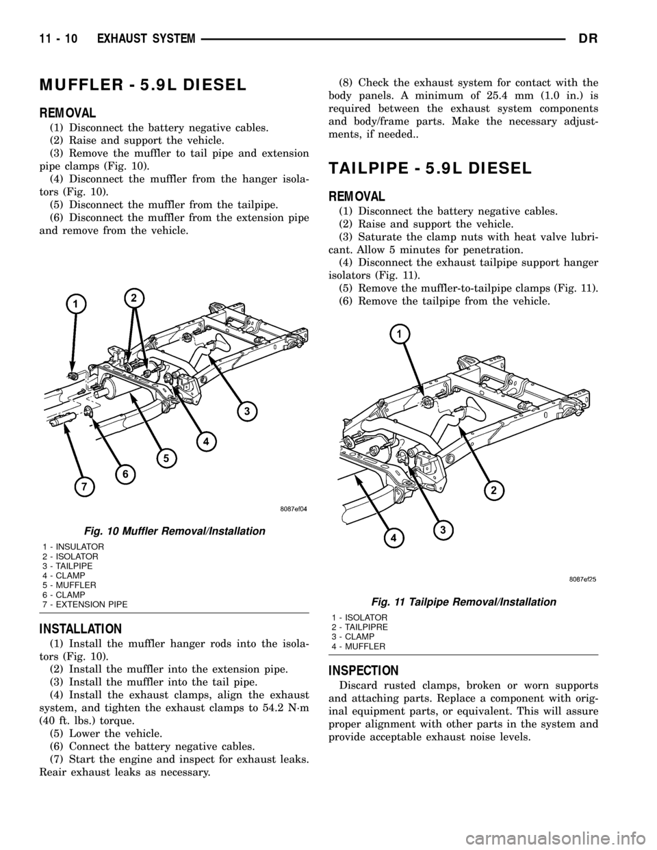
(3) Remove the muffler to tail pipe and extension
pipe clamps (Fig. 10).
(4) Disconnect the muffler from the hanger isola-
tors (Fig. 10).
(5) Disconnect the muffler from the tailpipe.
(6) Disconnect the muffler from the extension pipe
and remove from the vehicle.
INSTALLATION
(1) Install the muffler hanger rods into the isola-
tors (Fig. 10).
(2) Install the muffler into the extension pipe.
(3) Install the muffler into the tail pipe.
(4) Install the exhaust clamps, align the exhaust
system, and tighten the exhaust clamps to 54.2 N´m
(40 ft. lbs.) torque.
(5) Lower the vehicle.
(6) Connect the battery negative cables.
(7) Start the engine and inspect for exhaust leaks.
Reair exhaust leaks as necessary.(8) Check the exhaust system for contact with the
body panels. A minimum of 25.4 mm (1.0 in.) is
required between the exhaust system components
and body/frame parts. Make the necessary adjust-
ments, if needed..
TAILPIPE - 5.9L DIESEL
REMOVAL
(1) Disconnect the battery negative cables.
(2) Raise and support the vehicle.
(3) Saturate the clamp nuts with heat valve lubri-
cant. Allow 5 minutes for penetration.
(4) Disconnect the exhaust tailpipe support hanger
isolators (Fig. 11).
(5) Remove the muffler-to-tailpipe clamps (Fig. 11).
(6) Remove the tailpipe from the vehicle.
INSPECTION
Discard rusted clamps, broken or worn supports
and attaching parts. Replace a component with orig-
inal equipment parts, or equivalent. This will assure
proper alignment with other parts in the system and
provide acceptable exhaust noise levels.
Fig. 10 Muffler Removal/Installation
1 - INSULATOR
2 - ISOLATOR
3 - TAILPIPE
4 - CLAMP
5 - MUFFLER
6 - CLAMP
7 - EXTENSION PIPE
Fig. 11 Tailpipe Removal/Installation
1 - ISOLATOR
2 - TAILPIPRE
3 - CLAMP
4 - MUFFLER
11 - 10 EXHAUST SYSTEMDR
Page 1536 of 2627
INSTALLATION
(1) Install the tailpipe into the muffler.
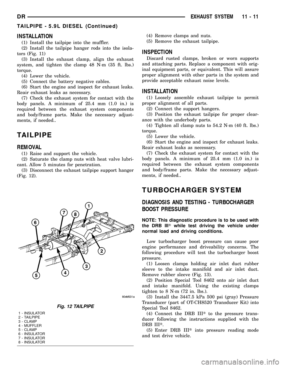
(2) Install the tailpipe hanger rods into the isola-
tors (Fig. 11)
(3) Install the exhaust clamp, align the exhaust
system, and tighten the clamp 48 N´m (35 ft. lbs.)
torque.
(4) Lower the vehicle.
(5) Connect the battery negative cables.
(6) Start the engine and inspect for exhaust leaks.
Reair exhaust leaks as necessary.
(7) Check the exhaust system for contact with the
body panels. A minimum of 25.4 mm (1.0 in.) is
required between the exhaust system components
and body/frame parts. Make the necessary adjust-
ments, if needed..
TAILPIPE
REMOVAL
(1) Raise and support the vehicle.
(2) Saturate the clamp nuts with heat valve lubri-
cant. Allow 5 minutes for penetration.
(3) Disconnect the exhaust tailpipe support hanger
(Fig. 12).(4) Remove clamps and nuts.
(5) Remove the exhaust tailpipe.
INSPECTION
Discard rusted clamps, broken or worn supports
and attaching parts. Replace a component with orig-
inal equipment parts, or equivalent. This will assure
proper alignment with other parts in the system and
provide acceptable exhaust noise levels.
INSTALLATION
(1) Loosely assemble exhaust tailpipe to permit
proper alignment of all parts.
(2) Connect the support hangers.
(3) Position the exhaust tailpipe for proper clear-
ance with the underbody parts.
(4) Tighten all clamp nuts to 54.2 N´m (40 ft. lbs.)
torque.
(5) Lower the vehicle.
(6) Start the engine and inspect for exhaust leaks.
Reair exhaust leaks as necessary.
(7) Check the exhaust system for contact with the
body panels. A minimum of 25.4 mm (1.0 in.) is
required between the exhaust system components
and body/frame parts. Make the necessary adjust-
ments, if needed..
TURBOCHARGER SYSTEM
DIAGNOSIS AND TESTING - TURBOCHARGER
BOOST PRESSURE
NOTE: This diagnostic procedure is to be used with
the DRB IIITwhile test driving the vehicle under
normal load and driving conditions.
Low turbocharger boost pressure can cause poor
engine performance and driveability concerns. The
following procedure will test the turbocharger boost
pressure.
(1) Loosen clamps holding air inlet duct rubber
sleeve to the intake manifold and air inlet duct.
Remove rubber sleeve (Fig. 13).
(2) Position Special Tool 8462 onto air inlet duct
and intake manifold. Using the existing clamps
tighten to 8 N´m (72 in. lbs.).
(3) Install the 3447.5 kPa 500 psi (gray) Pressure
Transducer (part of OT-CH8520 Transducer Kit) into
Special Tool 8462.
(4) Connect the DRB IIItto the pressure trans-
ducer following the instructions supplied with the
DRB IIIt.
(5) Enter DRB IIItinto pressure reading mode
and test drive vehicle.
Fig. 12 TAILPIPE
1 - INSULATOR
2 - TAILPIPE
3 - CLAMP
4 - MUFFLER
5 - CLAMP
6 - INSULATOR
7 - INSULATOR
8 - INSULATOR
DREXHAUST SYSTEM 11 - 11
TAILPIPE - 5.9L DIESEL (Continued)
Page 1547 of 2627
INSTALLATION
(1) Align the holes in the bumpers to the trailer
hitch pins and install the bumper.
(2) Install the support bracket to the hitch bolts,
loosely.
(3) Install the front upper edge to the trailer hitch
bolts and tighten to 54 N´m (40 ft. lbs.).
(4) Install the license plate reinforcement to hitch
bolts and tighten to 54 N´m (40 ft. lbs.).
(5) Tighten the left bumper bracket bolts to 54
N´m (40 ft. lbs.).
(6) Tighten the right bumper bracket bolts to 54
N´m (40 ft. lbs.).
(7) Connect the trailer light connector electrical
connection, if equipped.
(8) Connect the license plate light electrical con-
nectors.
(9) Install the license plate.
FRAME
WARNING
SAFETY PRECAUTIONS AND WARNINGS
WARNING: USE EYE PROTECTION WHEN GRIND-
ING OR WELDING METAL, SERIOUS EYE INJURY
CAN RESULT.
²BEFORE PROCEEDING WITH FRAME REPAIR
INVOLVING GRINDING OR WELDING, VERIFY THAT
VEHICLE FUEL SYSTEM IS NOT LEAKING OR IN
CONTACT WITH REPAIR AREA, PERSONAL INJURY
CAN RESULT.
²DO NOT ALLOW OPEN FLAME OR HEAT AND
METAL SPATTER FROM ARC WELDING, TO CON-
TACT PLASTIC BODY PANELS. FIRE OR EXPLO-
SION CAN RESULT.
²WHEN WELDED FRAME COMPONENTS ARE
REPLACED, ENSURE COMPLETE PENETRATION
WELD IS ACHIEVED DURING INSTALLATION. IF
NOT, DANGEROUS OPERATING CONDITIONS CAN
RESULT.
²STAND CLEAR OF CABLES OR CHAINS ON
PULLING EQUIPMENT DURING FRAME STRAIGHT-
ENING OPERATIONS, PERSONAL INJURY CAN
RESULT.
²DO NOT VENTURE UNDER A HOISTED VEHI-
CLE THAT IS NOT SUPPORTED ON SAFETY
STANDS, PERSONAL INJURY CAN RESULT.
CAUTION: 1500 series Dodge Ram Trucks (2002 and
later) are not designed for snow plow equipment.The front collision repair tips must not be installed
on any truck equipped with a snow plow, or even
intended to be equipped with a snow plow.
CAUTION: Do not reuse damaged fasteners, quality
of repair would be suspect. Failure to use only pro-
duction fasteners or fasteners of equivalent hard-
ness can result in loosening or failure. Do not drill
any holes in the frame that are not specifically out-
lined in this or other, DaimlerChrysler procedure as
frame rail failure can result. When using heat to
straighten frame components do not exceed 566ÉC
(1050ÉF), metal fatigue can result.
STANDARD PROCEDURE
STANDARD PROCEDURE - LIGHT DUTY FRONT
FRAME RAIL TIP REPLACEMENT
CAUTION: This procedure is designed to replace
the front frame rail tips that have been damaged in
the crush initiator zones. Prior to any cutting, the
vehicle must be mounted on the appropriate frame
repair equipment (ªframe rackº), checked with three
dimensional measuring equipment, and the neces-
sary pull corrections made. If damage remains in
the frame beyond the area covered by this service
part after the pull, the frame must be replaced in its
entirety.
NOTE: Procedures for 4X2 and 4X4 are common
except as noted in this procedure.
(1) Before proceding with this repair procedure
review the required service warnings and precau-
tions. (Refer to 13 - FRAME & BUMPERS/FRAME -
WARNING)
(2) Disconnect and isolate the battery negative
cable.
(3) Remove the front wheelhouse splash shield.
(Refer to 23 - BODY/EXTERIOR/FRONT WHEEL-
HOUSE SPLASH SHIELD - REMOVAL)
(4) Remove the bolts and position aside the wire
harness and grounds, if required.
(5) Remove the front bumper. (Refer to 13 -
FRAME & BUMPERS/BUMPERS/FRONT BUMPER
- REMOVAL)
(6) Loosen and lower the stabilizer bar mount and
bar. (Refer to 2 - SUSPENSION/FRONT/STABI-
LIZER BAR - REMOVAL)
13 - 4 FRAMES & BUMPERSDR
REAR BUMPER (Continued)