1998 DODGE RAM 1500 wiring
[x] Cancel search: wiringPage 1217 of 2627

SPECIAL TOOLS
POWER DISTRIBUTION SYSTEMS
CIGAR LIGHTER OUTLET
DESCRIPTION
On models equipped a cigar lighter outlet is
installed to the left of the center stack area in the
lower instrument panel. The cigar lighter outlet is
secured by a snap fit within the bezel.
The cigar lighter outlet, plastic cap and the knob
and heating element unit are available for service
replacement. These components cannot be repaired
and, if faulty or damaged, they must be replaced.
OPERATION
The cigar lighter consists of two major components:
a knob and heating element unit, and the cigar
lighter base or outlet shell. The receptacle shell is
connected to ground, and an insulated contact in the
bottom of the shell is connected to battery current.
The cigar lighter receives battery voltage from a fuse
in the junction block when the ignition switch is in
the Accessory or Run positions.
The cigar lighter knob and heating element are
encased within a spring-loaded housing, which also
features a sliding protective heat shield. When the
knob and heating element are inserted in the outlet
shell, the heating element resistor coil is grounded
through its housing to the outlet shell. If the cigar
lighter knob is pushed inward, the heat shield slides
up toward the knob exposing the heating element,
and the heating element extends from the housing
toward the insulated contact in the bottom of the
outlet shell.
Two small spring-clip retainers are located on
either side of the insulated contact inside the bottom
of the outlet shell. These clips engage and hold the
heating element against the insulated contact longenough for the resistor coil to heat up. When the
heating element is engaged with the contact, battery
current can flow through the resistor coil to ground,
causing the resistor coil to heat.
When the resistor coil becomes sufficiently heated,
excess heat radiates from the heating element caus-
ing the spring-clips to expand. Once the spring-clips
expand far enough to release the heating element,
the spring-loaded housing forces the knob and heat-
ing element to pop back outward to their relaxed
position. When the cigar lighter knob and element
are pulled out of the outlet shell, the protective heat
shield slides downward on the housing so that the
heating element is recessed and shielded around its
circumference for safety.
DIAGNOSIS AND TESTING - CIGAR LIGHTER
OUTLET
For complete circuit diagrams, refer toWiring
Diagrams.
(1) Check the fused B(+) fuse in the integrated
power module. If OK, go to Step 2. If not OK, repair
the shorted circuit or component as required and
replace the faulty fuse.
(2) Turn the ignition switch to the Run position.
Check for battery voltage at the fused B(+) fuse in
the integrated power module. If OK, go to Step 3. If
not OK, repair the open or short as required.
(3) Remove the cigar lighter knob and element
from the cigar lighter outlet shell. Check for continu-
ity between the inside circumference of the cigar
lighter outlet shell and a good ground. there should
be continuity. If OK, go to Step 4. If not OK, go to
Step 5.
(4) Turn the ignition switch to the Run position.
Check for battery voltage at the insulated contact
located at the back of the cigar lighter outlet shell. If
OK, replace the faulty cigar lighter knob and ele-
ment. If not OK, go to Step 5.
(5) Turn the ignition switch to the Off position.
Disconnect and isolate the battery negative cable.
Check for continuity between the ground circuit cav-
ity of the cigar lighter wire harness connector and a
good ground. There should be continuity. If OK, go to
Step 6. If not OK, repair the open ground circuit to
ground as required.
(6) Connect the battery negative cable. Turn the
ignition switch to the Accessory or Run positions.
Check for battery voltage at the fused B(+) circuit
cavity of the cigar lighter wire harness connector. If
OK, replace the faulty cigar lighter outlet. If not OK,
repair the open fused B(+) circuit to the integrated
power module fuse as required.Terminal Pick Kit 6680
8W - 97 - 2 8W-97 POWER DISTRIBUTIONDR
POWER DISTRIBUTION (Continued)
Page 1218 of 2627

INTEGRATED POWER MODULE
DESCRIPTION
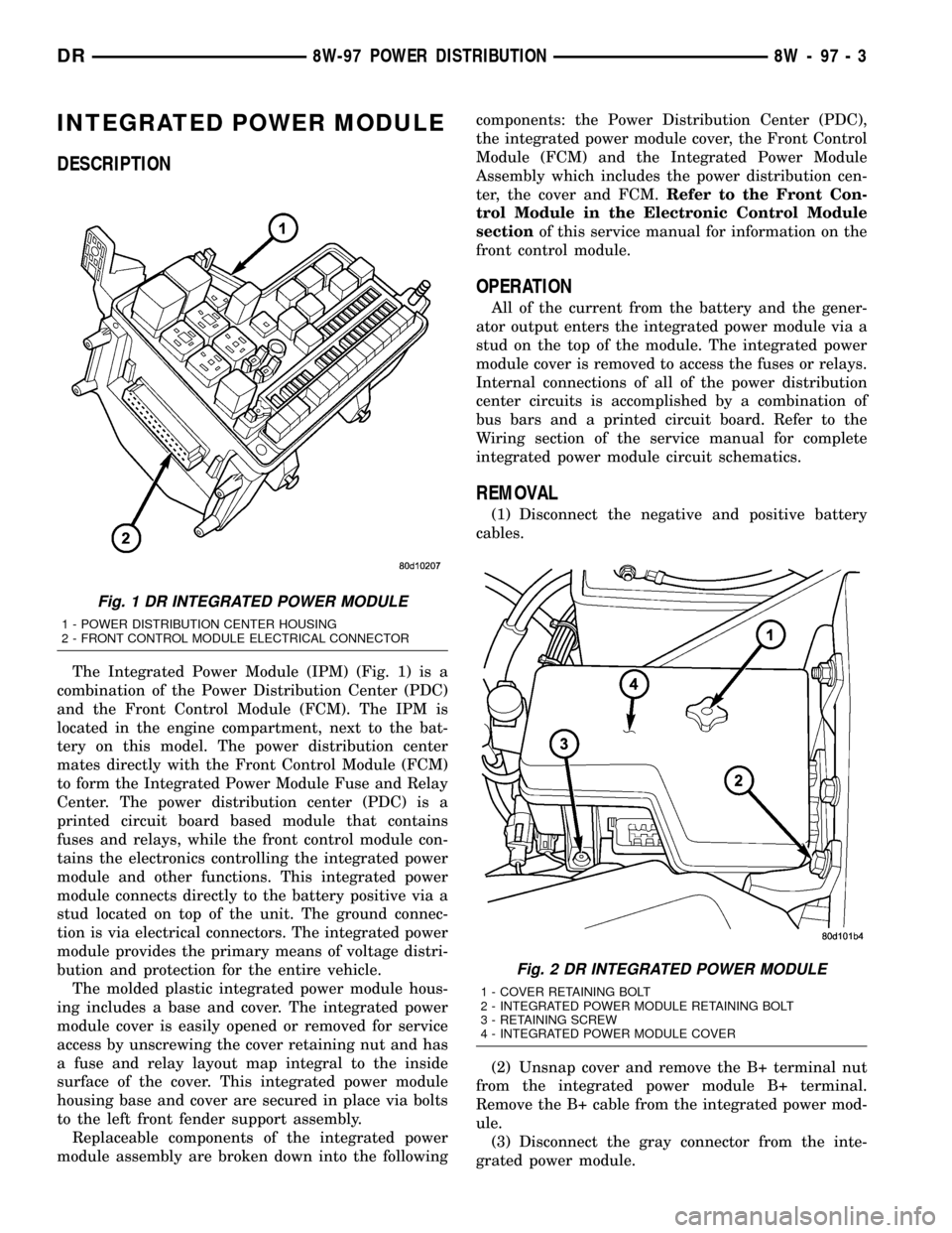
The Integrated Power Module (IPM) (Fig. 1) is a
combination of the Power Distribution Center (PDC)
and the Front Control Module (FCM). The IPM is
located in the engine compartment, next to the bat-
tery on this model. The power distribution center
mates directly with the Front Control Module (FCM)
to form the Integrated Power Module Fuse and Relay
Center. The power distribution center (PDC) is a
printed circuit board based module that contains
fuses and relays, while the front control module con-
tains the electronics controlling the integrated power
module and other functions. This integrated power
module connects directly to the battery positive via a
stud located on top of the unit. The ground connec-
tion is via electrical connectors. The integrated power
module provides the primary means of voltage distri-
bution and protection for the entire vehicle.
The molded plastic integrated power module hous-
ing includes a base and cover. The integrated power
module cover is easily opened or removed for service
access by unscrewing the cover retaining nut and has
a fuse and relay layout map integral to the inside
surface of the cover. This integrated power module
housing base and cover are secured in place via bolts
to the left front fender support assembly.
Replaceable components of the integrated power
module assembly are broken down into the followingcomponents: the Power Distribution Center (PDC),
the integrated power module cover, the Front Control
Module (FCM) and the Integrated Power Module
Assembly which includes the power distribution cen-
ter, the cover and FCM.Refer to the Front Con-
trol Module in the Electronic Control Module
sectionof this service manual for information on the
front control module.
OPERATION
All of the current from the battery and the gener-
ator output enters the integrated power module via a
stud on the top of the module. The integrated power
module cover is removed to access the fuses or relays.
Internal connections of all of the power distribution
center circuits is accomplished by a combination of
bus bars and a printed circuit board. Refer to the
Wiring section of the service manual for complete
integrated power module circuit schematics.
REMOVAL
(1) Disconnect the negative and positive battery
cables.
(2) Unsnap cover and remove the B+ terminal nut
from the integrated power module B+ terminal.
Remove the B+ cable from the integrated power mod-
ule.
(3) Disconnect the gray connector from the inte-
grated power module.
Fig. 1 DR INTEGRATED POWER MODULE
1 - POWER DISTRIBUTION CENTER HOUSING
2 - FRONT CONTROL MODULE ELECTRICAL CONNECTOR
Fig. 2 DR INTEGRATED POWER MODULE
1 - COVER RETAINING BOLT
2 - INTEGRATED POWER MODULE RETAINING BOLT
3 - RETAINING SCREW
4 - INTEGRATED POWER MODULE COVER
DR8W-97 POWER DISTRIBUTION 8W - 97 - 3
Page 1222 of 2627

becomes transparent and the fuse that has been
assigned the IOD designation becomes only another
Fused B(+) circuit fuse.
The IOD fuse can be used by the vehicle owner as
a convenient means of reducing battery depletion
when a vehicle is to be stored for periods not to
exceed about thirty days. However, it must be
remembered that disconnecting the IOD fuse will not
eliminate IOD, but only reduce this normal condition.
If a vehicle will be stored for more than about thirty
days, the battery negative cable should be discon-
nected to eliminate normal IOD; and, the battery
should be tested and recharged at regular intervals
during the vehicle storage period to prevent the bat-
tery from becoming discharged or damaged.
REMOVAL
The Ignition-Off Draw (IOD) fuse is disconnected
from Integrated Power Module fuse cavity # 51 when
the vehicle is shipped from the assembly plant.
Dealer personnel must reconnect the IOD fuse when
the vehicle is being prepared for delivery in order to
restore full electrical system operation.
(1) Turn the ignition switch to the Off position.
(2) Remove the Integrated Power Module cover.
(3) Grasp the outer tabs of the IOD fuse holder
unit in fuse cavity # 51 between the thumb and fore-
finger and pull the unit firmly upward.
(4) Install the Integrated Power Module cover.
INSTALLATION
(1) Turn the ignition switch to the Off position.
(2) Remove the Integrated Power Module cover.
(3) To install the IOD fuse, use a thumb to press
the IOD fuse holder unit in fuse cavity # 51 firmly
into the Integrated Power Module.
(4) Install the Integrated Power Module cover.
POWER OUTLET
DESCRIPTION
Two power outlets are utilized on this model. One
in the instrument panel center lower bezel and the
other in the center console. The power outlet bases
are secured by a snap fit within the instrument
panel or trim panel. A plastic protective cap snaps
into the power outlet base when the power outlet is
not being used, and hangs from the power outlet base
mount by an integral bail strap while the power out-
let is in use.The power outlet receptacle unit and the accessory
power outlet protective cap are available for service.
The power outlet receptacle cannot be repaired and,
if faulty or damaged, it must be replaced.
OPERATION
The power outlet base or receptacle shell is con-
nected to ground, and an insulated contact in the
bottom of the shell is connected to battery current.
The power outlet receives battery voltage from a fuse
in the integrated power module at all times.
While the power outlet is very similar to a cigar
lighter base unit, it does not include the two small
spring-clip retainers inside the bottom of the recepta-
cle shell that are used to secure the cigar lighter
heating element to the insulated contact.
DIAGNOSIS AND TESTING - POWER OUTLET
For complete circuit diagrams, refer toWiring
Diagrams.
(1) Check the fused B(+) fuse in the integrated
power module. If OK, go to Step 2. If not OK, repair
the shorted circuit or component as required and
replace the faulty fuse.
(2) Check for battery voltage at the fused B(+) fuse
in the integrated power module. If OK, go to Step 3.
If not OK, repair the open fused B(+) circuit to the
battery as required.
(3) Remove the plastic protective cap from the
power outlet receptacle. Check for continuity between
the inside circumference of the power outlet recepta-
cle and a good ground. There should be continuity. If
OK, go to Step 4. If not OK, go to Step 5.
(4) Check for battery voltage at the insulated con-
tact located at the back of the power outlet recepta-
cle. If not OK, go to Step 5.
(5) Disconnect and isolate the battery negative
cable. Remove the power outlet receptacle from the
instrument panel. Disconnect the wire harness con-
nector from the power outlet receptacle. Check for
continuity between the ground circuit cavity of the
power outlet wire harness connector and a good
ground. There should be continuity. If OK, go to Step
6. If not OK, repair the open ground circuit to ground
as required.
(6) Connect the battery negative cable. Check for
battery voltage at the fused B(+) circuit cavity of the
power outlet wire harness connector. If OK, replace
the faulty power outlet receptacle. If not OK, repair
the open fused B(+) circuit to the integrated power
module fuse as required.
DR8W-97 POWER DISTRIBUTION 8W - 97 - 7
IOD FUSE (Continued)
Page 1227 of 2627

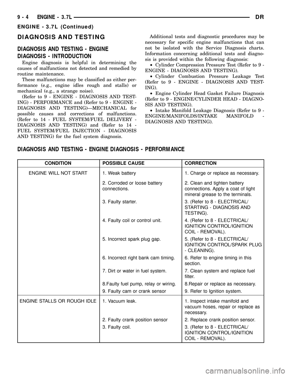
DIAGNOSIS AND TESTING
DIAGNOSIS AND TESTING - ENGINE
DIAGNOSIS - INTRODUCTION
Engine diagnosis is helpful in determining the
causes of malfunctions not detected and remedied by
routine maintenance.
These malfunctions may be classified as either per-
formance (e.g., engine idles rough and stalls) or
mechanical (e.g., a strange noise).
(Refer to 9 - ENGINE - DIAGNOSIS AND TEST-
ING) - PERFORMANCE and (Refer to 9 - ENGINE -
DIAGNOSIS AND TESTING)ÐMECHANICAL for
possible causes and corrections of malfunctions.
(Refer to 14 - FUEL SYSTEM/FUEL DELIVERY -
DIAGNOSIS AND TESTING) and (Refer to 14 -
FUEL SYSTEM/FUEL INJECTION - DIAGNOSIS
AND TESTING) for the fuel system diagnosis.Additional tests and diagnostic procedures may be
necessary for specific engine malfunctions that can
not be isolated with the Service Diagnosis charts.
Information concerning additional tests and diagno-
sis is provided within the following diagnosis:
²Cylinder Compression Pressure Test (Refer to 9 -
ENGINE - DIAGNOSIS AND TESTING).
²Cylinder Combustion Pressure Leakage Test
(Refer to 9 - ENGINE - DIAGNOSIS AND TEST-
ING).
²Engine Cylinder Head Gasket Failure Diagnosis
(Refer to 9 - ENGINE/CYLINDER HEAD - DIAGNO-
SIS AND TESTING).
²Intake Manifold Leakage Diagnosis (Refer to 9 -
ENGINE/MANIFOLDS/INTAKE MANIFOLD -
DIAGNOSIS AND TESTING).
DIAGNOSIS AND TESTING - ENGINE DIAGNOSIS - PERFORMANCE
CONDITION POSSIBLE CAUSE CORRECTION
ENGINE WILL NOT START 1. Weak battery 1. Charge or replace as necessary.
2. Corroded or loose battery
connections.2. Clean and tighten battery
connections. Apply a coat of light
mineral grease to the terminals.
3. Faulty starter. 3. (Refer to 8 - ELECTRICAL/
STARTING - DIAGNOSIS AND
TESTING).
4. Faulty coil or control unit. 4. (Refer to 8 - ELECTRICAL/
IGNITION CONTROL/IGNITION
COIL - REMOVAL).
5. Incorrect spark plug gap. 5. (Refer to 8 - ELECTRICAL/
IGNITION CONTROL/SPARK PLUG
- CLEANING).
6. Incorrect right bank cam timing. 6. Refer to engine timing in this
section.
7. Dirt or water in fuel system. 7. Clean system and replace fuel
filter.
8.Faulty fuel pump, relay or wiring. 8.Repair or replace as necessary.
9. Faulty cam or crank sensor 9. Refer to Ignition system.
ENGINE STALLS OR ROUGH IDLE 1. Vacuum leak. 1. Inspect intake manifold and
vacuum hoses, repair or replace as
necessary.
2. Faulty crank position sensor 2. Replace crank position sensor.
3. Faulty coil. 3. (Refer to 8 - ELECTRICAL/
IGNITION CONTROL/IGNITION
COIL - REMOVAL).
9 - 4 ENGINE - 3.7LDR
ENGINE - 3.7L (Continued)
Page 1234 of 2627

(12) Disconnect heater hoses from heater core and
remove hose assembly.
(13) Disconnect throttle and speed control cables.
(14) Remove upper radiator hose from engine.
(15) Remove lower radiator hose from engine.
(16) Remove radiator/cooling module assembly.
(17) Disconnect the engine to body ground straps
at the left side of cowl.
(18) Disconnect the engine wiring harness at the
following points:
²Intake air temperature (IAT) sensor
²Fuel Injectors
²Throttle Position (TPS) Switch
²Idle Air Control (IAC) Motor
²Engine Oil Pressure Switch
²Engine Coolant Temperature (ECT) Sensor
²Manifold Absolute Pressure MAP) Sensor
²Camshaft Position (CMP) Sensor
²Coil Over Plugs
²Crankshaft Position Sensor
(19) Remove coil over plugs.
(20) Release fuel rail pressure.
(21) Remove fuel rail and secure away from
engine.
NOTE: It is not necessary to release the quick con-
nect fitting from the fuel supply line for engine
removal.
(22) Remove the PCV hose.
(23) Remove the breather hoses.
(24) Remove the vacuum hose for the power brake
booster.
(25) Disconnect knock sensors.
(26) Remove engine oil dipstick tube.
(27) Remove intake manifold.
(28) Install engine lifting fixture,special tool#8247,
using original fasteners from the removed intake
manifold, and fuel rail. Torque to factory specifica-
tions.
NOTE: Recheck bolt torque for engine lift plate
before removing engine.
(29) Secure the left and right engine wiring har-
nesses away from engine.
(30) Raise vehicle.
(31) Disconnect oxygen sensor wiring.
(32) Disconnect crankshaft postion sensor.
(33) Disconnect the engine block heater power
cable, if equipped.
(34) Disconnect the front propshaft at the front
differential and secure out of way.
NOTE: It is necessary to disconnect the front prop-
shaft for access to the starter and left side exhaust
flange.(35) Remove the starter.
(36) Remove the ground straps from the left and
right side of the block.
(37) Disconnect the right and left exhaust pipes at
the manifolds and from the crossover, and remove
from the vehicle.
NOTE: The exhaust clamps at the manifolds cannot
be reused. New clamps must be used or leaks may
occur.
(38) Remove the structural cover.
(39) Remove torque convertor bolts, and mark
location for reassembly.
(40) Remove transmission bellhousing to engine
bolts.
(41) Remove left and right engine mount thru
bolts.
(42) Lower the vehicle.
(43) Support the transmission with a suitable jack.
(44) Connect a suitable engine hoist to the engine
lift plate.
(45) Remove engine from vehicle.
INSTALLATION
(1) Position the engine in the vehicle.
(2) Install both left and right side engine mounts
onto engine.
(3) Raise the vehicle.
(4) Install the transmission bellhousing to engine
mounting bolts. Tighten the bolts to 41 N´m (30ft.
lbs.).
(5) Tighten the engine mount thru bolts.
(6) Install the torque convertor bolts.
(7) Connect the ground straps on the left and right
side of the engine.
(8) Install the starter.
(9) Connect the crankshaft position sensor.
(10) Install the engine block heater power cable, if
equipped.
CAUTION: The structural cover requires a specific
torque sequence. Failure to follow this sequence
may cause severe damage to the cover.
(11) Install the structural cover.
NOTE: New clamps must be used on exhaust man-
ifold flanges. Failure to use new clamps may result
in exhaust leaks.
(12) Install the left and right exhaust pipes.
(13) Connect the left and right oxygen sensors.
(14) Lower vehicle.
(15) Remove the engine lift plate.
(16) Connect the knock sensors.
DRENGINE - 3.7L 9 - 11
ENGINE - 3.7L (Continued)
Page 1235 of 2627

(17) Connect the engine to body ground straps at
the left side of the cowl.
(18) Install the intake manifold.
(19) Install the engine oil dipstick tube.
(20) Install the power brake booster vacuum hose.
(21) Install the breather hoses.
(22) Install the PCV hose.
(23) Install the fuel rail.
(24) Install the coil over plugs.
(25) Connect the engine wiring harness at the fol-
lowing points:
²Intake air temperature (IAT) sensor
²Fuel Injectors
²Throttle Position (TPS) Switch
²Idle Air Control (IAC) Motor
²Engine Oil Pressure Switch
²Engine Coolant Temperature (ECT) Sensor
²Manifold Absolute Pressure MAP) Sensor
²Camshaft Position (CMP) Sensor
²Coil Over Plugs
²Crankshaft Position Sensor
(26) Reinstall the radiator/cooling module assem-
bly.
(27) Connect lower radiator hose.
(28) Connect upper radiator hose.
(29) Connect throttle and speed control cables.
(30) Install the heater hose assembly.
(31) Install coolant recovery bottle.
(32) Install the power steering pump.
(33) Install the generator.
(34) Install the A/C compressor.
(35) Install the drive belt.
(36) Install the fan shroud with the viscous fan
assembly.
(37) Install the radiator core support bracket.
(38) Install the air cleaner assembly.
(39) Refill the engine cooling system.
(40) Recharge the air conditioning.
(41) Install the hood.
(42) Check and fill engine oil.
(43) Connect the battery negative cable.
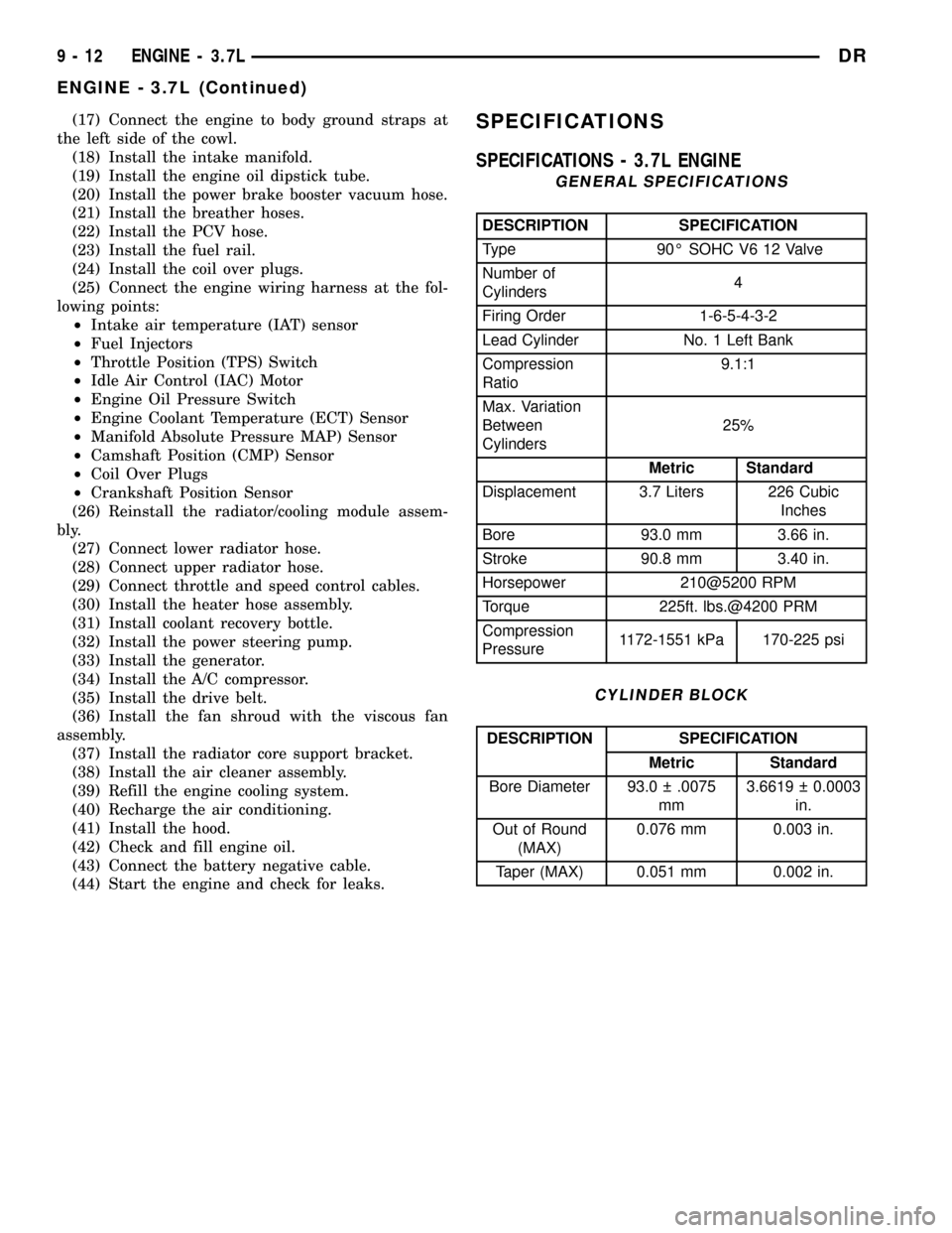
(44) Start the engine and check for leaks.SPECIFICATIONS
SPECIFICATIONS - 3.7L ENGINE
GENERAL SPECIFICATIONS
DESCRIPTION SPECIFICATION
Type 90É SOHC V6 12 Valve
Number of
Cylinders4
Firing Order 1-6-5-4-3-2
Lead Cylinder No. 1 Left Bank
Compression
Ratio9.1:1
Max. Variation
Between
Cylinders25%
Metric Standard
Displacement 3.7 Liters 226 Cubic
Inches
Bore 93.0 mm 3.66 in.
Stroke 90.8 mm 3.40 in.
Horsepower 210@5200 RPM
Torque 225ft. lbs.@4200 PRM
Compression
Pressure1172-1551 kPa 170-225 psi
CYLINDER BLOCK
DESCRIPTION SPECIFICATION
Metric Standard
Bore Diameter 93.0 .0075
mm3.6619 0.0003
in.
Out of Round
(MAX)0.076 mm 0.003 in.
Taper (MAX) 0.051 mm 0.002 in.
9 - 12 ENGINE - 3.7LDR
ENGINE - 3.7L (Continued)
Page 1313 of 2627

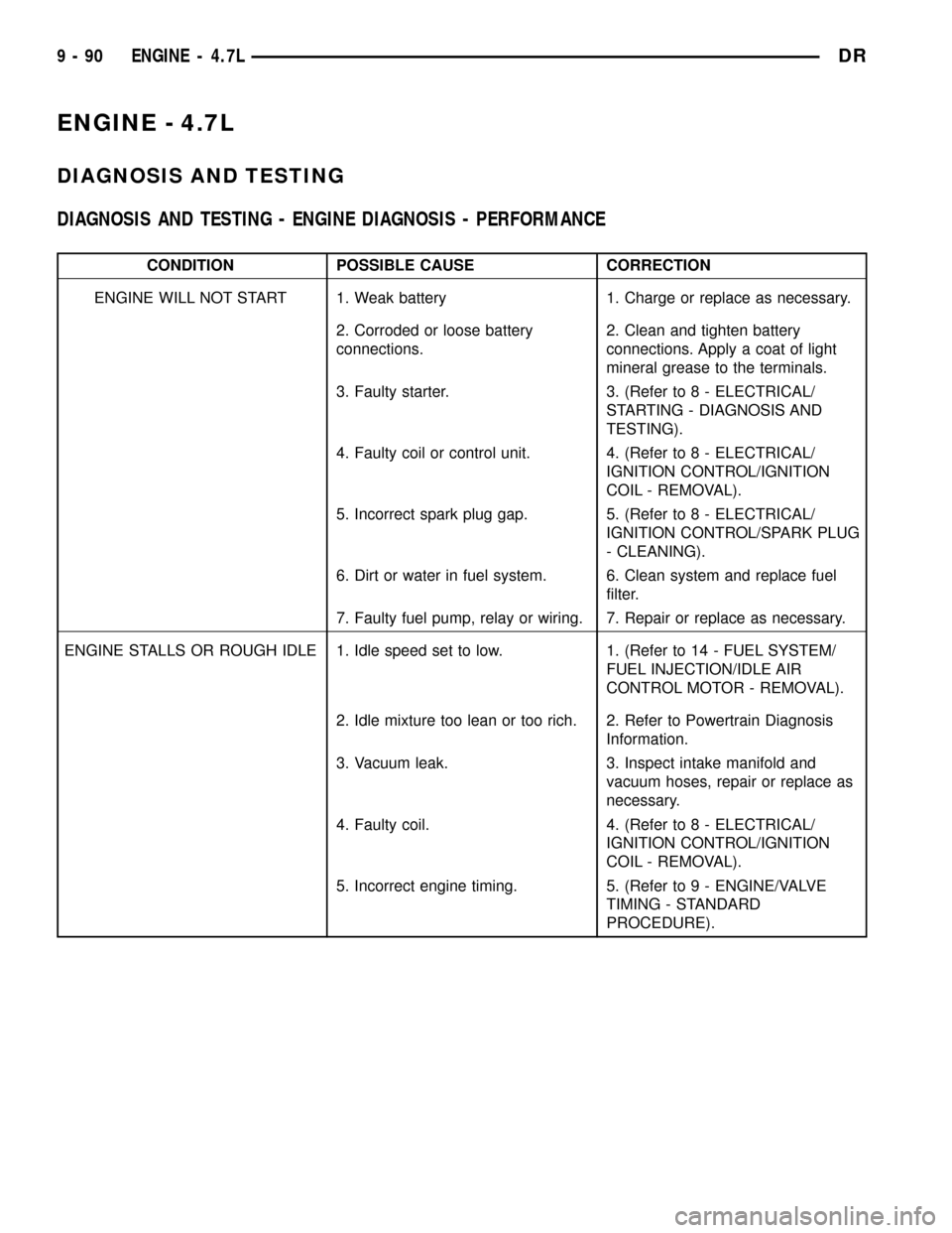
ENGINE - 4.7L
DIAGNOSIS AND TESTING
DIAGNOSIS AND TESTING - ENGINE DIAGNOSIS - PERFORMANCE
CONDITION POSSIBLE CAUSE CORRECTION
ENGINE WILL NOT START 1. Weak battery 1. Charge or replace as necessary.
2. Corroded or loose battery
connections.2. Clean and tighten battery
connections. Apply a coat of light
mineral grease to the terminals.
3. Faulty starter. 3. (Refer to 8 - ELECTRICAL/
STARTING - DIAGNOSIS AND
TESTING).
4. Faulty coil or control unit. 4. (Refer to 8 - ELECTRICAL/
IGNITION CONTROL/IGNITION
COIL - REMOVAL).
5. Incorrect spark plug gap. 5. (Refer to 8 - ELECTRICAL/
IGNITION CONTROL/SPARK PLUG
- CLEANING).
6. Dirt or water in fuel system. 6. Clean system and replace fuel
filter.
7. Faulty fuel pump, relay or wiring. 7. Repair or replace as necessary.
ENGINE STALLS OR ROUGH IDLE 1. Idle speed set to low. 1. (Refer to 14 - FUEL SYSTEM/
FUEL INJECTION/IDLE AIR
CONTROL MOTOR - REMOVAL).
2. Idle mixture too lean or too rich. 2. Refer to Powertrain Diagnosis
Information.
3. Vacuum leak. 3. Inspect intake manifold and
vacuum hoses, repair or replace as
necessary.
4. Faulty coil. 4. (Refer to 8 - ELECTRICAL/
IGNITION CONTROL/IGNITION
COIL - REMOVAL).
5. Incorrect engine timing. 5. (Refer to 9 - ENGINE/VALVE
TIMING - STANDARD
PROCEDURE).
9 - 90 ENGINE - 4.7LDR
Page 1321 of 2627

Position both the left and right side engine mount
brackets and install the through bolts and nuts.
Tighten nuts to4X2 vehicles95 N´m (70 ft. lbs.).
4X4 vehicles102 N´m (75 ft. lbs.).
(2)4X4 vehiclesInstall locknuts onto the engine
mount brackets. Tighten locknuts to 41 N´m (30 ft.
lbs.).
(3) Remove jack from under the transmission.
(4) Remove Engine Lifting Fixture Special Tool
8347 (Fig. 4).
(5) Remove Special Tools 8400 Lifting Studs.
(6) Position generator wiring behind the oil dip-
stick tube, then install the oil dipstick tube upper
mounting bolt.
(7) Connect both left and right side body ground
straps.
(8) Install power steering pump.
(9) Connect fuel supply line quick connect fitting
(Refer to 14 - FUEL SYSTEM/FUEL DELIVERY/
QUICK CONNECT FITTING - STANDARD PROCE-
DURE).
(10) Connect the vacuum lines at the throttle body
and intake manifold.
(11) Connect engine harness at the following
points (Fig. 3):
²Intake Air Temperature (IAT) Sensor
²Idle Air Control (IAC) Motor
²Fuel Injectors
²Throttle Position (TPS) Switch
²Engine Oil Pressure Switch
²Engine Coolant Temperature (ECT) Sensor
²Manifold Absolute Pressure (MAP) Sensor
²Camshaft Position (CMP) Sensor
²Coil Over Plugs
(12) Position and install heater hoses and tubes
onto intake manifold.
(13) Install the heater hoses onto the heater core
and the engine front cover.
(14) Install generator (Refer to 8 - ELECTRICAL/
CHARGING/GENERATOR - INSTALLATION).
(15) Install A/C condenser (Refer to 24 - HEATING
& AIR CONDITIONING/PLUMBING/A/C CON-
DENSER - INSTALLATION), radiator (Refer to 7 -
COOLING/ENGINE/RADIATOR - INSTALLATION)
and transmission oil cooler.
(16) Connect radiator upper and lower hoses.
(17) Connect the transmission oil cooler lines to
the radiator.
(18) Install accessory drive belt (Refer to 7 -
COOLING/ACCESSORY DRIVE/DRIVE BELTS -INSTALLATION), fan assembly and shroud (Refer to
7 - COOLING/ENGINE/FAN DRIVE VISCOUS
CLUTCH - INSTALLATION).
(19) Install A/C compressor (Refer to 24 - HEAT-
ING & AIR CONDITIONING/PLUMBING/A/C COM-
PRESSOR - INSTALLATION).
(20) Install both breathers. Connect tube to both
crankcase breathers (Fig. 2).
(21) Connect throttle and speed control cables.
(22) Install throttle body resonator assembly and
air inlet hose. Tighten clamps 4 N´m (35 in. lbs.).
(23) Raise vehicle.
(24) Install transmission to engine mounting bolts.
Tighten the bolts to 41 N´m (30 ft. lbs.).
(25) Install torque converter bolts (Automatic
Transmission Only).
(26) Connect crankshaft position sensor (Fig. 1).
(27)4X4 vehiclesPosition and install the axle
isolator bracket onto the axle, transmission and
engine block. Tighten bolts to specification (Refer to 9
- ENGINE - SPECIFICATIONS).
(28) Install starter (Refer to 8 - ELECTRICAL/
STARTING/STARTER MOTOR - INSTALLATION).
CAUTION: The structural cover requires a specific
torque sequence. Failure to follow this sequence
may cause severe damage to the cover.
(29) Install structural cover (Refer to 9 - ENGINE/
ENGINE BLOCK/STRUCTURAL COVER - INSTAL-
LATION).
(30) Install exhaust crossover pipe.
(31) Install engine block heater power cable, If
equipped.
(32)4X4 vehiclesConnect axle vent tube to left
side engine mount.
(33) Lower vehicle.
(34) Check and fill engine oil.
(35) Recharge the A/C system (Refer to 24 - HEAT-
ING & AIR CONDITIONING/PLUMBING/REFRIG-
ERANT - STANDARD PROCEDURE).
(36) Refill the engine cooling system (Refer to 7 -
COOLING - STANDARD PROCEDURE).
(37) Install the battery tray and battery.
(38) Connect the battery positive and negative
cables.
(39) Start the engine and check for leaks.
9 - 98 ENGINE - 4.7LDR
ENGINE - 4.7L (Continued)