1998 DODGE RAM 1500 Fuel injector
[x] Cancel search: Fuel injectorPage 1629 of 2627
INSTALLATION
All high-pressure fuel lines are of the same length
and inside diameter. Correct high-pressure fuel line
usage and installation is critical to smooth engine
operation.
CAUTION: Anytime a high-pressure line is removed
from the engine, its fuel connector nut at the cylin-
der head must first be retorqued. Refer to Torque
Specifications.
(1) Tighten fuel lines at high pressure injector con-
nector. Refer to Torque Specifications.
(2) Position fuel line support clamp(s) to fuel
line(s). Install clamp nuts/bolts and tighten finger
tight.
(3) Position proper fuel line to proper injector on
engine. Tighten fittings hand tight at both ends of
line.
(4) Tighten fuel lines at fuel rail. Refer to Torque
Specifications.
(5) Tighten clamp/support nuts and bolts. Refer to
Torque Specifications.
(6) Install engine lifting bracket and bolt. Refer to
Torque Specifications.
(7) If fuel line at either #1 or #2 cylinder has been
replaced, install intake manifold air heater elements
to top of intake manifold. Refer to Intake Air Heater
Removal / Installation for procedures.
(8) If fuel line at #6 cylinder has been replaced, tilt
metal bracket upward and tighten 2 bolts at rear of
cylinder head. Refer to Torque Specifications.
(9) Install remaining fuel line support clamps and
bracket bolts at intake manifold. Refer to Torque
Specifications.
(10) Connect both negative battery cables to both
batteries.
(11) Prime fuel system. Refer to Fuel System
Priming.
(12) Check lines/fittings for leaks.
FUEL PRESSURE SENSOR
DESCRIPTION
The fuel pressure sensor is mounted vertically near
the top/center of the fuel rail.
OPERATION
The fuel pressure sensor monitors actual high-
pressure within the fuel rail. An output signal from
this sensor (relating to fuel pressure) is sent to the
Engine Control Module (ECM).
REMOVAL
The fuel pressure sensor is mounted vertically near
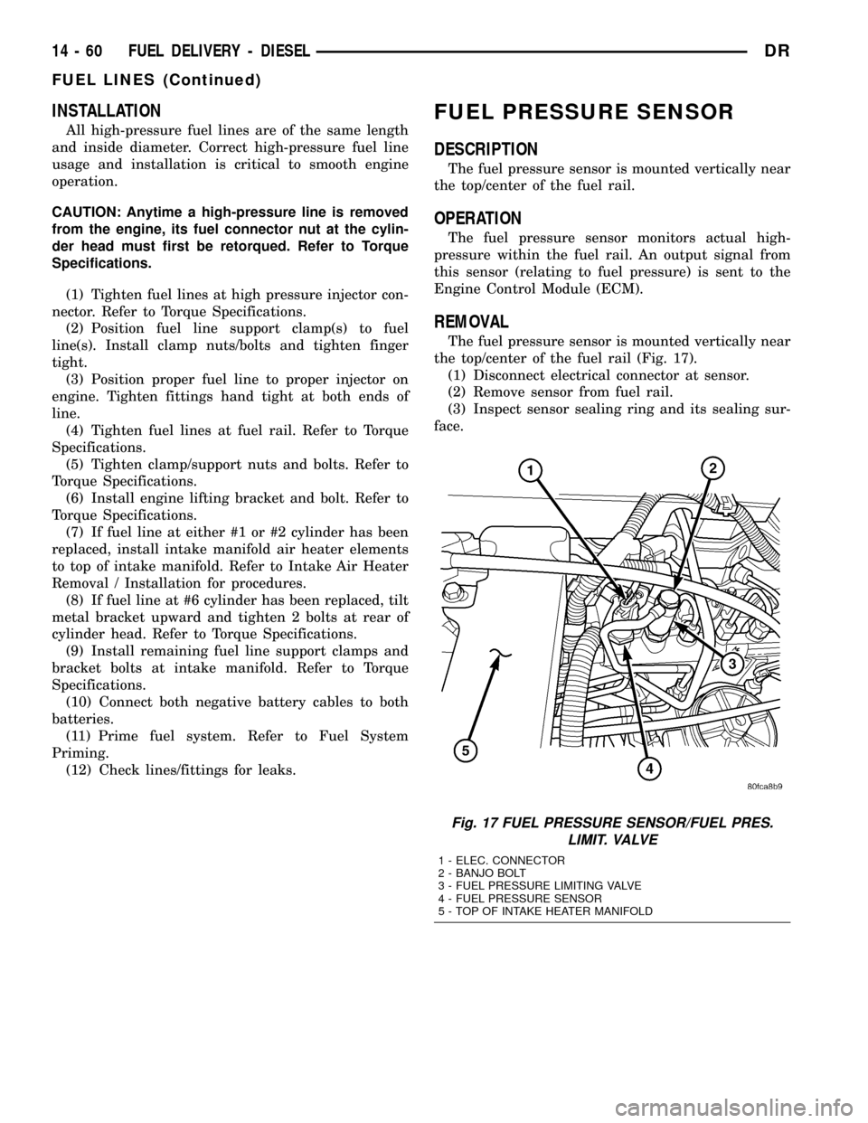
the top/center of the fuel rail (Fig. 17).
(1) Disconnect electrical connector at sensor.
(2) Remove sensor from fuel rail.
(3) Inspect sensor sealing ring and its sealing sur-
face.
Fig. 17 FUEL PRESSURE SENSOR/FUEL PRES.
LIMIT. VALVE
1 - ELEC. CONNECTOR
2 - BANJO BOLT
3 - FUEL PRESSURE LIMITING VALVE
4 - FUEL PRESSURE SENSOR
5 - TOP OF INTAKE HEATER MANIFOLD
14 - 60 FUEL DELIVERY - DIESELDR
FUEL LINES (Continued)
Page 1630 of 2627
INSTALLATION
(1) Inspect fuel pressure sensor sealing surface.
(2) Lubricate sensor threads with clean diesel fuel.
(3) Install sensor into fuel rail.
(4) To prevent leaks, sensormustbe tightened to
prescribed torque. Refer to Torque Specifications.
(5) Connect electrical connector to sensor.
(6) Start engine and check for fuel leaks.
FUEL PRESSURE LIMITING
VA LV E
DESCRIPTION
The fuel pressure limiting valve is located on the
top of the fuel rail.
OPERATION
Fuel pressure at the fuel rail is monitored by the
fuel rail pressure sensor. If fuel pressure becomes
excessive, the pressure limiting valve opens and
vents excess pressure into the fuel drain circuit.
REMOVAL
The fuel pressure limiting valve is located on the
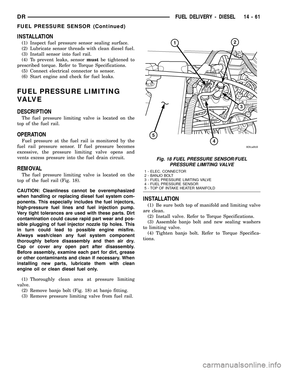
top of the fuel rail (Fig. 18).
CAUTION: Cleanliness cannot be overemphasized
when handling or replacing diesel fuel system com-
ponents. This especially includes the fuel injectors,
high-pressure fuel lines and fuel injection pump.
Very tight tolerances are used with these parts. Dirt
contamination could cause rapid part wear and pos-
sible plugging of fuel injector nozzle tip holes. This
in turn could lead to possible engine misfire.
Always wash/clean any fuel system component
thoroughly before disassembly and then air dry.
Cap or cover any open part after disassembly.
Before assembly, examine each part for dirt, grease
or other contaminants and clean if necessary. When
installing new parts, lubricate them with clean
engine oil or clean diesel fuel only.
(1) Thoroughly clean area at pressure limiting
valve.
(2) Remove banjo bolt (Fig. 18) at banjo fitting.
(3) Remove pressure limiting valve from fuel rail.
INSTALLATION
(1) Be sure both top of manifold and limiting valve
are clean.
(2) Install valve. Refer to Torque Specifications.
(3) Assemble banjo bolt and new sealing washers
to limiting valve.
(4) Tighten banjo bolt. Refer to Torque Specifica-
tions.
Fig. 18 FUEL PRESSURE SENSOR/FUEL
PRESSURE LIMITING VALVE
1 - ELEC. CONNECTOR
2 - BANJO BOLT
3 - FUEL PRESSURE LIMITING VALVE
4 - FUEL PRESSURE SENSOR
5 - TOP OF INTAKE HEATER MANIFOLD
DRFUEL DELIVERY - DIESEL 14 - 61
FUEL PRESSURE SENSOR (Continued)
Page 1633 of 2627
INSTALLATION
CAUTION: Whenever the fuel tank module is ser-
viced, the rubber gasket must be replaced.
(1) Thoroughly clean locknut and locknut threads
at top of tank.(2) Using new gasket, carefully position fuel tank
module into opening in fuel tank.
(3) Position locknut over top of fuel tank module.
Install locknut finger tight.
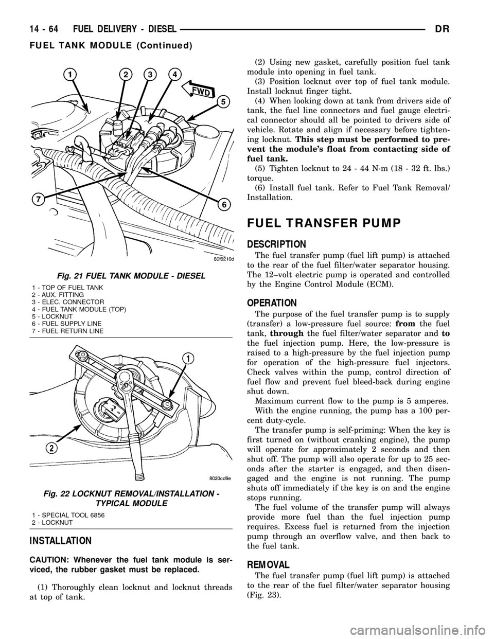
(4) When looking down at tank from drivers side of
tank, the fuel line connectors and fuel gauge electri-
cal connector should all be pointed to drivers side of
vehicle. Rotate and align if necessary before tighten-
ing locknut.This step must be performed to pre-
vent the module's float from contacting side of
fuel tank.
(5) Tighten locknut to 24 - 44 N´m (18 - 32 ft. lbs.)
torque.
(6) Install fuel tank. Refer to Fuel Tank Removal/
Installation.
FUEL TRANSFER PUMP
DESCRIPTION
The fuel transfer pump (fuel lift pump) is attached
to the rear of the fuel filter/water separator housing.
The 12±volt electric pump is operated and controlled
by the Engine Control Module (ECM).
OPERATION
The purpose of the fuel transfer pump is to supply
(transfer) a low-pressure fuel source:fromthe fuel
tank,throughthe fuel filter/water separator andto
the fuel injection pump. Here, the low-pressure is
raised to a high-pressure by the fuel injection pump
for operation of the high-pressure fuel injectors.
Check valves within the pump, control direction of
fuel flow and prevent fuel bleed-back during engine
shut down.
Maximum current flow to the pump is 5 amperes.
With the engine running, the pump has a 100 per-
cent duty-cycle.
The transfer pump is self-priming: When the key is
first turned on (without cranking engine), the pump
will operate for approximately 2 seconds and then
shut off. The pump will also operate for up to 25 sec-
onds after the starter is engaged, and then disen-
gaged and the engine is not running. The pump
shuts off immediately if the key is on and the engine
stops running.
The fuel volume of the transfer pump will always
provide more fuel than the fuel injection pump
requires. Excess fuel is returned from the injection
pump through an overflow valve, and then back to
the fuel tank.
REMOVAL
The fuel transfer pump (fuel lift pump) is attached
to the rear of the fuel filter/water separator housing
(Fig. 23).
Fig. 21 FUEL TANK MODULE - DIESEL
1 - TOP OF FUEL TANK
2 - AUX. FITTING
3 - ELEC. CONNECTOR
4 - FUEL TANK MODULE (TOP)
5 - LOCKNUT
6 - FUEL SUPPLY LINE
7 - FUEL RETURN LINE
Fig. 22 LOCKNUT REMOVAL/INSTALLATION -
TYPICAL MODULE
1 - SPECIAL TOOL 6856
2 - LOCKNUT
14 - 64 FUEL DELIVERY - DIESELDR
FUEL TANK MODULE (Continued)
Page 1636 of 2627
FUEL DRAIN CIRCUIT
OPERATION
The Fuel Drain Circuit incorporates several
sources of fuel return. Fuel travels from the fuel tank
to the fuel transfer pump and is forced through the
fuel filter. This fuel then travels into the fuel injec-
tion pump. It then goes to a fuel drain line and
returns back to the fuel tank.
The fuel that flows to the fuel pump is pressurized
by a gear pump and internally transferred to the fuel
injection pump. At this point the fuel is channeled
into two passages. One passage sends fuel to the
FCA (Fuel Control Actuator). The other passage
sends fuel to the cascade overflow valve. The over-
flow valve sends some fuel to a lubrication passage.
The rest of the fuel is sent to a drain passage which
connects to an external fuel line.Fuel that travels through the FCA is pressurized
by the fuel injection pump and sent through an
external high pressure fuel line to the fuel rail. At
the fuel rail, fuel is sent to the fuel injectors. If fuel
pressure in the fuel rail becomes excessive, the pres-
sure limiting valve opens and sends fuel through an
external fuel line.
At the fuel injector, fuel that is not injected is used
for lubrication of the fuel injectors. This fuel then
travels through an internal passage that is connected
to the rear of the cylinder head, an then into an
external fuel line. This line is connected to the vehi-
cles fuel return line, and returns excess fuel to the
fuel tank.
DRFUEL DELIVERY - DIESEL 14 - 67
Page 1637 of 2627
FUEL INJECTION - DIESEL
TABLE OF CONTENTS
page page
ACCELERATOR PEDAL POSITION SENSOR
DESCRIPTION.........................68
OPERATION...........................68
REMOVAL.............................68
INSTALLATION.........................71
CAMSHAFT POSITION SENSOR
DESCRIPTION.........................71
OPERATION...........................71
REMOVAL.............................72
INSTALLATION.........................72
CRANKSHAFT POSITION SENSOR
DESCRIPTION.........................72
OPERATION...........................72
REMOVAL.............................73
INSTALLATION.........................73
FUEL CONTROL ACTUATOR
DESCRIPTION.........................74
OPERATION...........................74
REMOVAL.............................74
FUEL INJECTOR
DESCRIPTION.........................74
OPERATION...........................74
REMOVAL.............................75
INSTALLATION.........................77
FUEL INJECTOR RAIL
DESCRIPTION.........................78
OPERATION...........................78
REMOVAL.............................78
INSTALLATION.........................78INLET AIR TEMPERATURE SENSOR/
PRESSURE SENSOR
DESCRIPTION.........................79
OPERATION...........................79
REMOVAL.............................79
INSTALLATION.........................79
INTAKE AIR HEATER
DESCRIPTION.........................80
OPERATION...........................80
REMOVAL.............................80
INSTALLATION.........................80
INTAKE AIR HEATER RELAY
DESCRIPTION.........................82
OPERATION...........................82
REMOVAL.............................82
INSTALLATION.........................82
INTAKE AIR TEMPERATURE SENSOR/MAP
SENSOR
DESCRIPTION.........................82
OPERATION...........................82
REMOVAL.............................82
INSTALLATION.........................82
MAP SENSOR
DESCRIPTION.........................83
THROTTLE CONTROL CABLE
REMOVAL.............................83
INSTALLATION.........................84
PTO SWITCH
DESCRIPTION.........................85
OPERATION...........................85
ACCELERATOR PEDAL
POSITION SENSOR
DESCRIPTION
Engine Mounted Sensor:The APPS assembly is
located at the top-left-front of the engine. A plastic
cover is used to cover the assembly. The actual sen-
sor is located behind its mounting bracket.
Battery Tray Mounted Sensor:The Accelerator
Pedal Position Sensor (APPS) assembly is located
under the vehicle battery tray. A cable connects the
assembly to the accelerator pedal. A plastic cover
with a movable door is used to cover the assembly.
OPERATION
Engine Mounted Sensor:The Accelerator Pedal
Position Sensor (APPS) is a linear potentiometer. Itprovides the Engine Control Module (ECM) with a
DC voltage signal proportional to the angle, or posi-
tion of the accelerator pedal.
Battery Tray Mounted Sensor:The APPS pro-
vides the ECM with two DC voltage signals which
change as the position of the accelerator changes.
One of the DC voltage signals will be half the voltage
of the other signal.
REMOVAL
Engine Mounted Sensor :
The APPS is serviced (replaced) as one assembly
including the lever, brackets and sensor. The APPS is
calibrated to its mounting bracket. The APPS assem-
bly is located at left-front of engine below plastic
cable/lever/linkage cover (Fig. 1).
14 - 68 FUEL INJECTION - DIESELDR
Page 1643 of 2627
FUEL CONTROL ACTUATOR
DESCRIPTION
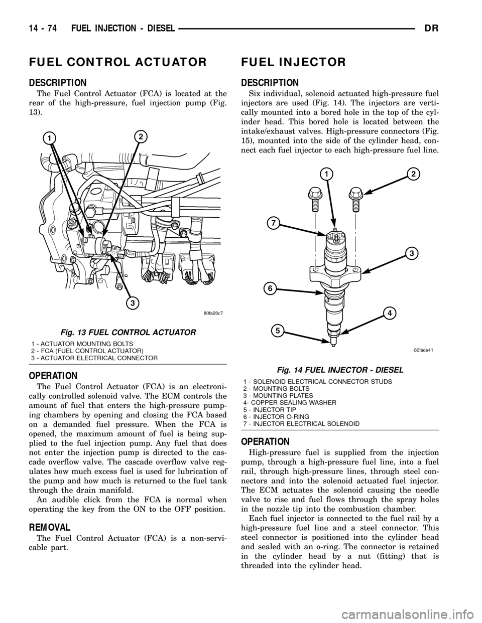
The Fuel Control Actuator (FCA) is located at the
rear of the high-pressure, fuel injection pump (Fig.
13).
OPERATION
The Fuel Control Actuator (FCA) is an electroni-
cally controlled solenoid valve. The ECM controls the
amount of fuel that enters the high-pressure pump-
ing chambers by opening and closing the FCA based
on a demanded fuel pressure. When the FCA is
opened, the maximum amount of fuel is being sup-
plied to the fuel injection pump. Any fuel that does
not enter the injection pump is directed to the cas-
cade overflow valve. The cascade overflow valve reg-
ulates how much excess fuel is used for lubrication of
the pump and how much is returned to the fuel tank
through the drain manifold.
An audible click from the FCA is normal when
operating the key from the ON to the OFF position.
REMOVAL
The Fuel Control Actuator (FCA) is a non-servi-
cable part.
FUEL INJECTOR
DESCRIPTION
Six individual, solenoid actuated high-pressure fuel
injectors are used (Fig. 14). The injectors are verti-
cally mounted into a bored hole in the top of the cyl-
inder head. This bored hole is located between the
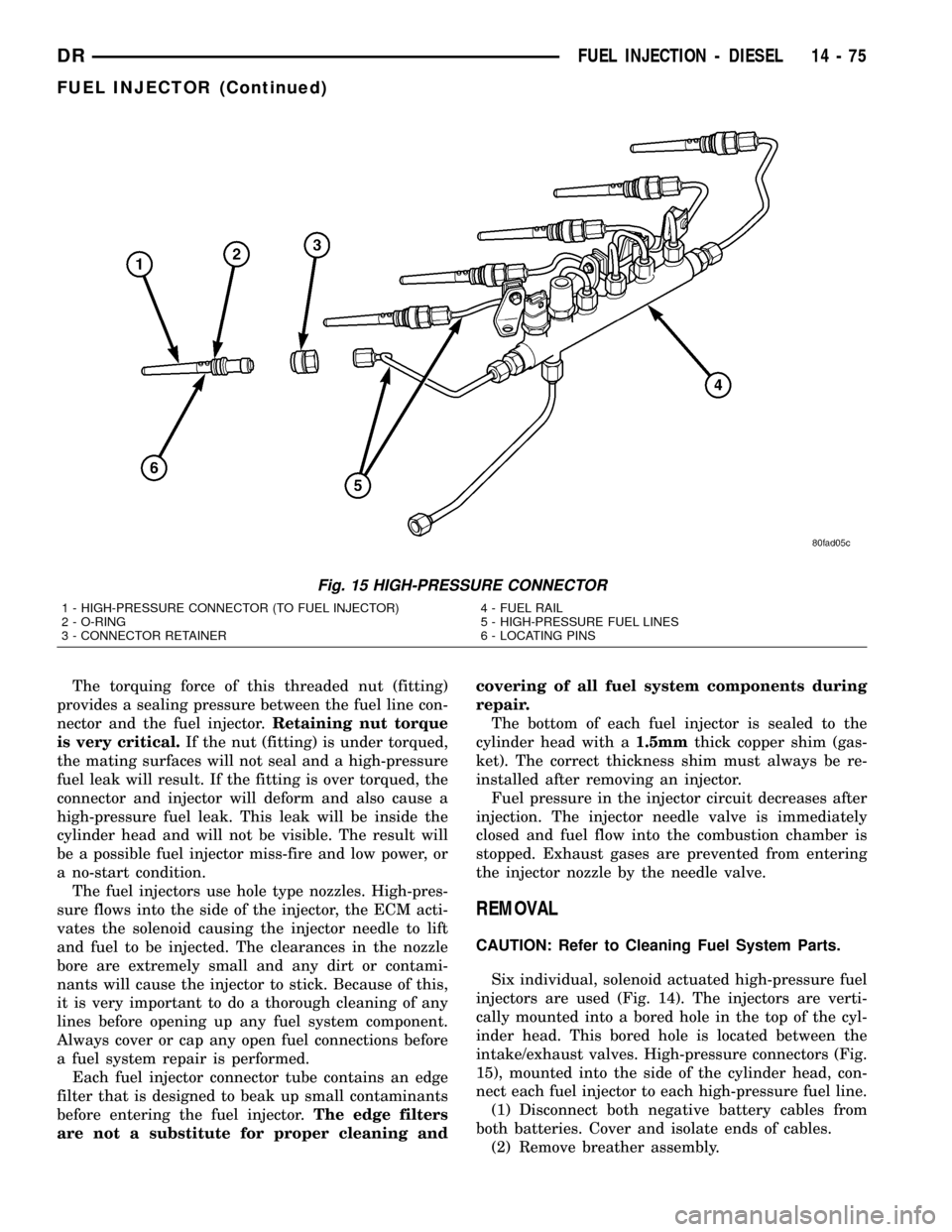
intake/exhaust valves. High-pressure connectors (Fig.
15), mounted into the side of the cylinder head, con-
nect each fuel injector to each high-pressure fuel line.
OPERATION
High-pressure fuel is supplied from the injection
pump, through a high-pressure fuel line, into a fuel
rail, through high-pressure lines, through steel con-
nectors and into the solenoid actuated fuel injector.
The ECM actuates the solenoid causing the needle
valve to rise and fuel flows through the spray holes
in the nozzle tip into the combustion chamber.
Each fuel injector is connected to the fuel rail by a
high-pressure fuel line and a steel connector. This
steel connector is positioned into the cylinder head
and sealed with an o-ring. The connector is retained
in the cylinder head by a nut (fitting) that is
threaded into the cylinder head.
Fig. 13 FUEL CONTROL ACTUATOR
1 - ACTUATOR MOUNTING BOLTS
2 - FCA (FUEL CONTROL ACTUATOR)
3 - ACTUATOR ELECTRICAL CONNECTOR
Fig. 14 FUEL INJECTOR - DIESEL
1 - SOLENOID ELECTRICAL CONNECTOR STUDS
2 - MOUNTING BOLTS
3 - MOUNTING PLATES
4- COPPER SEALING WASHER
5 - INJECTOR TIP
6 - INJECTOR O-RING
7 - INJECTOR ELECTRICAL SOLENOID
14 - 74 FUEL INJECTION - DIESELDR
Page 1644 of 2627
The torquing force of this threaded nut (fitting)
provides a sealing pressure between the fuel line con-
nector and the fuel injector.Retaining nut torque
is very critical.If the nut (fitting) is under torqued,
the mating surfaces will not seal and a high-pressure
fuel leak will result. If the fitting is over torqued, the
connector and injector will deform and also cause a
high-pressure fuel leak. This leak will be inside the
cylinder head and will not be visible. The result will
be a possible fuel injector miss-fire and low power, or
a no-start condition.
The fuel injectors use hole type nozzles. High-pres-
sure flows into the side of the injector, the ECM acti-
vates the solenoid causing the injector needle to lift
and fuel to be injected. The clearances in the nozzle
bore are extremely small and any dirt or contami-
nants will cause the injector to stick. Because of this,
it is very important to do a thorough cleaning of any
lines before opening up any fuel system component.
Always cover or cap any open fuel connections before
a fuel system repair is performed.
Each fuel injector connector tube contains an edge
filter that is designed to beak up small contaminants
before entering the fuel injector.The edge filters
are not a substitute for proper cleaning andcovering of all fuel system components during
repair.
The bottom of each fuel injector is sealed to the
cylinder head with a1.5mmthick copper shim (gas-
ket). The correct thickness shim must always be re-
installed after removing an injector.
Fuel pressure in the injector circuit decreases after
injection. The injector needle valve is immediately
closed and fuel flow into the combustion chamber is
stopped. Exhaust gases are prevented from entering
the injector nozzle by the needle valve.
REMOVAL
CAUTION: Refer to Cleaning Fuel System Parts.
Six individual, solenoid actuated high-pressure fuel
injectors are used (Fig. 14). The injectors are verti-
cally mounted into a bored hole in the top of the cyl-
inder head. This bored hole is located between the
intake/exhaust valves. High-pressure connectors (Fig.
15), mounted into the side of the cylinder head, con-
nect each fuel injector to each high-pressure fuel line.
(1) Disconnect both negative battery cables from
both batteries. Cover and isolate ends of cables.
(2) Remove breather assembly.
Fig. 15 HIGH-PRESSURE CONNECTOR
1 - HIGH-PRESSURE CONNECTOR (TO FUEL INJECTOR)
2 - O-RING
3 - CONNECTOR RETAINER4 - FUEL RAIL
5 - HIGH-PRESSURE FUEL LINES
6 - LOCATING PINS
DRFUEL INJECTION - DIESEL 14 - 75
FUEL INJECTOR (Continued)
Page 1645 of 2627
(3) Remove valve cover. Refer to Engines for proce-
dures.
(4) Remove necessary high pressure fuel line con-
necting necessary fuel injector rail to high pressure
connector. Refer to Fuel Line Removal for procedures.
(5) A connector retainer (nut) (Fig. 15) is used on
each connector tube. Remove this nut(s) by unthread-
ing from cylinder head.
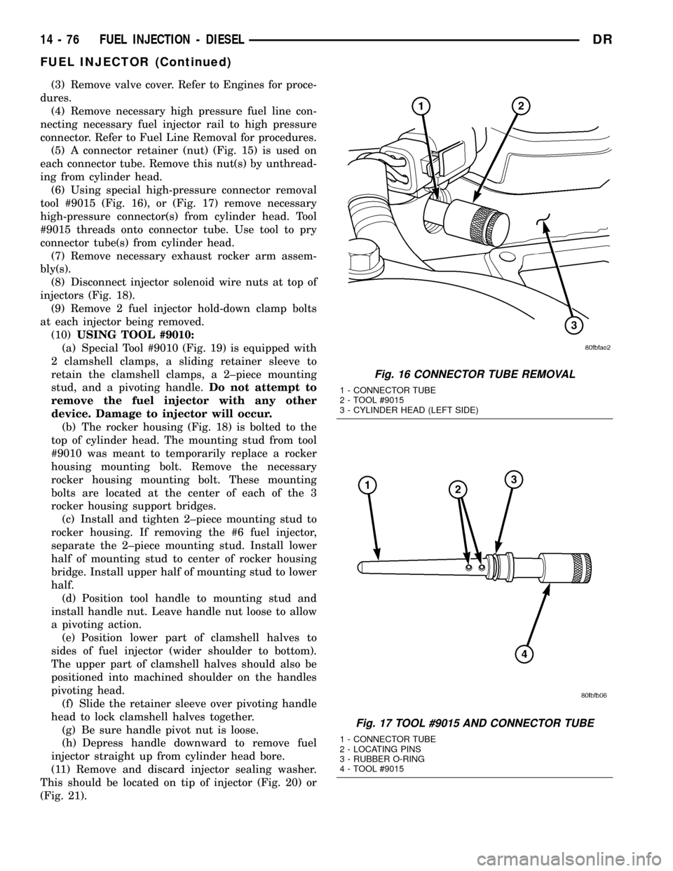
(6) Using special high-pressure connector removal
tool #9015 (Fig. 16), or (Fig. 17) remove necessary
high-pressure connector(s) from cylinder head. Tool
#9015 threads onto connector tube. Use tool to pry
connector tube(s) from cylinder head.
(7) Remove necessary exhaust rocker arm assem-
bly(s).
(8) Disconnect injector solenoid wire nuts at top of
injectors (Fig. 18).
(9) Remove 2 fuel injector hold-down clamp bolts
at each injector being removed.
(10)USING TOOL #9010:
(a) Special Tool #9010 (Fig. 19) is equipped with
2 clamshell clamps, a sliding retainer sleeve to
retain the clamshell clamps, a 2±piece mounting
stud, and a pivoting handle.Do not attempt to
remove the fuel injector with any other
device. Damage to injector will occur.
(b) The rocker housing (Fig. 18) is bolted to the
top of cylinder head. The mounting stud from tool
#9010 was meant to temporarily replace a rocker
housing mounting bolt. Remove the necessary
rocker housing mounting bolt. These mounting
bolts are located at the center of each of the 3
rocker housing support bridges.
(c) Install and tighten 2±piece mounting stud to
rocker housing. If removing the #6 fuel injector,
separate the 2±piece mounting stud. Install lower
half of mounting stud to center of rocker housing
bridge. Install upper half of mounting stud to lower
half.
(d) Position tool handle to mounting stud and
install handle nut. Leave handle nut loose to allow
a pivoting action.
(e) Position lower part of clamshell halves to
sides of fuel injector (wider shoulder to bottom).
The upper part of clamshell halves should also be
positioned into machined shoulder on the handles
pivoting head.
(f) Slide the retainer sleeve over pivoting handle
head to lock clamshell halves together.
(g) Be sure handle pivot nut is loose.
(h) Depress handle downward to remove fuel
injector straight up from cylinder head bore.
(11) Remove and discard injector sealing washer.
This should be located on tip of injector (Fig. 20) or
(Fig. 21).
Fig. 16 CONNECTOR TUBE REMOVAL
1 - CONNECTOR TUBE
2 - TOOL #9015
3 - CYLINDER HEAD (LEFT SIDE)
Fig. 17 TOOL #9015 AND CONNECTOR TUBE
1 - CONNECTOR TUBE
2 - LOCATING PINS
3 - RUBBER O-RING
4 - TOOL #9015
14 - 76 FUEL INJECTION - DIESELDR
FUEL INJECTOR (Continued)