Page 17 of 36
Convertible Tops - 17
EM TOP EMERGENCY OPERATION
In the event of electrical failure, the top can be raised manually. The procedure is as fol-
lows:
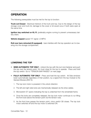
Pull the release lever located under the left rear
seat cushion as shown.
Both motors are disconnected from the gear
drives.
The top storage cover is unlocked.
NOTE:The top can not be lowered again until electrical power is restored to the system.
This is due to the fact that the top storage cover can not be locked until power is restored.
Page 18 of 36
RE-CONNECTING DRIVE MOTORS
Due to the interlock of the trunk lid an unlocked top storage cover, the following procedure
must be followed to reconnect the top drive motors, to restore electrical operation:
•Lower all the side windows with the central switch
•Unlock the top from the windshield frame, raise it over the tension point and open the
storage cover.
•Lower the top into the storage compartment and close the storage cover.
•Disconnect fuse #7 in the front power distribution box (this will override the forced lock-
ing of the trunk).
•Open the trunk lid and remove the trim cover from the left side of the trunk.
•Reconnect the motors with the gear drives. The actuating rods can be moved slightly
to allow the gear teeth to engage.
•Close trunk lid and reinstall fuse #7.
•The EM top system must now be initialized to restore normal operation.
Convertible Tops - 18
Page 19 of 36

Convertible Tops - 19
EM TOP INITIALIZATION
Initialization of the system is required for the CVM to learn the end limits of the top storage
cover. The CVM counts the pulses from the integrated hall sensor in the cover motor to
determine the cover position.
An initialization run occurs automatically after every eighth operation of the top. This
ensures that the hall sensor counting circuit is not adversely affected by any backlash or
elasticity of the top cover drive mechanism.
The hall sensor counter reading is
stored in a NV RAM, however it is
possible for this data to be incor-
rect or out of sync for the following
conditions:
Power supply interrupted while
top is in operation
Electrical failures that require
manual closing of the top.
Follow the procedures on this page
or refer to Group 54 in the Repair
Manual of TIS.
INITIALIZATION PROCEDURE
1. The top must be placed in the storage compartment
Motors engaged with the drives.
Top storage cover closed
2. Ignition key switched OFF.
3. Press and hold the top switch in the lowering direction.
4. Switch the ignition on (KL R).
5. After approximately 10 seconds the top storage cover will start to close and lock.
6. At this point release the the top switch. The initialization procedure will continue run-
ning. The procedure is complete approximately 0.5 seconds after the top storage cover
is closed and locked.
NOTE: The initialization procedure can be interrupted by switching the ignition off.
Page 20 of 36

Convertible Tops - 20
CONTROL MODULE DIAGNOSIS/TROUBLESHOOTING
Faults that occur during opera-
tion of the top are stored in the
CVM.
They are accessed with the DIS
Tester or MoDiC.
The table reflects the possible
fault codes stored in the CVM.
Additionally, the diagnostic
requests (status) and compo-
nent activation function pro-
vides quick diagnostic checks
of signal status and output
function of components.
Always verify the control mod-
ule identification against the
tester display screen when
testing or troubleshooting the
EM top system.
Always check any associated
or inter-connected systems
when troubleshooting EM top
problems. (ie: ZKE IV).
Check the coding data to
make sure the control module
is coded correctly for the spe-
cific top system in the vehicle.
Always use the latest software
available to test and trou-
bleshoot the system.Fault Code Description
1 Short to ground motor
2 Short to B+ motor
3 Position not plausible
4 Distance/time measurement of the
convertible top
5 Fault “rollover sensor”
6 Internal fault of the module
7 Current through CVM too great
Page 21 of 36
Page 22 of 36
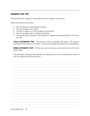
CONVERTIBLE TOP STORAGE LID POSITION HALL SENSOR TESTS
Before testing always verify pin numbers and
wire colors from the appropriate ETM.
DC Voltage Test Procedures:
•At X13145 disconnect and access ground
(pin 6) and the hall sensor supply voltage
(pin 3) = battery voltage.
•Re-connect plug and check hall sensor sig-
nal (pin 2), activate convertible top, with
storage lid in motion = 5.0 volts.
Tap switch to display high/low signal - High = 10.0 volts.
Low = 0 volts.
Voltage Frequency Test Procedure:
•With storage compartment lid moving in either direction, pin 2 = 70 Hz.
Convertible Tops - 22
v
v
mV
mA
mA
v
ACOM
FLUKE 87
FLUKE 87
FLUKE 87
Hz
Page 23 of 36
Convertible Tops - 23
E36 CONVERTIBLE TOP ADJUSTMENTS
NOTE: All mechanical adjustments are critical for synchronous top operation.
The following adjustments are possible on E36 convertibles. The Repair Manual section of
TIS provides system component R&R and adjustment procedures.
The following Repair Manual
screens are from Groups 51 & 54.
The individual listings provide all of
the pertinent procedures for effec-
tively repairing a defect and adjust-
ing the components to effectively
maintain the precision operation of
the top mechanisms.
Example:Adjusting left or right
soft top compartment cover lock.
Group 5125.. additionally includes
the following E36 convertible top
specific procedures:
•Configuration of convertible top
cover
•Replace actuating lever
•R&R Bowden Cables
•R&R Top Cover Lock
•R&R Gas Struts for Top Cover
Page 24 of 36
Convertible Tops - 24
Group 54 25.. includes the fol-
lowing:
•Adjusting both top lid locks.
•Adjusting electric motor for
convertible top lid.
•Adjusting both bowden cables
for convertible top lid locks.
Group 54 25.. additionally
includes the following E36 con-
vertible top specific procedures:
•R&R electrical convertible top
lid drive unit
•R&R both convertible top
locks.
•R&R both bowden cables for
convertible top lid locks.