1998 BMW 540i lug bolt torque
[x] Cancel search: lug bolt torquePage 513 of 1002

Downloaded from www.Manualslib.com manuals search engine
Radiator and Cooling systeml
Tightening torques
Block drain plug to block 25 Nm
(18
it-lb)
Coolant hose clamp (32 - 48 2.
5 Nm (22 in-lb)
mm hose diameter)
Radiator drain plug to radiator
2-3Nm(l8-27in-lb)
Thermostat housing to cylinder
head 10 Nm (89 in-lb)
I Coolant thermostat housing assmbly- - I
Thermostat, removing and installing
(M52 TU or M54 engine)
4 The electric map-controlled thermostat is part of the thermo-
stat housing at the front of the cylinder head.
1. Bolts (M6)
2 Bolt (ME)
3. Housing with thermostat
4. Gasket
- If a faulty thermostat is suspected, use appropriate scan tool
to interrogate
ECM for stored fault codes.
- Drain radiator and engine block. See Coolant, draining and
filling (6-cylinder models).
CAUTION-
Allow cooling system to cool before opening or draining the
system.
- Remove cooling fan and fan shroud. See Mechanical (vis-
cous clutch) cooling fan, removing and installing.
- Disconnect electrical harness connector from thermostat
housina.
4 Lever out retaining clips (arrows) and pull hose fittings off
thermostat housing.
- Unbolt and remove thermostat housing from front of engine.
Loosen nut at top of engine lifting eye to facilitate removal.
- Installation is reverse of removal, noting the following:
Keep sealing faces free of oil.
* Use new sealing gasket.
When reinstalling hose to thermostat housing, install clip
on hose end fitting, then push hose onto housing until it
clicks into place.
Fill system with coolant. See Coolant, draining and fill-
ing (6-cylinder models).
Page 515 of 1002

Downloaded from www.Manualslib.com manuals search engine
170-1 9
Radiator and Cooling System
Coolant pump Remove thermostat housing fasteners
(arrows) and remove
thermostat housing.
Installation is reverse of removal, noting the following:
- Keep sealing faces clean and free of oil.
Use new sealing gasket.
Fill system with coolant. See Coolant, draining and fill-
ing
(V-8 models).
Tightening torques
Block drain plug to block 25 Nm (18 it-lb)
Coolant hose clamp (32
- 48 2. 5 Nm (22 in-lb)
mm hose diameter)
Radiator drain plug to radiator 2
- 3 Nm (18 - 27 In-lb)
Thermostat cover to
coolant pump 10 Nm (89 in-lb)
Coolant pump, replacing (6-cylinder
models)
< The engine coolant pump is mounted in the front of the en-
gine in the timing chain cover.
- Drain cooling system as described earlier. See Coolant,
draining and filling (6-cylinder models).
WARNING-
Allow cooling system to cool before opening or draining sys-
tem.
- Remove cooling fan and fan shroud. See Mechanical (vis-
cous clutch) cooling fan, removing and installing.
- Remove coolant pump drive belt. See 020 Maintenance.
4 Remove coolant pump pulley bolts (arrows) and remove pul-
ley from pump.
- Remove nuts retaining pump to engine block.
NOTE-
The coolant pump is mounted on studs and retained by nuts.
Page 520 of 1002

Downloaded from www.Manualslib.com manuals search engine
--
Radiator and Cooling System 1
4 Lift fan and shroud together out of engine compartment.
- Detach upper and lower radiator hoses.
NOTE -
Later models use retaining clips to fasten coolant hoses to
expansion tank and radiator.
- Disconnect temperature sensor harness connector.
4 Remove radiator support bolts and supports (arrows). 6-cyl-
inder shown.
- Slide right side of radiator back toward engine and pull radi-
ator up to remove.
- Installation is reverse of removal, noting the following:
Fill radiator and cooling system. See Coolant, draining
and filling (6-cylinder models) or Coolant, draining
and filling (V-8 models).
Tightening torques
Engine block drain
plug to block 25 Nm (18 it-lb)
Radiator drain plug
to radiator 2 - 3 Nm (18 - 27 in-ib)
Expansion tank, removing and installing
- Raise front of car and support safely.
WARNING -
Make sure the car is stable and well supported at all times.
Use a professional automotive
/iff orjacltstands designed for
the purpose. A
floorjacl~ is not adequate support.
- Remove splash shield from under engine.
- Drain radiator as described earlier. See Coolant, draining
and filling (6-cylinder models) or Coolant, draining and
filling
(V-8 models).
I WARNING-
Allow cooling system to cool before opening or draining sys-
I tem.
Page 592 of 1002

Downloaded from www.Manualslib.com manuals search engine
Automatic Transmission
NOTE-
Use new ATF pan bolts purchased from BMW Alternatively,
clean old bolts and coat with
LoctiteB thread locl
Automatic transmission fluid capacity
with torque converter
7.8 liters (8.3 US qt)
without torque converter
3.3 liters (3.5 US qt)
A5S 360R 1 A5S 390R
with torque converter
without torque converter 9 liters (9.5 US qt)
4 liters (4.2 US qt)
A5S 3252 (2.5 liter engine)
with torque converter
without torque converter
8.9 liters (9.4 US qt)
6.2 liters (6.5 US qt)
A5S 3252 (3.0 liter engine)
with torque converter
8.7 liters (9.3 US qt)
without torque converter
6.1 liters (6.4 US qt)
A5S 5602
with torque converter 13.1 liters (13.8 US qt)
without torque converter
5.5 liters (5.8 US qt)
A5S 4402
with torque converter
without torque converter 9.7 liters (10.2 US qt)
4.0 liters (4.2 US qt)
Tightening torques
ATF drain plug to ATF pan
A4S 310R 33 Nm (24 ft-lb)
A5S 360R I A5S 390R (M14) 20 Nm (15 It-lb)
A5S
3252 35 Nm (26 ft-lb)
A5S 560Z 50 Nm (37 ft-lb)
A5S
4402 (MI 6) 30 Nm (23 ft-lb)
ATF fill plug
to transmission housing
A4S 31 OR 25 Nm (I8 ft-lb)
A5S 360R 1 A5S 390R (M14) 20 Nm (1 5 ft-lb)
A5S 3252 30 Nm (23 ft-ib)
A5S 5602 100 Nm (74 ft-lb)
A5S 4402 (M18) 35 Nm (26 ft-lb)
ATF pan to transmission (M6)
A4S 310R
A5S
360R 1 A5S 390R
A5S 3252
A5S
5602
A5S 4402
12 Nm (9 ft-lb)
10 Nm (7 ft-ib)
6 Nm (4 ft-lb)
10 Nm (7 ft-lb)
10 Nm (7 ft-lb)
Page 596 of 1002

Downloaded from www.Manualslib.com manuals search engine
Automatic Transmission
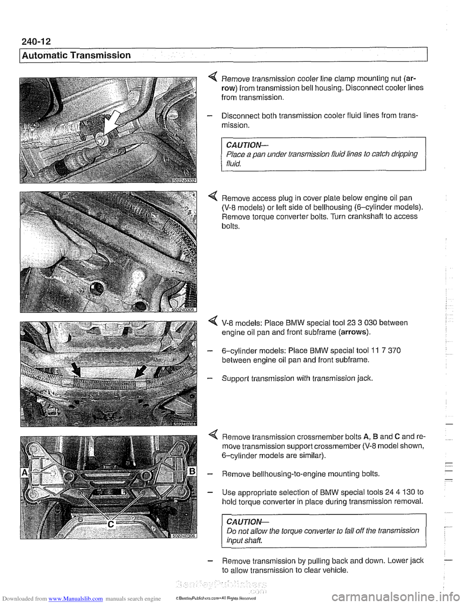
4 Remove transmission cooler line clamp mounting nut (ar-
row) from transmission bell housing. Disconnect cooler lines
from transmission.
- Disconnect both transmission cooler fluid lines from trans-
mission.
CAUTION-
Place a pan under transmission fluid lines to catch dripping
fluid.
4 Remove access plug in cover plate below engine oil pan
(V-8 models) or left side of bellhousing (6-cylinder models).
Remove torque converter bolts. Turn
cranltshaft to access
bolts.
V-8 models: Place BMW special tool 23 3 030 between
engine oil pan and front
subframe (arrows).
- 6-cylinder models: Place BMW special tool 11 7 370
between engine oil pan and front subframe.
- Support transmission with transmission jack.
4 Remove transmission crossmember bolts A, B and C and re-
move transmission support crossmember
(V-8 model shown,
6-cylinder models are similar).
- Remove bellhousing-to-engine mounting bolts.
- Use appropriate selection of BMW special tools 24 4 130 to
hold torque converter in place during transmission removal.
CAUTION-
Do not allow the torque converter to fall off the transmission
input shaft
- Remove transmlsslon by pull~ng back and down. Lower jack
to allow transmiss~on to clear vehicle.
rrs corn-hi8 Rniiti Riranrd
Page 598 of 1002

Downloaded from www.Manualslib.com manuals search engine
. .
l~utomatic Transmission
Tightening torques
ATF drain plug to ATF pan
A4S 310R 25 Nm (I8 ft-lb)
A5S 360R I A5S
390R (M14) 18 Nm (14 ft-lb)
A5S 3252 35 Nm (26 ft-lb)
A5S 5602 50 Nm (37 ft-lb)
A5S 4402 (M
16) 30 Nm (23 ft-lb)
ATF fill plug
to transmission housing
A4S 310R 33 Nm (24 ft-lb)
A5S 360R I A5S 390R (M14) 18 Nm (14 ft-lb)
A5S
3252 30 Nm (23 ft-lb)
A5S 5602 100 Nm (74 ft-lb)
A5S
4402 (M18) 35 Nm (26 ft-lb)
Flex-disc to transmission output flange
MI0 (8.8 grade) 48 Nm (35 it-lb)
MI 0 (1 0.9 grade) 60 Nm (44 R-lb)
MI2 (8.8 grade) 81 Nm (60 ft-lb)
MI 2 (1 0.9 grade) 100 Nm (74 ft-lb)
MI4 140 Nm (103 it-lb)
Torque converter to drive plate 45 Nm (33 ft-lb)
(flywheel)
(MIO)
Transmission crossmember to chassis or transmission
M8 21 Nm (15 ft-lb)
MI0 42 Nm (32 it-lb)
Transmission cooler lines to transmission
Banjo bolt
(M18. A5S 4402 transmission)
Banio bolt
(M16)
25 Nm (18 ft-lb)
37 Nm (27 ft-lb) . . Banjo bolt cap screw
(M18, A5S 4402 transmission) 20 Nm (15 it-lb
Compression fitting
(MI4 or M16) 37 Nm (27 ft-lb)
Oil cooler
bracket to transmission
(M8) 21 Nm (15 ft-lb)
Transmission to engine
21 Nm (15 ft-lb)
42 Nm (31 ft-lb)
72 Nm (53 ft-lb)
Page 657 of 1002

Downloaded from www.Manualslib.com manuals search engine
31 0-21
Front Suspension
4 Remove four bearing hub mounting bolts (arrows) and tap
hub assembly out of steering knuckle.
4 Before installing new wheel bearing and hub assembly, be
sure hub and steering knuckle sealing surfaces are free of
dirt and grease.
- Installation is reverse of removal.
Replace hub mounting bolts.
Use new self-locking nuts at steering tie rod and stabilizer
link.
Tightening
torques
Road wheel lugs to hub 120i-10 Nm (89i-7ft-lb)
Stabilizer link to stabilizer bar
Steering tie rod to steering
ltnuckle
Tension strut to steering
knucltie
Wheel bearing hub to steering
Itnucltle (replace bolts)
65 Nm (48 ft-lb)
65
Nm (48 it-lb)
80 Nm (59 ft-lb)
1
lo Nm (81 ft-lb)
Page 692 of 1002

Downloaded from www.Manualslib.com manuals search engine
320-34
I Steerins and Wheel Alignment
Front toe and toe difference angle
Toe is the difference in the distance between the front of the
front wheels and the rear of the front wheels. It is adjusted by
altering the length of the tie rods.
Toe difference angle determines the progressively different
paths taken by the front wheels as the car is turning. In
V-8
models, it is set by the pitman arm adjustment, but depends
on accurate setting of the toe.
Toe adjustments should only be made on specialized align-
ment equipment and only with the car in normal loaded posi-
tion, described below.
- Set front wheel toe at tie rod ends:
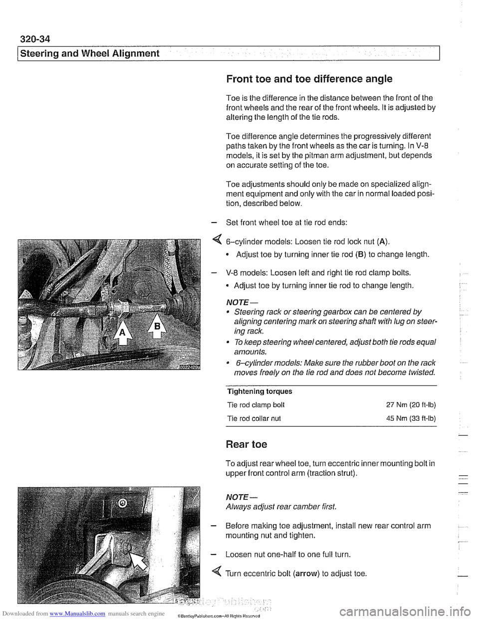
4 6-cylinder models: Loosen tie rod lock nut (A).
Adjust toe by turning inner tie rod (B) to change length
- V-8 models: Loosen left and right tie rod clamp bolts.
Adjust toe by turning inner tie rod to change length.
NOTE-
* Steering rack or steering gearbox can be centered by
aligning centering mark on steering shaft
with lug on steer-
ing rack.
To keep steering wheel centered, adjust both tie rods equal
amounts.
&cylinder models: Make sure the rubber boot on the rack
moves freely on the tie rod and does not become twisted.
Tightening torques
Tie rod clamp bolt
Tie rod collar
nut
27 Nm (20 ft-lb)
45 Nm (33 A-lb)
Rear toe
To adjust rear wheel toe, turn eccentric inner mounting bolt in
upper front control arm (traction strut).
NOTE-
Always adjust rear camber first.
- Before making toe adjustment, install new
mounting nut and tighten.
- Loosen nut one-half to one full turn.
4 Turn eccentric bolt (arrow) to adjust toe. rear
control arm