Page 617 of 1002

Downloaded from www.Manualslib.com manuals search engine
Driveshaft
- Road test vehicle to check for noise or vibration
CAUTION-
Do not reuse self-locking nuts. These nuts are designed to
be used only once.
Avoid stressing the flex-disc when torquing the bolts.
Do this by counterholding the bolts and turning the nuts
on the flange side.
Tightening torques
Alunlinum driveshaft to flex-disc
- MI2 (use coated washers)
90 Nm (66 ft-lb)
Driveshaft
CV joint to final drive flange
Mi0 (Tom bolt)
70 Nm (51 ft-lb)
M8 (compression nut) 32 Nm (24 ft-lb)
Flex-disc to transmission flange or driveshaft
MI0 (8.8 grade) 48 Nm (35 ft-lb)
MI 0 (1 0.9 grade) 60 Nm (44 ft-lb)
- Mi2 (8.8 grade)
81 Nm (60 ft-lb)
- MI2 (10.9 grade) I00 Nm (74 ft-lb)
MI4 140 Nm (103 ft-lb)
Transmission
crossmember
to transmission (ME) 21 Nm (15 ft-lb)
. to chassis (M10) 42 Nm (30 ft-lb)
NOTE-
Boltgrade is marked on the bolt head. When replacing bolts,
only use bolts of the same strength and hardness as the orig-
inals installed.
Flex-disc, replacing
- Checlc flex-disc between front section of driveshafl and trans-
mission output flange for craclts, tears, missing pieces, or
distortion. Check for worn bolt hole bores in flange.
- If flex-disc needs replacement, remove driveshafl as de-
scribed earlier.
- Unbolt flex-disc from driveshaft.
NOTE-
Removal andinstallation of the bolts may be made easier by
placing a large hose clamp around the flex-disc, and tighten-
ing the clamp slightly to compress the rubber.
Page 618 of 1002
Downloaded from www.Manualslib.com manuals search engine
260-1 2
1 Driveshaft
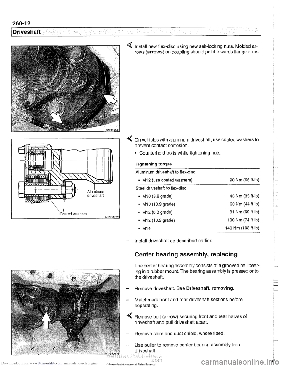
Install new flex-disc using new self-locking nuts. Molded ar-
rows (arrows) on coupling should point towards flange arms.
4 On vehicles with aluminum driveshaft, use coated washers to
prevent contact corrosion.
- Counterhold bolts while tightening nuts.
Tightening torque
Aluminum driveshaft to flex-disc
M12 (use coated washers) 90
Nm (66 ft-lb)
Steel driveshaft to flex-disc
MI0 (8.8 grade) 48
Nm (35 ft-lb)
- MI0 (10.9 grade) 60 Nm (44 ft-lb)
Coated washers - MI2 (8.8 grade) 5027500 . Mi2 (10.9 grade)
M14 81
Nm (60 ft-lb) 100 Nm (74 ft-lb)
140 Nm (103 ft-lb)
- Install driveshaft as described earlier
Center bearing assembly, replacing
The center bearing assembly consists of a grooved ball bear-
ing in a rubber mount. The bearing assembly is pressed
the driveshaft.
- Remove driveshaft. See Driveshaft, removing
- Matchmark front and rear driveshaft sections before
separating.
Remove bolt (arrow) securing front and rear halves of
driveshaft and pull driveshaft apart.
- Remove shim and dust shield, where fitted
- Use puller to remove center bearing assembly from
driveshaft. onto
Page 620 of 1002

Downloaded from www.Manualslib.com manuals search engine
260-14
Driveshaft
Constant velocity (CV) joint, replacing
The CV joint at the rear of the driveshaft is available from
BMW as a separate part.
- Remove complete driveshaft as described earlier in this
section.
< Clean grease off CV joint. Remove retaining circlip (arrow)
from CV joint end of driveshaft.
- Drive out bolts from CV joint.
4 Remove CV joint from driveshaft:
Pry back protective boot
(A).
- Using BMW special tool 26 1 110 on inner race (B), press
or pull joint off shaft.
- Check protective boot for damage. Replace if necessary.
- lnstall new CV joint:
. Working from both sides of joint, inject approximately 80
grams of
OptimolB grease (or equivalent) into joint.
Install new sealing gasket on joint face that mates with pro-
tective boot. Seal fits in groove on outer race of joint.
Clean grease off driveshaft and mating splines on joint.
Apply
LoctiteO 648 to driveshaft splines.
Press new CV joint onto shaft as far as it will go.
CAUTIOI\C
Only press on inner CVjoint race.
- Install new retaining circlip to end of driveshaft,
- Insert CV joint mounting bolts. Be sure to reuse washers.
- Install driveshaft as described earlier in this section.
Page 622 of 1002

Downloaded from www.Manualslib.com manuals search engine
[~us~ension, Steering and Brakes - General
This section of the manual covers front and rear suspension,
braking and steering systems, and contains wheel, tire and
wheel alignment information and specifications. Also covered
here are the integrated braking and suspension systems in-
cluding
antilock braking (ABS), traction control (ASCIDSC),
and electronic height control (EHC).
Vehicle ride height information is at the end of this repair
group. Alignment information is in
320 Steering and Wheel
Alignment.
Aluminum suspension components
In order to reduce vehicle weight, aluminum suspension com-
ponents are used in some models. A test with a magnet will
easily reveal the metal used. If working with aluminum com-
ponents, be sure to read and follow the cautions below.
CAUTION-
* Due to the chemical and corrosion characteristics of alumi-
num, do not bring into contact with battery acid.
Do not use wire brushes with brass or iron bristles.
Only use brushes with stainless steel bristles.
Do not expose to flying sparks from
grinding/cutting op-
erations.
Do not subject to steel welding splashes.
Do not expose to temperatures over
80°C (176"F),
even for short periods. Temperatures in painting facili-
ties are not a problem.
The E39 front suspension subframe is used as a rigid mount-
ing platform for the front suspension arms, stabilizer bar and
steering gear.
The suspension arms, known as the lower control arms and
the tension struts (thrust arms), are connected to the
sub-
frame through rubber bushings. The arms are connected to
the steering
knucltles in a double pivot configuration.
Each front strut assembly includes a tubular strut and a coil
spring. The upper strut mount includes a bearing. The lower
end of each strut housing is fitted to the steering knuckle. The
integral wheel bearing and hub are bolted to the steering
Iknucltle.
6-cylinder and V-8 models use different steering systems and
other front suspension components.
Page 701 of 1002

Downloaded from www.Manualslib.com manuals search engine
330-5
Rear Suspension
REAR STRUTS AND SPRINGS
(SEDAN MODELS)
Rear strut assembly, removing and
installing
Replace struts and coil springs in pairs only.
- Raise car and remove rear wheels.
WARNING -
Male sure the car is firmly supported on jack stands de-
signed for the purpose. Place jack stands underneath struc-
tural chassis points. Do not place jack stands under
suspension parts.
- Remove rear parcel shelf:
Remove rear seat headrests by pulling straight up.
Remove both rear roof pillar (C-pillar) trim panels.
Unbolt rear seat
belt anchors. See 720 Seat Belts.
Models with fixed rear seat: Remove rear seat backrest.
See 520 Seats.
* Models with fold-down rear seat: Remove rear seat back-
rest side sections. See 520 Seats. Fold down backrest.
* Working inside trunk, remove roller blind mounting nuts
and bolts, if applicable. Also disconnect roller blind har-
ness connector at right edge of rear seat backrest.
Gently pry rear speaker cover grilles and rear window defog-
ger grilles
(A) out of parcel shelf.
Carefully remove seat belt and headrest mount finisher
strips (B).
Remove
middle seat headrest anchor bolts (C). Remove
headrest anchor.
Remove expansion rivets (arrows) and lift out parcel shelf.
- Remove rear speakers.
- Remove rear wheels. Remove wheel arch trim
- Support rear wheel bearing carrier.
CAUTION-
The strutassembly prevents the drive axle and wheel bearing
carrier
from dropping too far. Supporting the wheel bearing
carrierbefore disconnecting the strut mounting fasteners pre-
vents damage to the brake hose, parking brake cable and
drive axle
CV joints.
Page 796 of 1002
Downloaded from www.Manualslib.com manuals search engine
400-2
Body-General
This chapter covers system descriptions and general infor-
mation for the repair groups found in sections
4 Body and
5 Body Equipment.
Body dimensions (in inches)
E39 sedan E39
Sport Wagon
Page 833 of 1002

Downloaded from www.Manualslib.com manuals search engine
Trunk Lid, ~ail~atel
Loosen bolts at lefl and right trunk
to point where lid can be moved. hinges
fasteners (arrows)
4 Remove plastic cover from lower trunlc lock. Loosen lock
bolts (arrows) until lock assembly can be moved.
CAUTION-
Before locking trunklid, check that trunk lid is not able to dam-
age the body or rear window.
4 Carefully close trunk lid and check side gaps (arrows). Min-
imum gap is 0.5 mm (0.02 in).
Adjust to fit side body panels.
Open trunlc lid.
Be careful not to alter adjustments.
Tighten lower trunlc lock fasteners.
Close trunk lid and check adjustments.
Repeat process if necessary.
- Close trunk lid. Measure gap between trunlc lid and lower
body panel.
Position lower section of rear trunlc lid
lock higher or lower
so that a
ciao of 5.0 mm (0.04 in) exists between trunlc lid
and
lowe;body panel. '
Check adjustment and repeat if necessary,
4 Screw out detent buffers (arrow) until left and right sides of
trunk lid rest against detent buffers with lid closed.
Page 842 of 1002
Downloaded from www.Manualslib.com manuals search engine
41 2-1 4
l~runk Lid, Tailgate
< Loosen left and right lateral guide to body fasteners (arrows)
until guide can be moved.
4 Loosen left and right tailgate lateral guide fasteners (arrow)
and fully retract guides.
Check fulcrum pads (arrows) on lower section of tailgate
lock for damage. Replace if necessary.

