1998 BMW 528i Section 6
[x] Cancel search: Section 6Page 232 of 1002

Downloaded from www.Manualslib.com manuals search engine
1 16-56
Cylinder Head and Valvetrain
This section covers valve removal and reconditioning, includ-
ing valve guides, seats, springs, and valve stem oil seals.
Valves, leak test
To test the valves for leakage, the cylinder head must be dis-
assembled with camshafts and camshaft carriers removed.
With valve assemblies and spark plugs installed, place the
cylinder head on a workbench with the combustion chamber
facing upward. Fill each combustion chamber with a thin non-
flammable liquid. After fifteen minutes,
check the level of the
fluid. If the fluid level in any cylinder drops, that cylinder is not
sealing properly.
Valves, removing and installing
- Remove cylinder head as described in 113 Cylinder Head
Removal and Installation.
CAUTIOI\C
(M52 TU/M54 engines only) Do not let the hydraulic lifters
fall out as the camshaft carrier is removed. Special suction
cups are available from
BMW to hold the hydraulic lifters in
place during carrier removal.
* Hydraulic cam lifters should be stored m an uprfght po-
sition. If necessary, use a magnetic tool to
aidin remov-
al of the lifters.
- Remove valves using a valve spring compressor.
CAUTIOI\C
Label each valve assembly as it is removed so it can be in-
stalled in its original position.
-
- Remove and discard valve stem oil seals from valve guides.
See Valve stem oil seals later in this section.
- Valve installation is reverse of removal. Remove carbon de- - -
posits from the valves using a wire brush or wire wheel. -
-
Valve specifications are listed in Table c. Valve specifica-
tions.
Page 319 of 1002

Downloaded from www.Manualslib.com manuals search engine
Camshaft Timing chain/
- Tighten accessible sprocket retaining bolts in the following
order:
Leit exhaust camshaft
Right exhaust
camshait
Leit intake camshaft
Right
intalte camshait
Tightening torque
Sprocket bolts to camshaft flange
15 Nm (1 1 ft-lb)
- Remove BMW special tool 11 2 300 from tool bore at bell-
housing and remove
camshaft loclting tools from cylinder
heads.
Using crankshaft center bolt, turn engine over clockwise at
least one
comolete rotation so that remainino camshaft
sprocltet
retaking bolts are accessible. -
- Tighten remaining camshait sprocket retaining bolts
Tightening torque Sprocket bolts to camshaft
flange 15 Nm (I 1 It-lb)
- Remove BMW special tool 11 3 390 from primary timing
chain tensioner bore and reinstall primary chain tensioner
- Remainder of installation is reverse or removal, noting the fol-
lowing:
Remove gasket residue from cylinder head sealing sur-
face.
Apply a thin bead of Three Bond 1209
O sealing com-
pound to joints at cylinder head cover and timing case cov-
er and at half-moon sections at rear of cylinder heads.
Replace cylinder head cover
gaskets if necessary.
Page 338 of 1002

Downloaded from www.Manualslib.com manuals search engine
119-18
I Lubrication System
4 Working at lefl side of engine, remove oil dipstick guide tube 1 mounting bracket and remove dipstick tube.
NOTE-
Replace dipstick O-ring seal.
< Working at right side of engine, remove oil return line from
upper section of oil pan.
4 Separate lower steering column from steering box:
Remove retaining bolt
(arrow) from lower steering column
universal joint.
Slide lower steering column up and off of connection at
steering box.
- Remove support bracket for hydraulic line at subframe.
Page 340 of 1002
Downloaded from www.Manualslib.com manuals search engine
Lubr~cat~on System r- -
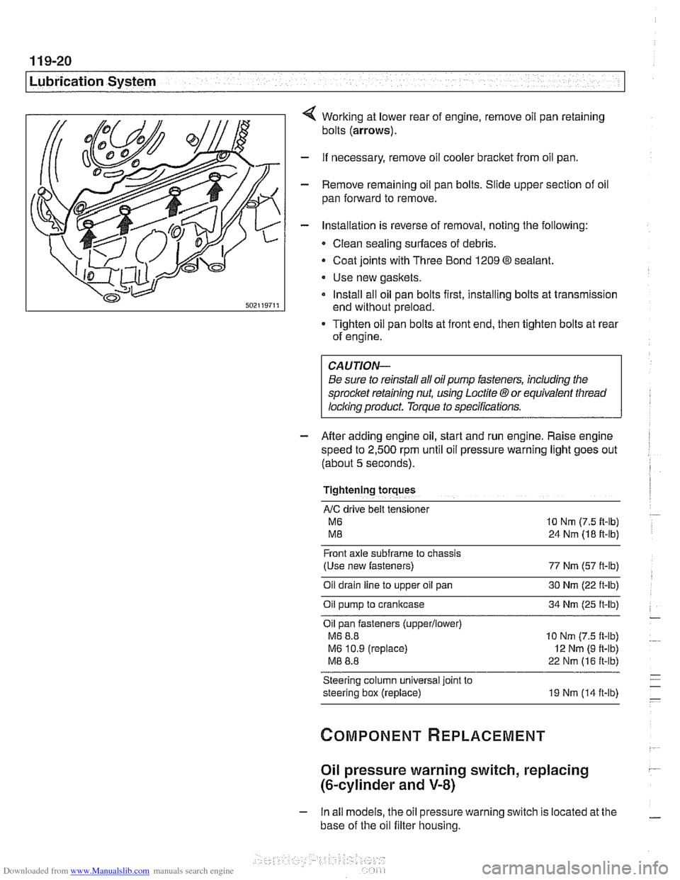
Working at lower rear of engine, remove oil pan retaining
bolts
(arrows).
- If necessary, remove oil cooler bracket from oil pan.
- Remove remaining oil pan bolts. Slide upper section of oil
pan forward to remove.
- Installation is reverse of removal, noting the following:
Clean sealing surfaces of debris.
- Coat joints with Three Bond 1209 O sealant.
Use new gaskets.
Install all oil pan bolts first, installing bolts at transmission
end without preload.
Tighten oil pan bolts at front end, then tighten bolts at rear
of engine.
Be sure to reinstall all oil
pump fasteners, including the
sprocl
speed to
2,500 rpm until oil pressure warning light goes out
(about
5 seconds).
Tightening torques
AIC drive belt tensloner
M6 10 Nm (7.5 it-lb)
M8 24 Nm (18 ft-lb)
Front axle
subframe to chassis
(Use new fasteners) 77 Nm (57 ft-lb)
Oil drain
line to upper oil pan 30 Nm (22 ft-lb)
Oil pump to crankcase 34 Nm (25 ft-lb)
Oil pan fasteners
(upperllower)
M6 8.8 10 Nm (7.5 ft-lb)
M6 10.9 (replace)
I2 Nm (9 ft-lb)
M8 8.8 22 Nm (16 ft-lb)
Steering column universal joint to
steering box (replace) 19 Nm (14 ft-lb)
Oil pressure warning switch, replacing
(&cylinder and V-8)
- In all models, the oil pressure warning switch is located at the
base of the oil filter housing.
Page 368 of 1002

Downloaded from www.Manualslib.com manuals search engine
- -
Battery, Starter, Alternator
This section covers the battery, alternator, starter and associ-
ated components of the electrical system.
Troubleshooting information
forthese components isfound in
Table a. Battery, alternator and starter troubleshooting.
For additional electrical troubleshooting information, see
600 Electrical System-General.
Special tools
4 Automotive digital multimeter
CAUTION-
Only use a digital multirneter when testing automotive electri- I) cal components.
4 Closed-circuit current measurement adaptor
(Tool No.
BMW 61 2 300)
Engine electrical system
The alternator and starter are wired directly to the battery. To
prevent accidental shorts that might blow a fuse or damage
wires and electrical components, always disconnect the
negative
(-) battery cable before working on the electrical
system.
Various versions of alternators, voltage regulators, starters,
and batteries are used in
E39 cars. Replace components ac-
cording to the original equipment specification.
Page 396 of 1002

Downloaded from www.Manualslib.com manuals search engine
130-6
Fuel Injection
Fuel supply to the injection system is provided by a high pres-
sure electric pump mounted inside the fuel tank. The pump is
powered via the fuel pump relay. If the relay is faulty, the fuel
pump will not run and the engine will not start.
NOTE-
* Fuel delivery volume and fuel pressure are critical to prop-
er operation. Fuel pressure direcfly influences fuel deliv-
ery
Fuel pump relay, fuel pressure and fuel volume tests are
given in 160 Fuel Tank and Fuel Pump.
Relieving system fuel pressure
The fuel system retains fuel pressure in the system when the
engine is off. To prevent fuel from spraying on a hot engine,
system fuel pressure should be relieved beforedisconnecting
fuel lines. One method is to tightly wrap
ashop towel around a
fuel line fitting and loosen or disconnect the fitting. Cleanli-
ness is essential when working with fuel components. Thor-
oughly clean the unions before disconnecting fuel lines.
When system faults are detected, a diagnostic trouble code
(DTC) is stored in the engine control module (ECM). The MIL
also iiluminates if an emissions-related fault is detected
When faults arise, or if the malfunction indicator lamp (MIL) is
illuminated, begin troubleshooting by connecting BMW ser-
vice tester
DISplus. MoDiC, GTI or equivalent scan tool. The
capabilities of OBD
II software has the potential to save hours
of diagnostic time and to help avoid incorrect component re-
placement and possible damage to system components.
CAUTION-
- The tests in this section may set fault codes (DTCs) in the
ECM and illuminate the
MIL. Affer all testing is completed,
access and clear DJC fault memory using an
OED I1 or
BMW compatible scan tool. See OBD On-Board Diag-
nostics.
0 Only use a digital multimeter for electrical tests.
. Relay positions can vary Be sure to confirm relay posi-
tion by identifying the wiring in the socket using the wir-
ing diagrams found in ELE Electrical Wiring
Diagrams.
Page 413 of 1002

Downloaded from www.Manualslib.com manuals search engine
- -.
Fuel Injection
SIEMENS MIS 42.0 AND 43.0
When system faults are detected, a diagnostic trouble code
(DTC) is stored in the engine control module (ECM). The MIL
also illuminates
if an emissions-related fault is detected.
When faults arise, or
if the malfunction indicator lamp (MIL) is
illuminated, begin troubleshooting by connecting BMW ser-
vice tester
DISplus, MoDiC, GTI or equivalent scan tool. The
capabilities of OBD
II software has the potential to save hours
of diagnostic time and to help avoid incorrect component re-
placement and possible damage to system components.
CAUTION-
* The tests in this section may set fault codes (DTCs) in tlie
ECM and illuminate the MIL. After all testing is completed,
access and clear DTC fault
memory using an OBD I/ or
BMW compatible scan tool. See
OBD On-Board Diag-
nostics.
Only use a
dgital multimeter for electrical tests.
Relay positions can vary. Be sure to confirm
relayposi-
tion by identifying the wiring in the socket using the wir-
ing diagrams found in
ELE Electrical Wiring
Diagrams.
NOTE-
- OBD I1 fault memory. (including an illuminated MIL! can
only be reset using the special scan tool. Removing the
connector from the ECM or disconnecting the battery will
not erase the fault memory.
The BMW-dedicated 20-pin diagnostic
linlc connector
(DLC) is in the right rear of the engine compartment The
20-pin DLC is discontinued on models after
6/2000.
The 1 &pin OBD I1 diagnostic connector (arrow) is located
inside the car on the lower left dash panel.
The MS
42.0 and MS 43.0 systems manage the following
functions.
- Air:
Idle speed valve
Electronic throttle
Hot film mass air flow (MAF) sensor
Resonance-turbulence intake control
- Fuel:
* Fuel supply
Running losseslnon return
Fuel injection
Page 436 of 1002
Downloaded from www.Manualslib.com manuals search engine
130-46
Fuel Injection
When system faults are detected, a diagnostic trouble code
(DTC) is stored in the engine control module (ECM). The MIL
also illuminates if an emissions-related fault is detected.
When faults arise, or
if the malfunction indicator lamp (MIL) is
illuminated, begin troubleshooting by connecting BMW ser-
vice tester
DISplus. MoDiC, GTI or equivalent scan tool. The
capabilities of
OED II software has the potential to save hours
of diagnostic time and to help avoid incorrect component re-
placement and possible damage to system components.
CA UTIOiU-
The tests in this section may set fault codes (DTCs) in the
ECM and illuminate the MIL. After ail testing is completed,
access and clear DTC fault
memory using an OED I/ or
BMW compatible scan tool. See OBD On-Board Diag-
nostics.
Only use a digital
multimeter for electrical tests.
Relay positions can vary. Be sure to confirm relay
posi-
. tion by identifying the wiring in the socket using the wir-
ing diagrams-found in ~~~~lectrical Wiring
Diagrams.
NOTE-
OED I1 fault memory (including an illuminated MIL) can
only be reset
using~the special scan tool. Removing the
connector from the ECM or disconnecting the battery will
not erase the fault
memory.
The BMW-dedicated 20-pin diagnostic link connector
(DLC) is in the right rear of the engine compartment.
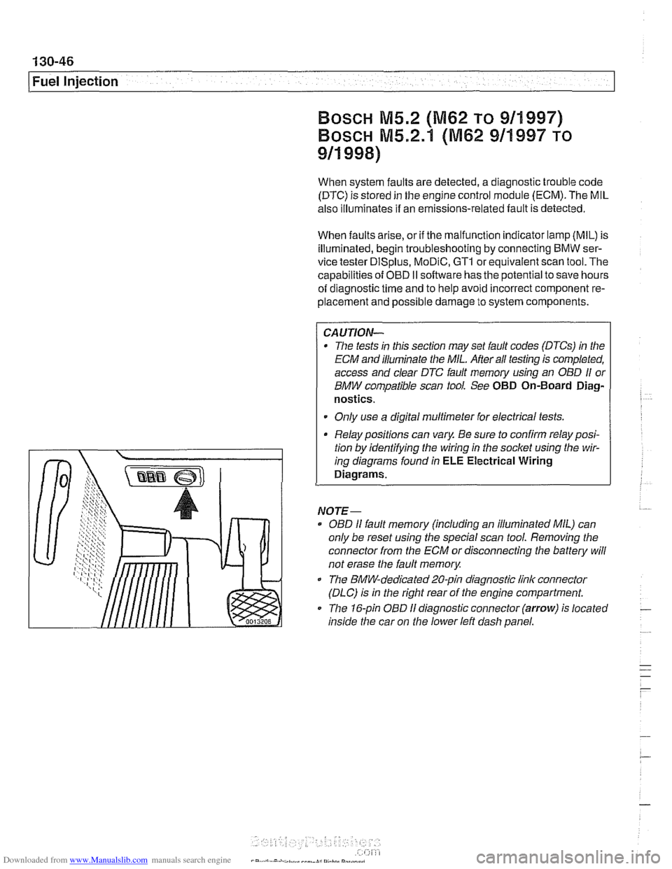
The 16-pin OBD
I1 diagnostic connector (arrow) is located
inside the car on
the lower left dash panel.