1998 AUDI S4 turn
[x] Cancel search: turnPage 9 of 72
9
SSP 198/03
Cooling circuit
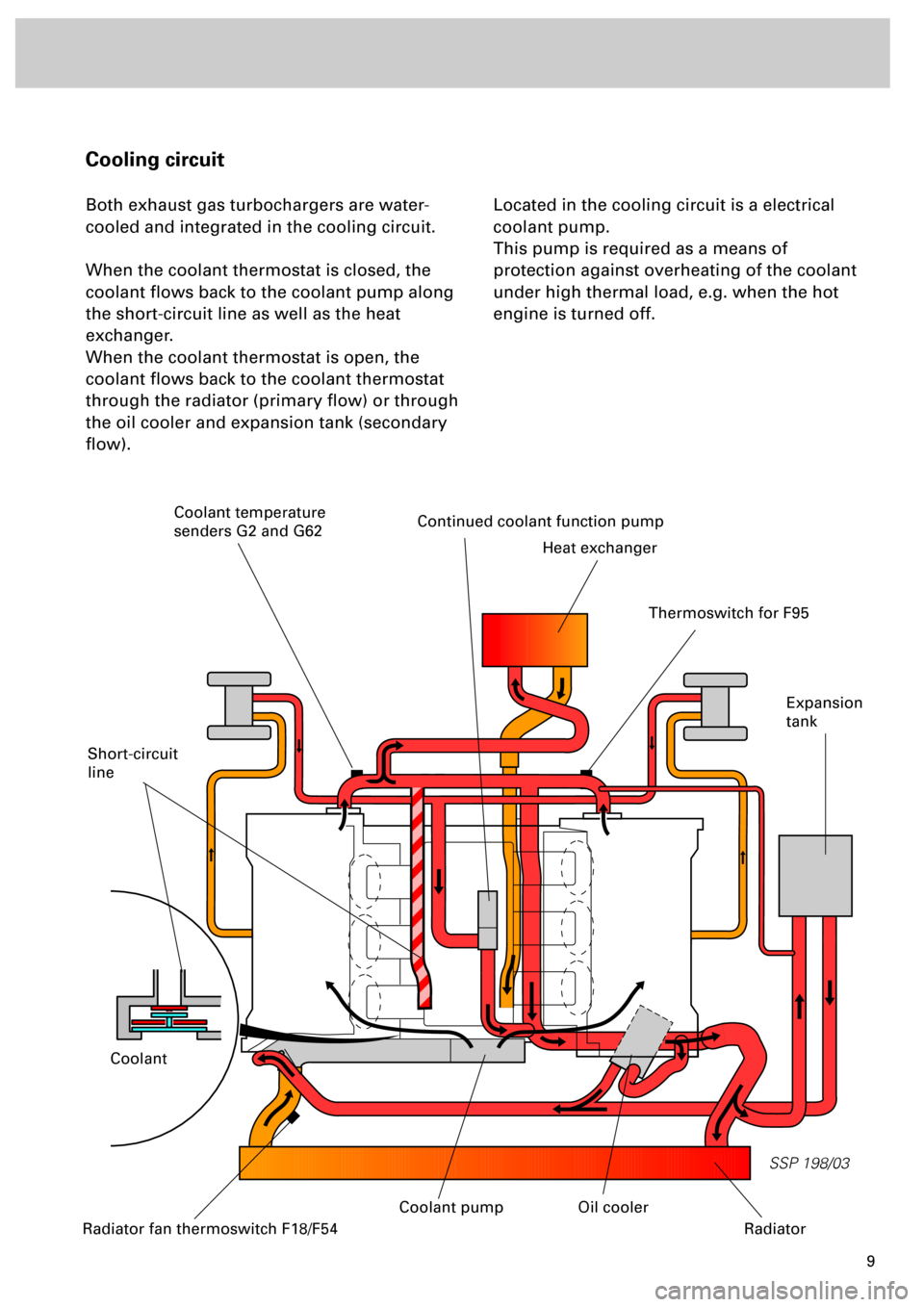
Both exhaust gas turbochargers are water-
cooled and integrated in the cooling circuit.
When the coolant thermostat is closed, the
coolant flows back to the coolant pump along
the short-circuit line as well as the heat
exchanger.
When the coolant thermostat is open, the
coolant flows back to the coolant thermostat
through the radiator (primary flow) or through
the oil cooler and expansion tank (secondary
flow).Located in the cooling circuit is a electrical
coolant pump.
This pump is required as a means of
protection against overheating of the coolant
under high thermal load, e.g. when the hot
engine is turned off.
Short-circuit
line
Continued coolant function pump
Heat exchanger
Coolant
Expansion
tank
Radiator fan thermoswitch F18/F54
Oil cooler
Radiator
Thermoswitch for F95
Coolant temperature
senders G2 and G62
Coolant pump
Page 14 of 72
1415
SSP 198/49
Engine
Engine lubrication
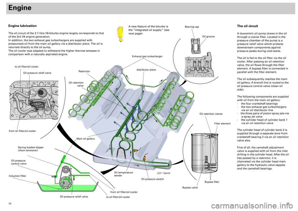
The oil circuit of the 2.7-litre V6 biturbo engine largely corresponds to that
of the 3rd V6 engine generation.
In addition, the two exhaust gas turbochargers are supplied with
pressurised oil from the main oil gallery via a distributor piece. The oil is
returned directly to the oil sump.
The oil cooler was adapted to withstand the higher thermal stresses in
comparison with a naturally aspirated engine.A new feature of the biturbo is
the “integrated oil supply“ (see
next page).
to oil filter/oil cooler
Spring-loaded slipper
(chain tensioner)
Main oil gallery
Oil retention valves
Bypass valve
Filter element
Bearing cap
Oil groove
Oil temperature
sender
Oil pressure switch
Restrictor
Oil retention
valve
distributor piece
The oil circuit
A duocentric oil pump draws in the oil
through a coarse filter. Located in the
pressure chamber of the pump is a
pressure relief valve which protects
downstream components against
pressure peaks during cold starts.
The oil is fed to the oil filter via the oil
cooler. After passing an oil retention
valve, the oil flows through the filter
element. A bypass filter is connected in
parallel with the filter element.
The oil subsequently reaches the main
oil gallery. A branch line is routed to the
oil pressure control valve (clean oil
side).
The following components are supplied
with oil from the main oil gallery:
- the four crankshaft bearings
- the two exhaust gas turbochargers
via an oil distributor line
- the three pairs of piston spray jets via
a spray jet valve
- the cylinder head of cylinder bank 1
via an oil retention valve
The cylinder head of cylinder bank 2 is
supplied through a separate bore from
crankshaft bearing 2 via an oil retention
valve also.
First of all, the camshaft adjustment
valve is supplied with oil from the inlet
drilling in the cylinder head. After the oil
has passed by a restrictor, it is
channeled via the cylinder head main
gallery to the hydraulic valve tappets
and the camshaft bearings.
Exhaust gas turbocharger
Bypass filter
Oil pressure relief valve
from oil filter/oil coolerOil pressure
control valveInduction filter
Oil pressure relief valve
from oil filter/oil cooler
to oil filter/oil cooler
Page 16 of 72
17
is a pressure relief valve. It is located inside the
oil pump housing and opens when the oil
pressure rises too high (cold start). If an
excessively high oil pressure builds up,
various component parts of the oil circuit (e.g.
oil filter, oil cooler) may be damaged. Also,
there is the possibility of the inlet and exhaust
valves opening or no longer closing, due to
“bulking“ of the hydraulic tappets. The knock-
on effect of this is that the engine can no
longer be started or cuts out.
The oil pressure limiting valve ......
regulates the engine oil pressure. It is
integrated in the oil pump housing. The oil
quantity “regulated“ by the oil pressure
control valve is fed to the suction side of the
oil pump.
This helps to optimise efficiency.
The oil pressure control valve ......
prevent the oil running out of the oil filter and
the cylinder heads and back into the oil sump
while the engine is stationary.
The oil retention valves ......
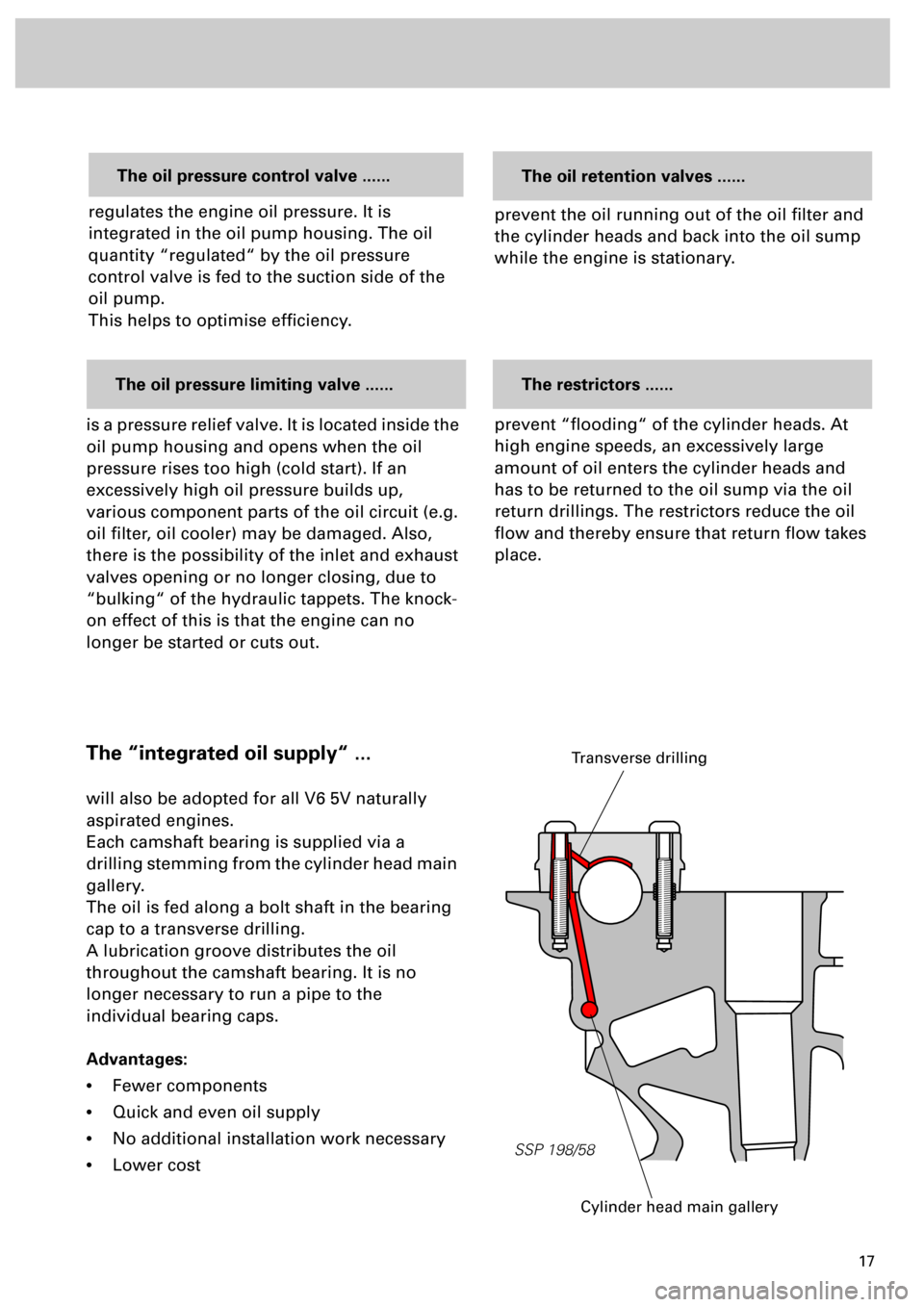
The “integrated oil supply“ ...
will also be adopted for all V6 5V naturally
aspirated engines.
Each camshaft bearing is supplied via a
drilling stemming from the cylinder head main
gallery.
The oil is fed along a bolt shaft in the bearing
cap to a transverse drilling.
A lubrication groove distributes the oil
throughout the camshaft bearing. It is no
longer necessary to run a pipe to the
individual bearing caps.
Advantages:
•
Fewer components
•
Quick and even oil supply
•
No additional installation work necessary
•
Lower cost
SSP 198/58
Cylinder head main gallery
Transverse drilling
prevent “flooding“ of the cylinder heads. At
high engine speeds, an excessively large
amount of oil enters the cylinder heads and
has to be returned to the oil sump via the oil
return drillings. The restrictors reduce the oil
flow and thereby ensure that return flow takes
place.
The restrictors ......
Page 24 of 72
25
SSP 198/31
Pneumatically controlled systems
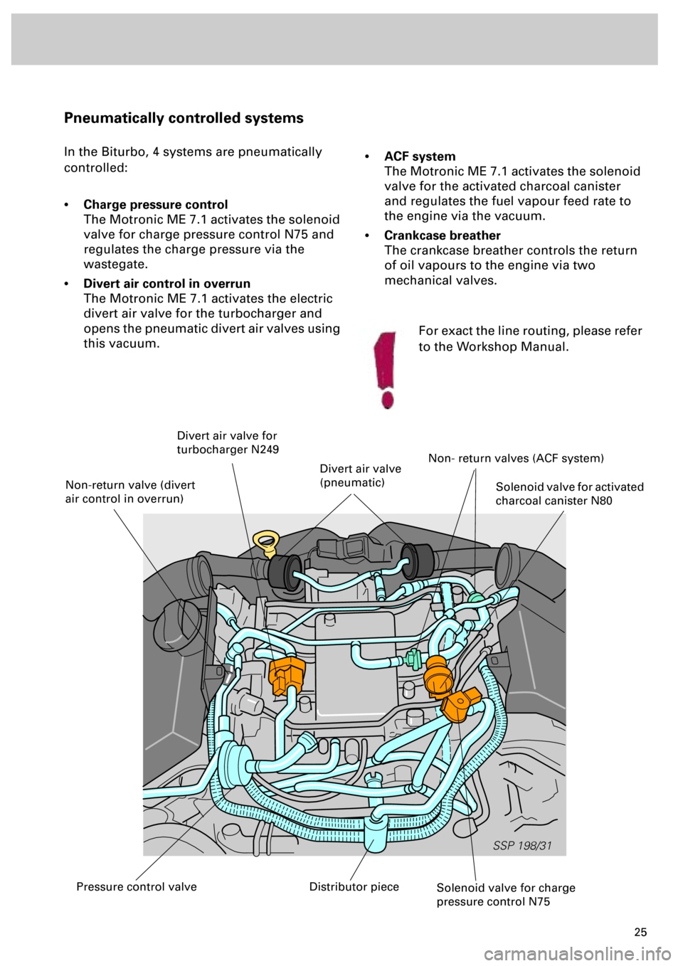
In the Biturbo, 4 systems are pneumatically
controlled:
•
Charge pressure control
The Motronic ME 7.1 activates the solenoid
valve for charge pressure control N75 and
regulates the charge pressure via the
wastegate.
•
Divert air control in overrun
The Motronic ME 7.1 activates the electric
divert air valve for the turbocharger and
opens the pneumatic divert air valves using
this vacuum.
•
ACF system
The Motronic ME 7.1 activates the solenoid
valve for the activated charcoal canister
and regulates the fuel vapour feed rate to
the engine via the vacuum.
•
Crankcase breather
The crankcase breather controls the return
of oil vapours to the engine via two
mechanical valves.
Solenoid valve for charge
pressure control N75
Solenoid valve for activated
charcoal canister N80
Divert air valve for
turbocharger N249
Non- return valves (ACF system)
Distributor piecePressure control valve
Non-return valve (divert
air control in overrun)
Divert air valve
(pneumatic)
For exact the line routing, please refer
to the Workshop Manual.
Page 27 of 72
28
SSP 198/05
Engine
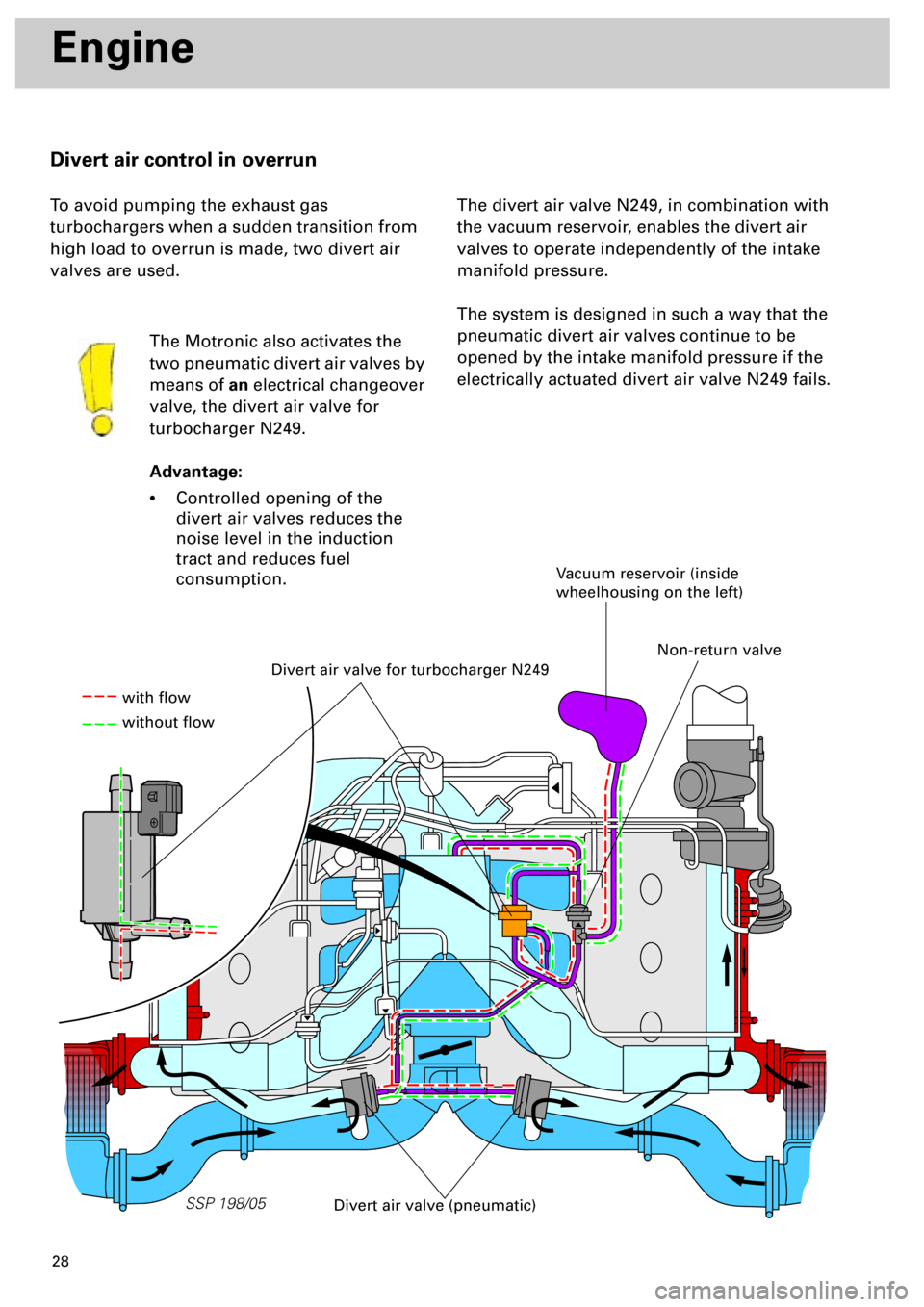
Divert air control in overrun
To avoid pumping the exhaust gas
turbochargers when a sudden transition from
high load to overrun is made, two divert air
valves are used.
The Motronic also activates the
two pneumatic divert air valves by
means of
an
electrical changeover
valve, the divert air valve for
turbocharger N249.
Advantage:
•
Controlled opening of the
divert air valves reduces the
noise level in the induction
tract and reduces fuel
consumption.
The divert air valve N249, in combination with
the vacuum reservoir, enables the divert air
valves to operate independently of the intake
manifold pressure.
The system is designed in such a way that the
pneumatic divert air valves continue to be
opened by the intake manifold pressure if the
electrically actuated divert air valve N249 fails.
Divert air valve for turbocharger N249
Vacuum reservoir (inside
wheelhousing on the left)
Divert air valve (pneumatic)
with flow
without flow
Non-return valve
Page 28 of 72
29
SSP 198/06
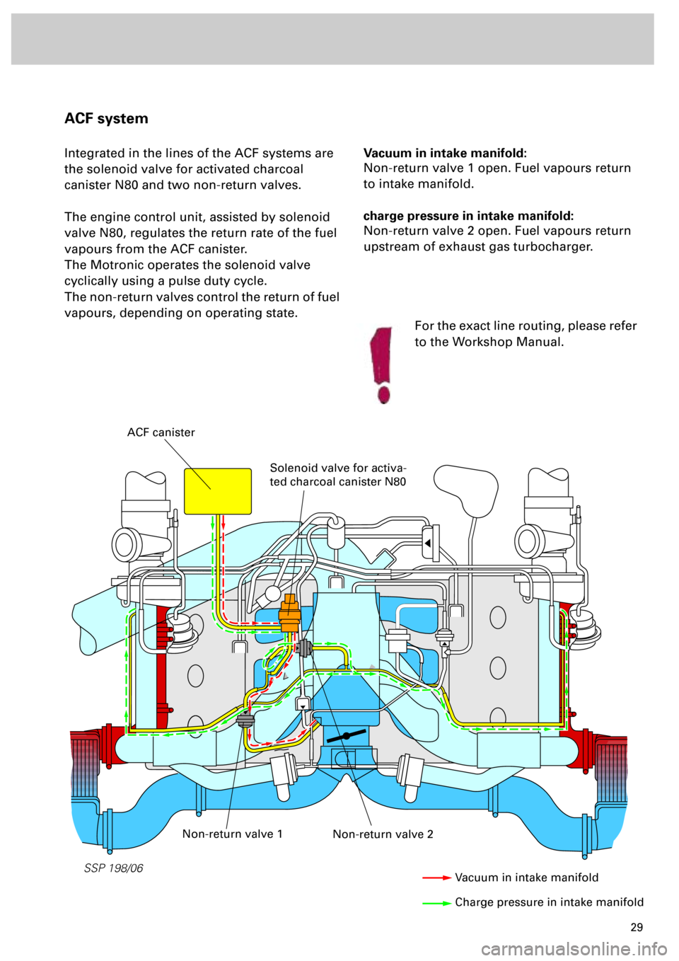
Vacuum in intake manifold:
Non-return valve 1 open. Fuel vapours return
to intake manifold.
charge pressure in intake manifold:
Non-return valve 2 open. Fuel vapours return
upstream of exhaust gas turbocharger.
ACF system
Integrated in the lines of the ACF systems are
the solenoid valve for activated charcoal
canister N80 and two non-return valves.
The engine control unit, assisted by solenoid
valve N80, regulates the return rate of the fuel
vapours from the ACF canister.
The Motronic operates the solenoid valve
cyclically using a pulse duty cycle.
The non-return valves control the return of fuel
vapours, depending on operating state.
ACF canister
Solenoid valve for activa-
ted charcoal canister N80
Non-return valve 2Non-return valve 1
Vacuum in intake manifold
Charge pressure in intake manifold
For the exact line routing, please refer
to the Workshop Manual.
Page 29 of 72
30
SSP 198/07
Engine
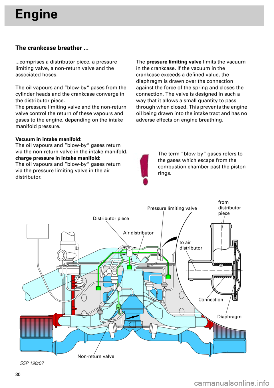
The crankcase breather ...
...comprises a distributor piece, a pressure
limiting valve, a non-return valve and the
associated hoses.
The oil vapours and “blow-by“ gases from the
cylinder heads and the crankcase converge in
the distributor piece.
The pressure limiting valve and the non-return
valve control the return of these vapours and
gases to the engine, depending on the intake
manifold pressure.
Vacuum in intake manifold:
The oil vapours and “blow-by“ gases return
via the non-return valve in the intake manifold.
charge pressure in intake manifold:
The oil vapours and “blow-by“ gases return
via the pressure limiting valve in the air
distributor.The pressure limiting valve limits the vacuum
in the crankcase. If the vacuum in the
crankcase exceeds a defined value, the
diaphragm is drawn over the connection
against the force of the spring and closes the
connection. The valve is designed in such a
way that it allows a small quantity to pass
through when closed. This prevents the engine
oil being drawn into the intake tract and has no
adverse effects on engine breathing.
Distributor piece
Pressure limiting valve
Non-return valve
The term “blow-by“ gases refers to
the gases which escape from the
combustion chamber past the piston
rings.
Connection
Diaphragm
Air distributor
to air
distributor
from
distributor
piece
Page 43 of 72
44
Subsystems of the Motronic
120
180
°C 60
90
12
93
6
120
°C 60
12
16
120
100
80
50
30
10140
1234
5
6
7
160
180
200
220
260
Volt8
1/2
1/1
8
0
EPC
EPC
SSP 198/47
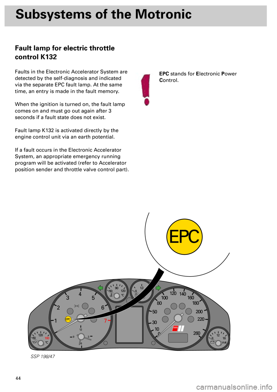
Fault lamp for electric throttle
control K132
Faults in the Electronic Accelerator System are
detected by the self-diagnosis and indicated
via the separate EPC fault lamp. At the same
time, an entry is made in the fault memory.
When the ignition is turned on, the fault lamp
comes on and must go out again after 3
seconds if a fault state does not exist.
Fault lamp K132 is activated directly by the
engine control unit via an earth potential.
If a fault occurs in the Electronic Accelerator
System, an appropriate emergency running
program will be activated (refer to Accelerator
position sender and throttle valve control part).
EPC
stands for
E
lectronic
P
ower
C
ontrol.