Page 2 of 72
2
The 2.7-litre V6 biturbo .......
Turbocharged engines are already something
of a tradition at AUDI. The task now facing
AUDI’s engineers was to develop a worthy
successor to the 5-cylinder turbocharged
engine.
One of the key development goals for the
turbocharged engine was to achieve a good
level of dynamic response, particularly at the
bottom end of the rev band.
........ a further milestone in engine development by Audi!
The goal of AUDI’s engineers was to realise a
high “basic torque level“ and a torque
characteristic that rises in direct proportion to
engine speed to its peak.
The term “basic torque level“
describes the torque which is
immediately available when the
throttle is opened (e.g. at part
throttle or in overrun).
SSP 198/77
Page 3 of 72

3
This Self-study Programme provides you with information
regarding design and function.
The Self-study Programme is not a Workshop Manual!
Please refer to the Service Literature for all the relevant
maintenance and repair instructions.
Page
Engine .........................................................
Technical data, crankshaft, cylinder head,
camshaft timing, cooling circuit, engine
lubrication, overview of components, air ducting,
charging, exhaust system, pneumatically
controlled systems, charge pressure control, air
divert control in overrun, ACF system, crankcase
breather
4
Motronic ME 7.1 ..........................................
Subfunctions, system overview
31
Subsystems of the Motronic .....................
Torque-oriented engine management, torque-
oriented functional structure, Electronic throttle,
exhaust gas temperature control
33
Sensors .......................................................
Additional sensors of the Motronic
49
Auxiliary signals/interfaces ...................... 57
Functional diagram ..................................... 62
Self-diagnosis .............................................
Vehicle diagnosis, test and information system
VAS 5051, test box V.A.G 1598/31
64
Transmission ..............................................
Self-adjusting clutch, gearbox
66
Contents
Important!/Note!
New!
Page 4 of 72
4
Engine
The 2.7-litre V6 biturbo
This engine will also be used in the Audi S4
and Audi A6.
The engine used in the A6 has a comfort-
oriented setup, which means that it has
different torque and power output.
This effect was principally achieved by
modifying the software configuration of the
engine control unit.A tuning protective device prevents
the S4 engine control unit being
installed in the A6!
This prevents misuse, which can
result in damage to the drivetrain!
An auxiliary heater is not available
as an option for the S4 and the A6,
due to the constraints on space.
BITURBO
SSP 198/01
Page 5 of 72

5
The technical data
•
Configuration:
V6 engine with 90° V-angle and twin
turbochargers
•
Engine code:
S4: AGB
A6: AJK
•
Output:
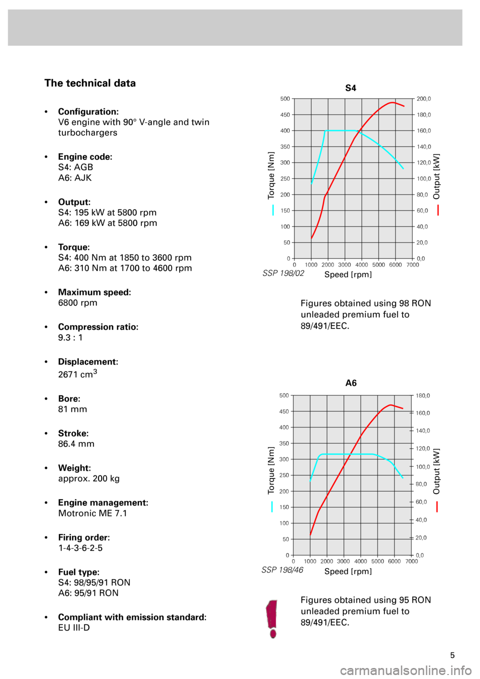
S4: 195 kW at 5800 rpm
A6: 169 kW at 5800 rpm
•
Torque:
S4: 400 Nm at 1850 to 3600 rpm
A6: 310 Nm at 1700 to 4600 rpm
•
Maximum speed:
6800 rpm
•
Compression ratio:
9.3 : 1
•
Displacement:
2671 cm
3
•
Bore:
81 mm
•
Stroke:
86.4 mm
•
Weight:
approx. 200 kg
•
Engine management:
Motronic ME 7.1
•
Firing order:
1-4-3-6-2-5
•
Fuel type:
S4: 98/95/91 RON
A6: 95/91 RON
•
Compliant with emission standard:
EU III-DFigures obtained using 98 RON
unleaded premium fuel to
89/491/EEC.
Figures obtained using 95 RON
unleaded premium fuel to
89/491/EEC.
500
450
400
350
300
250
200
150
100
50
0200,0
180,0
160,0
140,0
120,0
100,0
80,0
60,0
40,0
20,0
0,0
0 1000 2000 3000 4000 5000 6000 7000
SSP 198/02
Speed [rpm]
Torque [Nm]Output [kW]
S4
500
450
400
350
300
250
200
150
100
50
0180,0
160,0
140,0
120,0
100,0
80,0
60,0
40,0
20,0
0,0
0 1000 2000 3000 4000 5000 6000 7000
SSP 198/46
Speed [rpm]
Torque [Nm]Output [kW]
A6
Page 7 of 72
7
Cylinder head
The cylinder heads are largely identical to
those used in the V6 naturally aspirated
engine. Common parts are used for both banks
of cylinders.
The mounting position of the right-hand
cylinder head is rotated through an angle of
180° in relation to the left-hand cylinder head.
The timing of the inlet camshafts is engine-
dependent.
To improve heat dissipation, the exhaust
valves are sodium-filled.The shape of the inlet duct causes the drawn-
in air to tumble.
Advantages:
•
A good degree of swirl and high ignitability
fuel-air mixture are achieved
•
The tumble effect allows more efficient
combustion
For a turbocharged engine, the compression
ratio of 9.3 : 1 is high.
Advantage:
•
High ”basic torque level“ and fuel
economy
Tumble duct
In combination with five-valve-
per-cylinder technology, the inlet
duct is shaped as a so-called
“tumble duct“.
Tumble duct
Tumble effect
SSP 198/78
Page 8 of 72

8
Engine
The variable valve timing
The camshaft timing has been modified
compared to the 2.8-litre V6 engine to meet the
demands of turbocharging technology.
Variable valve timing with an adjustment angle
of 22° is used here for the first time in
turbocharged engines
.
Advantage:
•
A torque increase of approx. 10% is
achieved at the bottom and top ends of the
engine speed range.
•
Better emission levels and fuel
consumption figures.
The variable valve timing is activated by the
Motronic by means of camshaft adjustment
valves N205 and N208.The design and function of the
variable valve timing are already
described in Self-study Programmes
182 and 192.
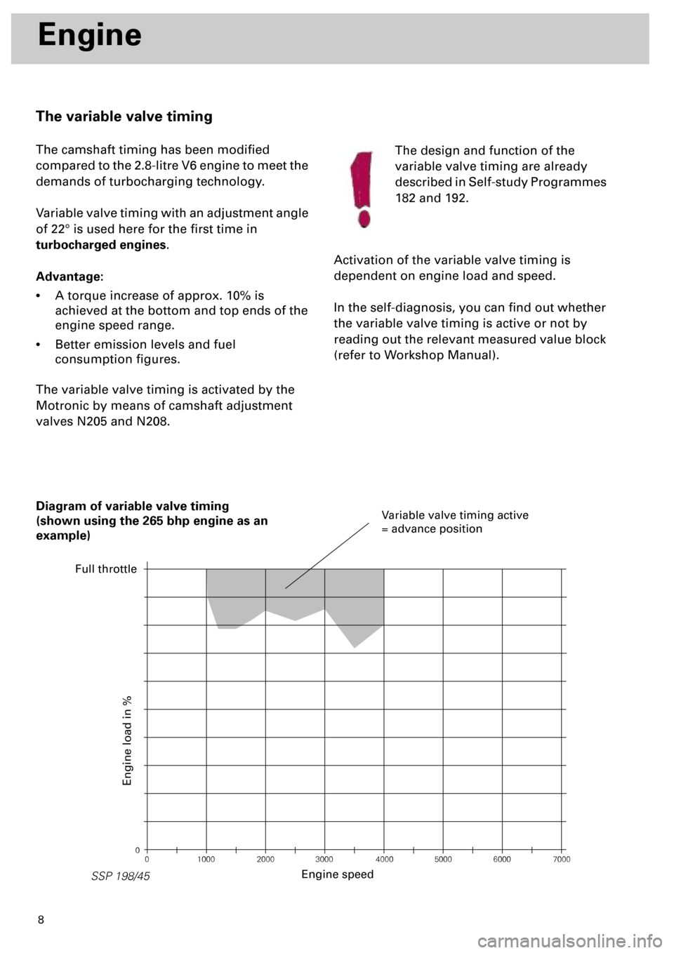
Activation of the variable valve timing is
dependent on engine load and speed.
In the self-diagnosis, you can find out whether
the variable valve timing is active or not by
reading out the relevant measured value block
(refer to Workshop Manual).
0
0 1000 2000 3000 4000 5000 6000 7000
SSP 198/45
Diagram of variable valve timing
(shown using the 265 bhp engine as an
example)
Engine speed
Engine load in %
Variable valve timing active
= advance position
Full throttle
Page 25 of 72

26
SSP 198/08
Engine
Charge pressure control
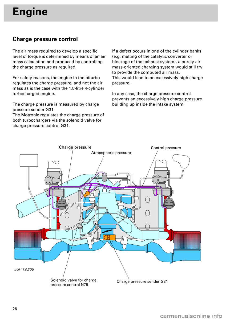
The air mass required to develop a specific
level of torque is determined by means of an air
mass calculation and produced by controlling
the charge pressure as required.
For safety reasons, the engine in the biturbo
regulates the charge pressure, and not the air
mass as is the case with the 1.8-litre 4-cylinder
turbocharged engine.
The charge pressure is measured by charge
pressure sender G31.
The Motronic regulates the charge pressure of
both turbochargers via the solenoid valve for
charge pressure control G31.
If a defect occurs in one of the cylinder banks
(e.g. melting of the catalytic converter or
blockage of the exhaust system), a purely air
mass-oriented charging system would still try
to provide the computed air mass.
This would lead to an excessively high charge
pressure.
In any case, the charge pressure control
prevents an excessively high charge pressure
building up inside the intake system.
Charge pressure sender G31
Atmospheric pressure
Solenoid valve for charge
pressure control N75
Charge pressure
Control pressure
Page 30 of 72
31
Motronic ME 7.1
Subfunctions of the Motronic
The Motronic consists of known and new subfunctions:
Sequential injection
Charge pressure control
(see chapter on “Engine” pp. 26 and 27)
Stereo lambda control
Mapped ignition
Cylinder-selective knock control
Static high-tension distribution with 6 individual ignition coils
ACF system
Torque-oriented engine management
Electrically actuated throttle valve (Electronic accelerator)
Cylinder bank-specific exhaust gas temperature control
Mapped variable valve timing (intake camshaft adjustment)
(see chapter on “Engine” p. 8)
New
New
New
New
l
SSP 198/44