Page 33 of 72
34
Subsystems of the Motronic
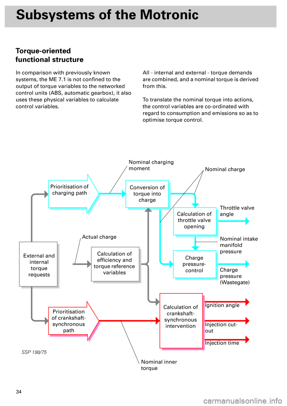
In comparison with previously known
systems, the ME 7.1 is not confined to the
output of torque variables to the networked
control units (ABS, automatic gearbox), it also
uses these physical variables to calculate
control variables.All - internal and external - torque demands
are combined, and a nominal torque is derived
from this.
To translate the nominal torque into actions,
the control variables are co-ordinated with
regard to consumption and emissions so as to
optimise torque control.
SSP 198/75
External and
internal
torque
requests
Calculation of
efficiency and
torque reference
variables
Prioritisation of
charging path
Prioritisation
of crankshaft-
synchronous
path
Conversion of
torque into
charge
Throttle valve
angle
Charge
pressure-
control
Calculation of
crankshaft-
synchronous
intervention
Calculation of
throttle valve
opening
Charge
pressure
(Wastegate)
Ignition angle
Injection cut-
out
Injection time
Nominal charging
moment
Nominal charge
Nominal intake
manifold
pressure
Nominal inner
torque
Actual charge
Torque-oriented
functional structure
Page 34 of 72
35
The control variable calculation is subdivided
into two paths
Path 1
The charging path regulates the control
variables which influence charging:
• Throttle valve angle
• Charge pressure
Path 2
All control actions which influence torque
regardless of charging are combined in the
crankshaft-synchronous path:
• Ignition angle
• Injection cut-out
• Injection time
The air mass necessary to develop a specific
torque is determined by means of a
“calculation model“ and is made available
along path
1
.
Path
2
is used to set the injection quantity or
cylinder cut-out necessary under the given
circumstances and the optimal ignition angle.
Prioritisation of
charging pathPrioritisation
of crankshaft-
synchronous
path
By and large, long-term torque requests are
fulfilled along path
1
.
Path 2
is particularly well suited to meeting
short-term torque requests, which usually
have a torque-reducing effect.
Page 35 of 72
36
SSP 198/09
Subsystems of the Motronic
Electrically actuated throttle
valve (electronic accelerator)
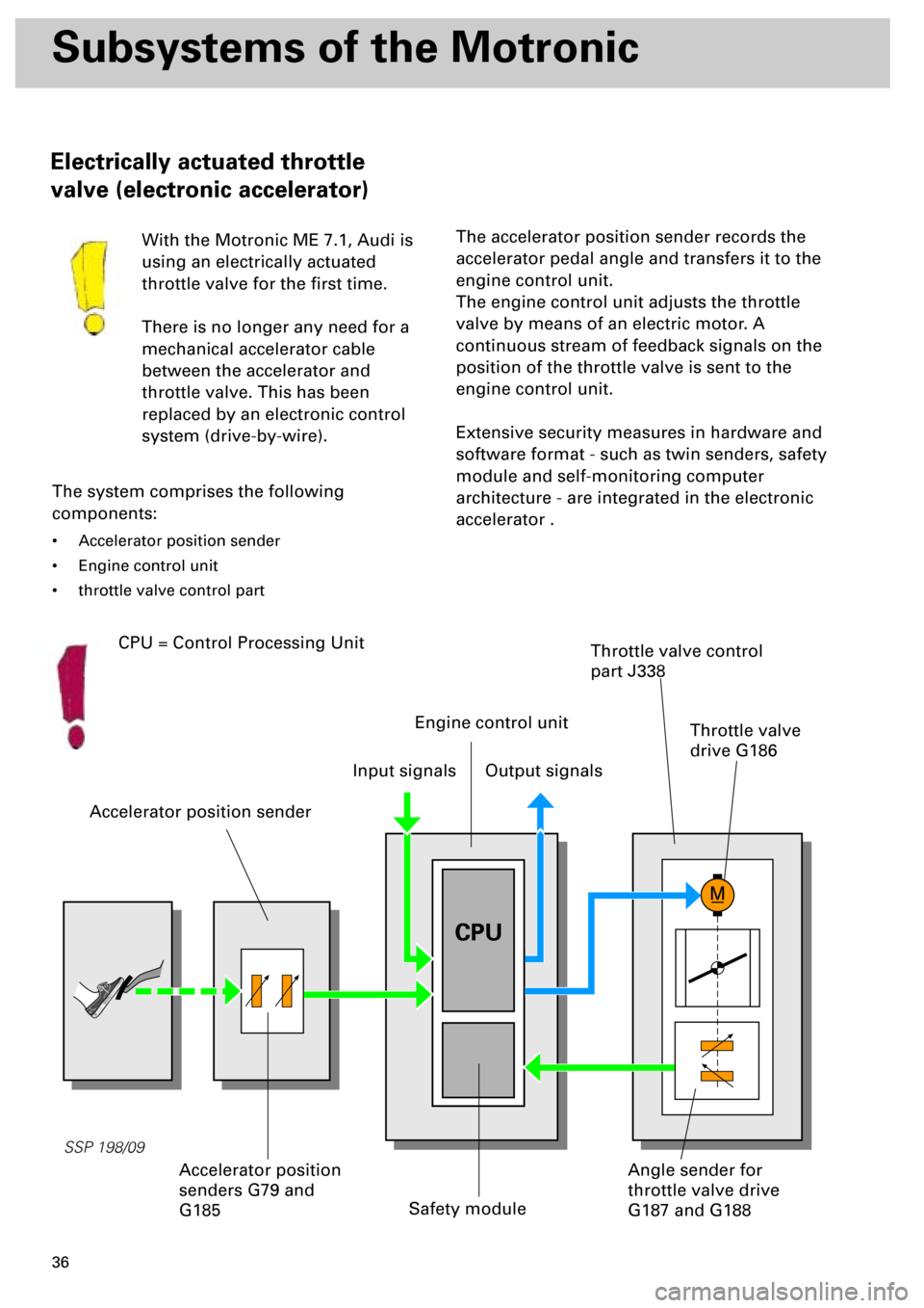
With the Motronic ME 7.1, Audi is
using an electrically actuated
throttle valve for the first time.
There is no longer any need for a
mechanical accelerator cable
between the accelerator and
throttle valve. This has been
replaced by an electronic control
system (drive-by-wire).
The system comprises the following
components:
• Accelerator position sender
• Engine control unit
• throttle valve control part
Accelerator position sender
Safety module
Throttle valve control
part J338
The accelerator position sender records the
accelerator pedal angle and transfers it to the
engine control unit.
The engine control unit adjusts the throttle
valve by means of an electric motor. A
continuous stream of feedback signals on the
position of the throttle valve is sent to the
engine control unit.
Extensive security measures in hardware and
software format - such as twin senders, safety
module and self-monitoring computer
architecture - are integrated in the electronic
accelerator .
Input signalsOutput signals
Angle sender for
throttle valve drive
G187 and G188Accelerator position
senders G79 and
G185
Engine control unit
CPU
CPU = Control Processing Unit
Throttle valve
drive G186
Page 36 of 72
37
The electronic accelerator controls the engine
output electronically and, over and above
intake-air control, offers the advantage that
functions such as idling speed control, cruise
control or engine governing can be executed
easily and comfortably.
.
The throttle valve can be opened regardless of
the accelerator position, and this serves to
reduce throttle losses.
The ideal combination of throttle valve cross-
section and charge pressure produce the
necessary torque.
In this way, the throttle valve can be opened
fully while the accelerator pedal has not been
fully depressed.With electronic accelerator, much improved
emissions and higher fuel economy are
achieved in specific load states.
Over and above this, any accelerator
characteristic can be programmed, e.g.
gradual acceleration when driving at low
speed.
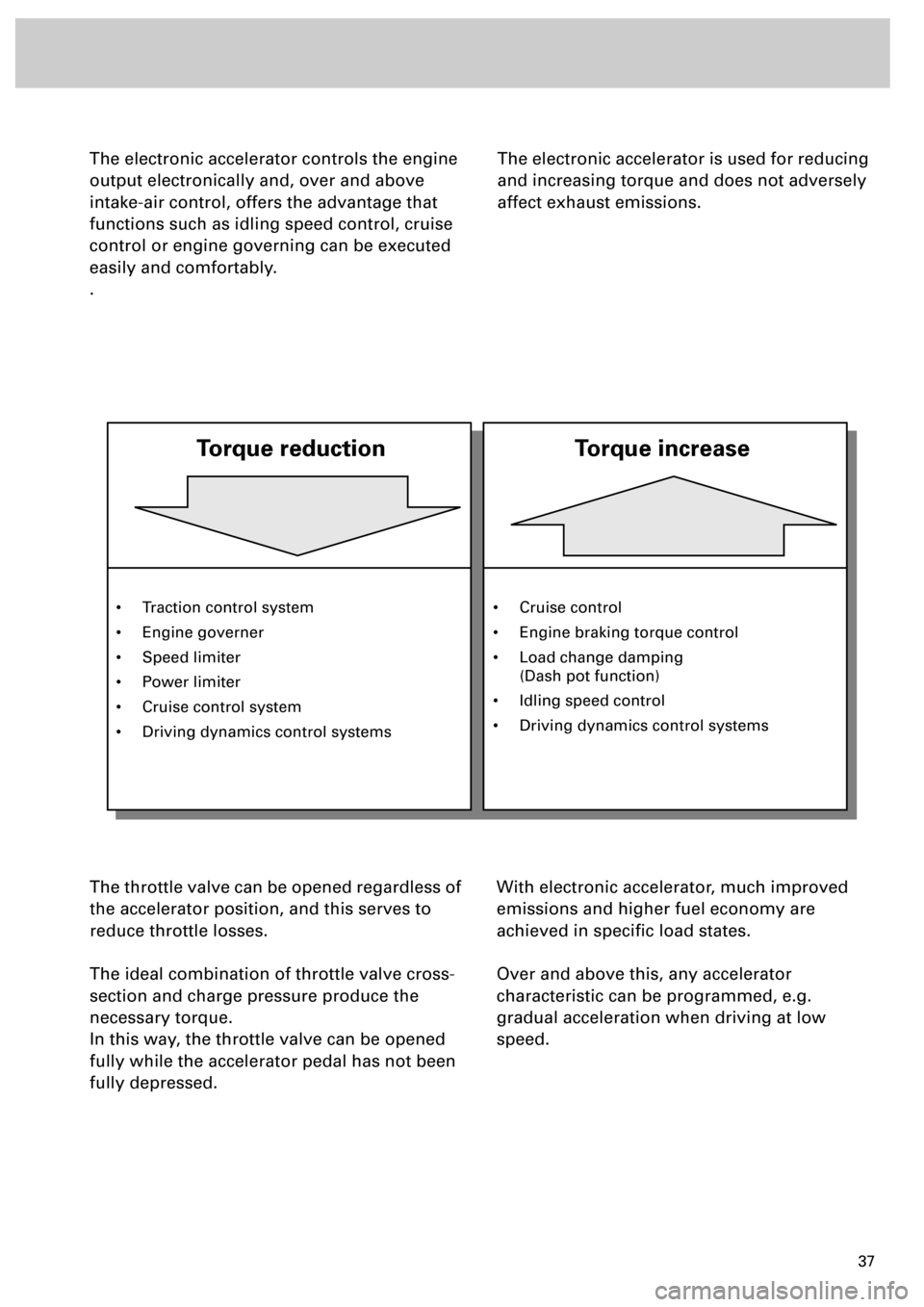
The electronic accelerator is used for reducing
and increasing torque and does not adversely
affect exhaust emissions.
• Traction control system
• Engine governer
• Speed limiter
• Power limiter
• Cruise control system
• Driving dynamics control systems
Torque reduction
Torque increase
• Cruise control
• Engine braking torque control
• Load change damping
(Dash pot function)
• Idling speed control
• Driving dynamics control systems
Page 38 of 72
39
Self-diagnosis/emergency
running
If a fault occurs in the accelerator position
sender or the wiring, two emergency running
programs can be run depending on fault type.
Emergency running program 1
If an accelerator position sender fails:
• Accelerator position limited to a defined value.
• If a full load is predefined, the power output is
increased slowly.
• In the case of implausible signals between G79
and G185, the lower value is used.
Prerequisite:
The idling speed position must be learnt once
by the intact sender.
• The signal supplied by brake light switch for
brake pedal switch F47 indicates the idling
speed.
• Comfort functions (CCS) are prohibited.
• The fault lamp for electric throttle control K132
comes on.
Emergency running program 2
If both accelerator position senders fail, driver
input recognition is not possible:
• The engine only runs at idling speed.
• The fault lamp for electric throttle control K132
comes on.
At idling speed, the accelerator
position senders G79 and G185 are
not diagnosed.
If the plug of the accelerator position
sender drops off, no fault is stored in
the control unit.
The fault lamp for electric throttle
control K132 does not come on.
The engine runs at idling speed and
does not respond to the accelerator
pedal.
Safety function:
For safety reasons, the throttle valve
is closed as far as a defined angular
position when both the accelerator
pedal and the brake pedal are
depressed.
If the brake is pressed first followed
by the accelerator pedal, the driver
input (torque request) is executed.
Page 39 of 72
40
SSP 198/28
Subsystems of the Motronic
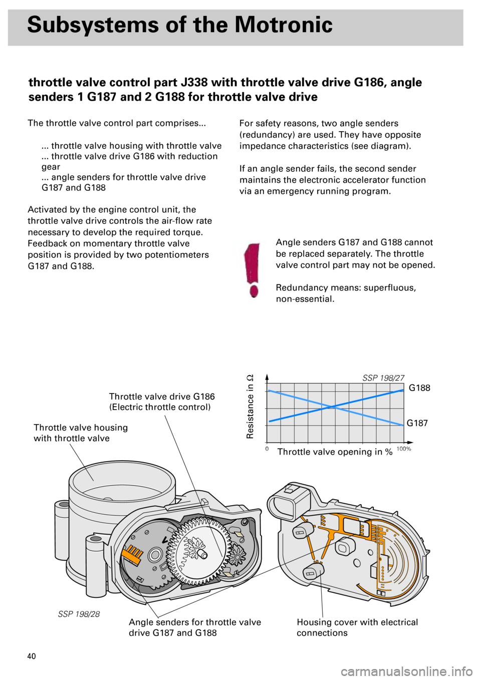
The throttle valve control part comprises...
... throttle valve housing with throttle valve
... throttle valve drive G186 with reduction
gear
... angle senders for throttle valve drive
G187 and G188
Activated by the engine control unit, the
throttle valve drive controls the air-flow rate
necessary to develop the required torque.
Feedback on momentary throttle valve
position is provided by two potentiometers
G187 and G188.
For safety reasons, two angle senders
(redundancy) are used. They have opposite
impedance characteristics (see diagram).
If an angle sender fails, the second sender
maintains the electronic accelerator function
via an emergency running program.
Throttle valve housing
with throttle valve
Housing cover with electrical
connections
Throttle valve drive G186
(Electric throttle control)
Angle senders for throttle valve
drive G187 and G188
Resistance in
W
Angle senders G187 and G188 cannot
be replaced separately. The throttle
valve control part may not be opened.
Redundancy means: superfluous,
non-essential.
0 100%
SSP 198/27
G188
G187
Throttle valve opening in %
throttle valve control part J338 with throttle valve drive G186, angle
senders 1 G187 and 2 G188 for throttle valve drive
Page 40 of 72
41
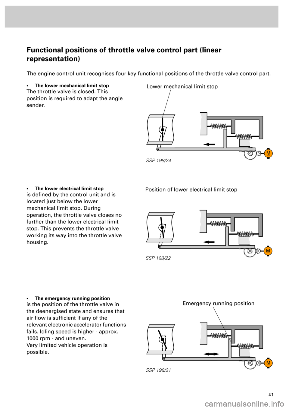
Functional positions of throttle valve control part (linear
representation)
The engine control unit recognises four key functional positions of the throttle valve control part.
• The lower mechanical limit stop
The throttle valve is closed. This
position is required to adapt the angle
sender.
• The lower electrical limit stop
is defined by the control unit and is
located just below the lower
mechanical limit stop. During
operation, the throttle valve closes no
further than the lower electrical limit
stop. This prevents the throttle valve
working its way into the throttle valve
housing.
• The emergency running position
is the position of the throttle valve in
the deenergised state and ensures that
air flow is sufficient if any of the
relevant electronic accelerator functions
fails. Idling speed is higher - approx.
1000 rpm - and uneven.
Very limited vehicle operation is
possible.
SSP 198/21
SSP 198/22
SSP 198/24
Position of lower electrical limit stop
Emergency running position
Lower mechanical limit stop
Page 41 of 72
42
Subsystems of the Motronic
To enable the exact angular position of the throttle valve to be identified, angle senders for
throttle valve drive G187 and G188 must be learnt .
By moving the throttle valve into predefined positions, the values of the angle senders are stored
in the control unit (calibrated) and checked for plausibility. The state of the mechanics (terminals,
weak springs) in the throttle valve control part is determined by evaluating the throttle valve’s
reaction speed.
... involves not only learning the throttle
valve position, but also a complete check of
the throttle valve control part
... can be performed using the following
three methods:
•
manually
- provided the ignition has been
switched on for at least 24 minutes without
operating the starter or accelerator.
•
automatically -
provided the need for adaption
is acknowledged.
•
specifically -
by initiating basic setting 04 in
measured value block 60 (refer to Workshop
Manual)
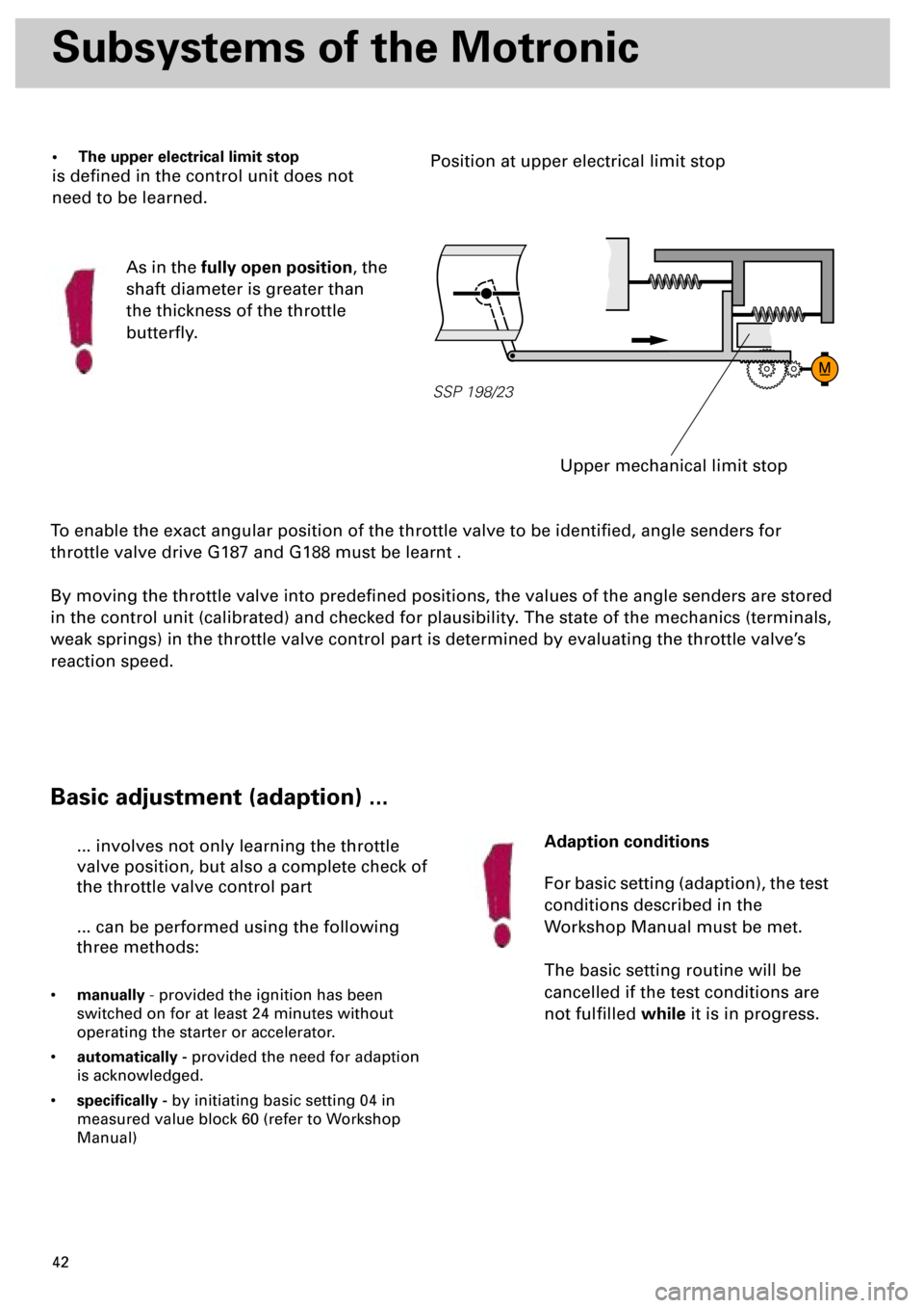
• The upper electrical limit stop
is defined in the control unit does not
need to be learned.
As in the
fully open position
, the
shaft diameter is greater than
the thickness of the throttle
butterfly.
SSP 198/23
Upper mechanical limit stop
Position at upper electrical limit stop
Basic adjustment (adaption) ...
Adaption conditions
For basic setting (adaption), the test
conditions described in the
Workshop Manual must be met.
The basic setting routine will be
cancelled if the test conditions are
not fulfilled
while
it is in progress.